MAZDA 6 2002 Workshop Manual Suplement
Manufacturer: MAZDA, Model Year: 2002, Model line: 6, Model: MAZDA 6 2002Pages: 909, PDF Size: 17.16 MB
Page 801 of 909

S–20
SLIDING SUNROOF
REAR DRAIN HOSE REMOVALA6E774069922201WGN
1. Remove the headliner.
2. Remove the trunk side upper trim and trunk side trim.
3. Disconnect the rear drain hose from the sunroof frame.
4. Remove the rear drain hose from the clips.
5. Pull the rear drain hose into the room side.
6. Remove the rear drain hose.
End Of Sie
SLIDING SUNROOF
A
AB
B
C
D
D C
A
A B
B
C E
ECRIGHT SIDE
LEFT SIDE
Sec. A—A
Sec. B
—B
Sec. C—C
Sec. E
—E Sec. D
—D
A6E77401101
Page 802 of 909

TRIM
S–21
S
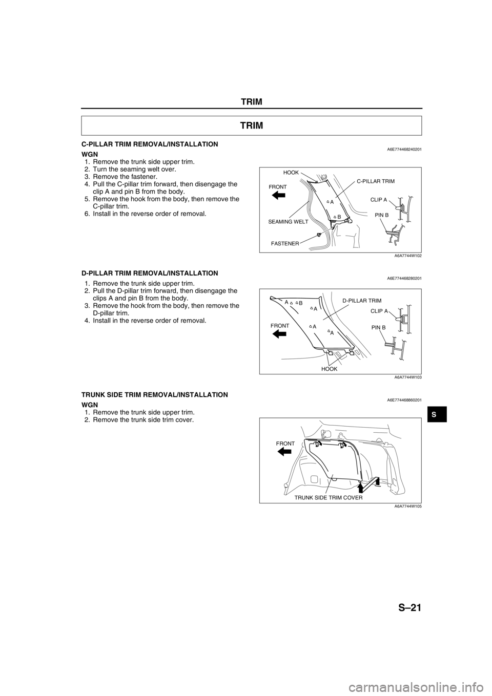
C-PILLAR TRIM REMOVAL/INSTALLATIONA6E774468240201WGN
1. Remove the trunk side upper trim.
2. Turn the seaming welt over.
3. Remove the fastener.
4. Pull the C-pillar trim forward, then disengage the
clip A and pin B from the body.
5. Remove the hook from the body, then remove the
C-pillar trim.
6. Install in the reverse order of removal.
End Of Sie
D-PILLAR TRIM REMOVAL/INSTALLATIONA6E7744682802011. Remove the trunk side upper trim.
2. Pull the D-pillar trim forward, then disengage the
clips A and pin B from the body.
3. Remove the hook from the body, then remove the
D-pillar trim.
4. Install in the reverse order of removal.
End Of Sie
TRUNK SIDE TRIM REMOVAL/INSTALLATIONA6E774468860201WGN
1. Remove the trunk side upper trim.
2. Remove the trunk side trim cover.
TRIM
A
BC-PILLAR TRIM
SEAMING WELTCLIP A
PIN B HOOK
FRONT
FASTENER
A6A7744W102
A B
AA AD-PILLAR TRIM
CLIP A
PIN B
HOOK FRONT
A6A7744W103
FRONT
TRUNK SIDE TRIM COVER
A6A7744W105
Page 803 of 909

S–22
TRIM
3. Remove the screw, then remove the bracket.
4. Remove the cargo hooks.
5. Remove the fasteners, then remove the trunk
side trim.
6. Install in the reverse order of removal.
End Of Sie
TRUNK SIDE UPPER TRIM REMOVAL/INSTALLATIONA6E774468860202WGN
1. Remove the tire house trim.
2. Remove the rear seat remote lever.
3. Remove the cargo hooks.
4. Remove the screw.
5. Pull the trunk side upper trim toward you, then
remove the hooks A, C, D and clips B, pin E from
the body.
6. Remove the trunk side upper trim.
7. Install in the reverse order of removal.
End Of Sie
FASTENER
TRUNK SIDE TRIM
CARGO HOOK FRONT
SCREW
BRACKET
A6E77441106
B AD C
A B
C
ED
SCREW TRUNK SIDE UPPER TRIM
CARGO HOOK FRONT
HOOK C
HOOK D HOOK A
PIN E CLIP B
A6A7744W107
Page 804 of 909

TRIM
S–23
S
TRUNK END TRIM REMOVAL/INSTALLATIONA6E774468890201WGN
1. Pull the trunk end trim upward, then disengage
clips A and pins B from the body.
2. Remove the trunk end trim.
3. Install in the reverse order of removal.
End Of Sie
LIFTGATE UPPER TRIM REMOVAL/INSTALLATIONA6E774468930201WGN
Without rear spoiler
Caution
•Removing the liftgate upper trim by pulling on the middle section of the trim could damage the
high-mount brake light. When removing the trim, be sure to pull on the side edges of the trim only.
1. Pull the liftgate upper trim on the side edges
towards you, then disengage pins A from the
body.
2. Pull the middle section of the trim towards you
and disengage clips B and pin C from the body.
3. Remove the liftgate upper trim.
4. Install in the reverse order of removal.
With rear spoiler
1. Pull the liftgate upper trim toward you, then
disengage the pin A, C and clip B from the body.
2. Remove the liftgate upper trim.
3. Install in the reverse order of removal.
End Of Sie
AB
A
A
B
A
A
A B
TRUNK END TRIM
PIN B
CLIP A
A6A7744W108
AC B
AB
CLIP B
PIN A LIFTGATE UPPER TRIM
PIN C
A6A7744W109
ABAB
C
CLIP BPIN C LIFTGATE UPPER TRIM
PIN A
A6A7744W110
Page 805 of 909

S–24
TRIM
LIFTGATE SIDE TRIM REMOVAL/INSTALLATIONA6E774468940201WGN
1. Remove the liftgate upper trim. (SeeS–23 LIFTGATE UPPER TRIM REMOVAL/INSTALLATION)
2. Remove the fastener.
3. Pull the liftgate side trim toward you, then
disengage the clips A and hook B, C from the
body.
4. Remove the liftgate side trim.
5. Install in the reverse order of removal.
End Of Sie
LIFTGATE LOWER TRIM REMOVAL/INSTALLATIONA6E774468960201WGN
1. Remove the liftgate upper trim. (SeeS–23 LIFTGATE UPPER TRIM REMOVAL/INSTALLATION)
2. Remove the liftgate side trim.
3. Pull the handle toward you, then remove it.
4. Pull the liftgate lower trim toward you, then
disengage the clips A and pins B, C from the
body.
5. Remove the liftgate lower trim.
6. Install in the reverse order of removal.
End Of Sie
AAC
BHOOK C
CLIP AHOOK B
FASTENERLIFTGATE SIDE TRIM
A6A7744W111
HANDLE
LIFTGATE
LOWER TRIM
A6A7744W112
AC B
A
A
AB
AA A A
A A A
CLIP A LIFTGATE
LOWER TRIM
PIN C
PIN B
A6A7744W113
Page 806 of 909

TRIM
S–25
S
TONNEAU COVER ANCHOR REMOVAL/INSTALLATIONA6E7744683202011. Remove the trunk side upper trim.
2. Remove the screws.
3. Remove the tonneau cover anchor.
4. Install in the reverse order of removal.
End Of Sie
SCREWTONNEAU COVER ANCHOR
A6A7744W114
Page 807 of 909

S–26
HEADLINER
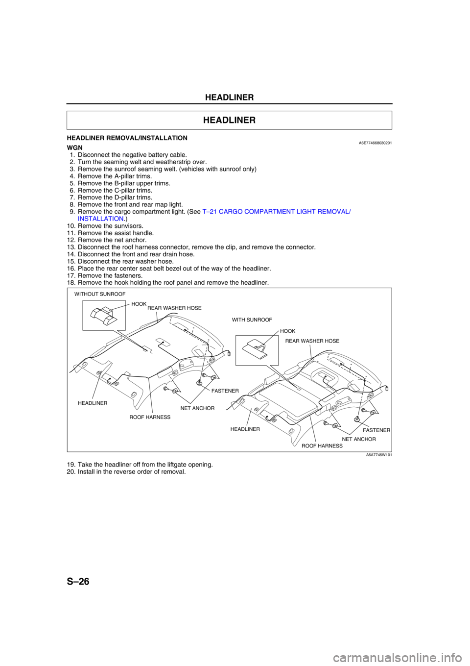
HEADLINER REMOVAL/INSTALLATIONA6E774668030201WGN
1. Disconnect the negative battery cable.
2. Turn the seaming welt and weatherstrip over.
3. Remove the sunroof seaming welt. (vehicles with sunroof only)
4. Remove the A-pillar trims.
5. Remove the B-pillar upper trims.
6. Remove the C-pillar trims.
7. Remove the D-pillar trims.
8. Remove the front and rear map light.
9. Remove the cargo compartment light. (See T–21 CARGO COMPARTMENT LIGHT REMOVAL/
INSTALLATION.)
10. Remove the sunvisors.
11. Remove the assist handle.
12. Remove the net anchor.
13. Disconnect the roof harness connector, remove the clip, and remove the connector.
14. Disconnect the front and rear drain hose.
15. Disconnect the rear washer hose.
16. Place the rear center seat belt bezel out of the way of the headliner.
17. Remove the fasteners.
18. Remove the hook holding the roof panel and remove the headliner.
19. Take the headliner off from the liftgate opening.
20. Install in the reverse order of removal.
End Of Sie
HEADLINER
HOOK
FASTENER
FASTENER ROOF HARNESS HEADLINERHOOK
ROOF HARNESS HEADLINER WITHOUT SUNROOF
WITH SUNROOF REAR WASHER HOSE
REAR WASHER HOSE
NET ANCHOR NET ANCHOR
A6A7746W101
Page 808 of 909

FLOOR COVERING
S–27
S
FRONT FLOOR COVERING REMOVAL/INSTALLATIONA6E774868670201WGN
1. Disconnect the negative battery cable.
2. Remove the front seats.
3. Remove the rear seat. (SeeS–29 REAR SEAT REMOVAL/INSTALLATION)
4. Remove the front scuff plates.
5. Remove the rear scuff plates.
6. Remove the console.
7. Remove the front side trims.
8. Remove the B-pillar lower trims.
9. Remove the lower anchor of the front seat belt installation bolts.
10. Remove the tire house trim.
11. Remove the fuel-filler lid opener bezel.
12. Remove the fasteners.
13. Remove the cap nuts.
14. Remove the clips.
15. Take the front floor covering off from the
passenger-side door opening.
16. Install in the reverse order of removal.
End Of Sie
FLOOR COVERING
FLOOR MATCLIPCAP NUT FASTENER
A6E77481101
Page 809 of 909

S–28
SEAT BELT
REAR SIDE SEAT BELT REMOVAL/INSTALLATIONA6E775057730201
Caution
•The rear side seat belt for 4WD models is equipped with a silencer to reduce abnormal noise while
driving. If the silencer is not installed in the proper position, the push knob may not function
properly. When attaching the silencer, be sure to attach it in the correct area as shown below.
Note
•Rear side seat belts are built into the rear seat back. See rear seat disassembly/assembly, to remove/
install the rear side seat belt.
1. Peel off the backing of the double-sided adhesive tape.
2. Attach double-sided adhesive tape to the silencer as shown.
End Of Sie
REAR CENTER SEAT BELT REMOVAL/INSTALLATIONA6E775057730202WGN
Caution
•The ELR has a spring that will unwind if the retractor's cover is removed. The spring cannot be
rewound by hand. If this occurs, the ELR will not work properly. Therefore, do not disassemble the
retractor.
1. Remove the headliner.
2. Remove the bolts.
3. Remove the rear center seat belt.
4. Install in the reverse order of removal.
End Of Sie
SEAT BELT
SILENCERRETRACTOR
mm {in} 29—35
{1.2—1.3}
-3—3
{-0.1—0.1} 60
{2.3} 60
{2.3}
60
{2.3}
60
{2.3}40
{1.5}
29—35
{1.2—1.3}
-3—3
{-0.1—0.1}
SILENCER RETRACTOR
60{2.3}
A6E77502101
39—78 N·m
{3.9—8.0 kgf·m, 29—57 ft·lbf}
REAR CENTER
SEAT BELT
BOLT
A6A7750W101
Page 810 of 909

SEAT
S–29
S
REAR SEAT REMOVAL/INSTALLATIONA6E7752572002014WD (WGN)
1. Remove in the order indicated in the table.
2. Install in the reverse order of removal.
.
Remote wire removal note
1. Turn over the trunk floor mat.
2. Remove the case.
3. Remove the remote wire.
End Of Sie
SEAT
3
2
1
1
A: 36.3—53.9 N·m
{3.71—5.49 kgf·m, 26.8—39.7 ft·lbf}
B: 38.3—78.4 N·m
{3.91—7.99 kgf·m, 28.3—57.8 ft·lbf}
A
A
B
B
A6E77521102
1 Remote wire
(See S–29 Remote wire removal note)2 Rear seat cushion
3 Rear seat back
CASE
REMOTE WIRE
A6E7752W014