MAZDA 626 1987 Workshop Manual
Manufacturer: MAZDA, Model Year: 1987,
Model line: 626,
Model: MAZDA 626 1987
Pages: 1865, PDF Size: 94.35 MB
MAZDA 626 1987 Workshop Manual
626 1987
MAZDA
MAZDA
https://www.carmanualsonline.info/img/28/57059/w960_57059-0.png
MAZDA 626 1987 Workshop Manual
Trending: lights, wiper fluid, battery, bulb, alternator, roof rack, clutch
Page 1621 of 1865
14 HEADLINER
10. Remove the caps and screws at the ends of the
front header trim.
86U14X-164
11. Remove the caps and screws at the ends of the
rear header trim.
86U14X-165
| 12. Remove the rear side trim.
86U14X-166
13. Remove the seat belt mounting bolts.
86U14X-167
14-70
Page 1622 of 1865
HEADLINER 14
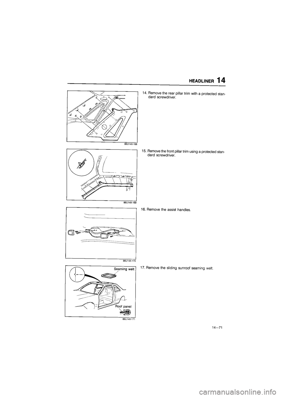
14. Remove the rear pillar trim with a protected stan-
dard screwdriver.
86U14X-168
15. Remove the front pillar trim using a protected stan-
dard screwdriver.
16. Remove the assist handles.
86U14X-170
Seaming welt
J
17, Remove the sliding sunroof seaming welt.
86U14X-171
14-71
Page 1623 of 1865
14 HEADLINER
18. Remove the fasteners and remove the headliner.
86U14X-172
INSTALLATION
Install in the reverse order of removal, noting the fol-
lowing.
Note
Align the trim and clip positions, then install
the clips by striking them lightly.
86U14X-173
14—72
Page 1624 of 1865
INSTRUMENT PANEL 1 4
INSTRUMENT PANEL
STRUCTURAL VIEW
1. Rear console
2. Upper plate.
3. Front console
4. Glove compartment
5. Side cover
6. Side cover
7. Box
8. Ashtray
9. Center panel
10. Heater control assembly
11. Steering wheel cap
12. Steering wheel
13. Column cover
14. Switch panel
76G14X-036
15. Cap
16. Meter hood
17. Duct
18. Duct and under cover
19. Under cover
20. Duct
21. Meter assembly
22. Instrument panel
14—73
Page 1625 of 1865
1 4 INSTRUMENT PANEL
INSTALLATION VIEW
67U14X-003
14—74
Page 1626 of 1865
INSTRUMENT PANEL 1 4
86U14X-175
86U14X-176
REMOVAL
1. Remove the screws and remove the shift lever
knob (ATX).
2. Remove the shift lever knob (MTX).
3. Remove the rear console mounting screws.
4. Pull the console rearward and remove it.
86U14X-178
5. Remove the front console mounting screws.
86U14X-179
14—75
Page 1627 of 1865
1 4 INSTRUMENT PANEL
6. Remove the steering wheel cap.
76G14X-026
7. Remove the steering wheel mounting nut.
76G14X-027
9. Remove the screws and remove the column covers
(upper and lower).
76G14X-028
14—76
Page 1628 of 1865
INSTRUMENT PANEL 1 4
76G14X-029
10. Remove the screws and remove the under covers.
11. Loosen the nut and remove the hood release knob.
76G14X-030
86U14X-185
12. Remove the screws and pull out the meter hood.
13. Disconnect the connectors and remove the meter
hood.
14. Remove the screws and pull the meter assembly
outward.
15. Disconnect the speedometer cable at the
speedometer.
16. Disconnect the gauge connectors.
17. Remove the meter assembly.
86U14X-186
14—77
Page 1629 of 1865
1 4 INSTRUMENT PANEL
86U14X-187
86U14X-188
86U14X-189
18. Remove the screws and pull the panel outward.
19. Disconnect the connectors and remove the switch
panel.
20. Remove the screws and remove the glove box.
21. Disconnect the glove box light connector.
22. Remove the center panel.
23. Remove the screws and slide out the heater con-
trol assembly.
24. Disconnect the control wires at the DEF, MAX-
COLD and REC positions (lever type control).
Note
Disconnect the connectors at the rear of the
control (Logicon type).
25. Remove the center cap.
26. Remove the instrument panel mounting bolt.
86U14X-190
14-78
Page 1630 of 1865
INSTRUMENT PANEL 1 4
27. Remove the instrument panel side mounting bolts.
86U14X-191
28. Remove the instrument panel center bracket
mounting bolts.
86U14X-192
29. Remove the steering shaft mounting bolts.
86U14X-193
30. Disconnect the dash harness connectors.
31. Remove the instrument panel.
86U14X-194
14—79
Trending: sensor, horn, fuse box location, coolant level, open bonnet, ad blue, automatic transmission fluid


