MAZDA 626 1987 Workshop Manual
Manufacturer: MAZDA, Model Year: 1987, Model line: 626, Model: MAZDA 626 1987Pages: 1865, PDF Size: 94.35 MB
Page 1781 of 1865
15 HEATER
86U15X-218
86U15X-219
86U15X-220
r.". 1
T 1 11 1.11 -4
y -L -v* X /
1
C I y
1 A +
Voltmeter
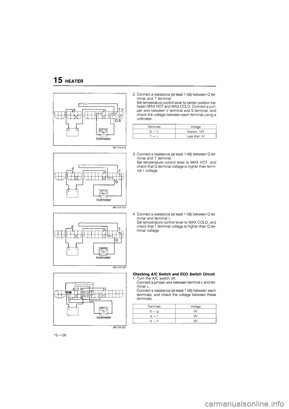
2. Connect a resistance (at least 1 kfi) between Q ter-
minal and T terminal.
Set temperature control lever to center position be-
tween MAX HOT and MAX COLD. Connect a jum-
per wire between V terminal and S terminal, and
check the voltage between each terminal using a
voltmeter.
Terminals Voltage
Q - L Approx. 12V
T - L Less than 1V
3. Connect a resistance (at least 1 kfi) between Q ter-
minal and T terminal.
Set temperature control lever to MAX HOT, and
check that Q terminal voltage is higher than termi-
nal t voltage.
4. Connect a resistance (at least 1 M2) between Q ter-
minal and terminal t.
Set temperature control lever to MAX COLD, and
check that T terminal voltage is higher than Q ter-
minal voltage.
Checking A/C Switch and ECO Switch Circuit
1. Turn the A/C switch off.
Connect a jumper wire between terminal c and ter-
minal L.
Connect a resistance (at least 1 kQ) between each
terminals, and check the voltage between these
terminals.
Terminals Voltage
d-g OV
d - f OV
d - h OV
86U15X-221
15-126
Page 1782 of 1865
HEATER 15
f! !"H
a
+
1 d-V' X /
S3
Voltmeter
86U15X-222
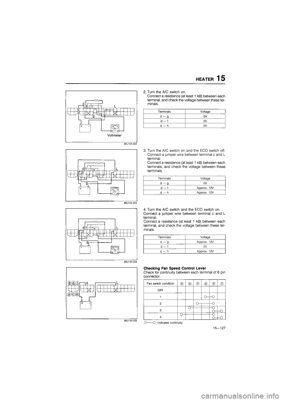
2. Turn the A/C switch on.
Connect a resistance (at least 1 kQ) between each
terminal, and check the voltage between these ter-
minals.
Terminals Voltage
d-g OV
d
- f
OV
d
- h
OV
d I—T-
fjrh
X }
®(dxr
X /
86U15X-223
d fi riTu~"! 1 L r-
k J M > < / —IC
7 T — 101 [oOrv
86U15X-224
X
86U15X-225
3. Turn the A/C switch on and the ECO switch off.
Connect a jumper wire between terminal c and L
terminal.
Connect a resistance (at least 1 kQ) between each
terminals, and check the voltage between these
terminals.
Terminals Voltage
d-g OV
d
- f
Approx.
12V
d
- h
Approx.
12V
4. Turn the A/C switch and the ECO switch on.
Connect a jumper wire between terminal c and L
terminal.
Connect a resistance (at least 1 kQ) between each
terminal, and check the voltage between these ter-
minals.
Terminals Voltage
d-g Approx.
12V
d
- f
OV
d
- h
Approx.
12V
Checking Fan Speed Control Lever
Check for continuity between each terminal of 6 pin
connector.
Fan switch condition
® ® © @ © ©
OFF
1
2 O--O
3 O--O O— -O
4 O--O O--O
o
-O: indicates continuity
15-127
Page 1783 of 1865

15 HEATER
i l< i |l
k J X / X X L<
1 +
L<
1 + 1
Checking Dim Indicator Circuits
(Indicator circuit)
1. Connect a jumper wire-between terminal c and ter-
minal L.
Check for illumination at A/C switch indicator with
A/C switch on.
Check for illumination at ECO switch indicator with
ECO switch on.
86U15X-226
d 1 |L
k J X / I k
1 Jl +
2. Check that the mode control switch and REC-
FRESH select switch indicators when the respec-
tive switches ON.
86U15X-227
3. Apply 12V to terminal a, and check that the indi-
cators are dim.
86U15X-228
b —id 1 L
1 1 j
k XI N_ > < / a
ir
Checking Illumination Circuit
1. Connect a jumper wire between terminal b and ter-
minal L.
2. Apply 12V to terminal a, and check that the indi-
cators are dim.
86U15X-229
15-128
Page 1784 of 1865

16
AIR CONDITIONING
SYSTEM
OUTLINE 16— 2
AIR DISTRIBUTION 16— 2
AIR CONDITIONING COMPONENTS 16— 4
TROUBLESHOOTING GUIDE 16— 5
CIRCUIT DIAGRAM 16— 6
REFRIGERATION SYSTEM 16— 8
COMPRESSOR 16—13
ON-VEHICLE INSPECTION 16—13
REMOVAL OF COMPRESSOR 16—13
DISASSEMBLY OF MAGNETIC
CLUTCH 16—14
DISASSEMBLY OF COMPRESSOR 16—16
ASSEMBLY OF COMPRESSOR 16—18
ASSEMBLY OF MAGNETIC CLUTCH 16—20
PERFORMANCE TEST OF
COMPRESSOR 16—22
INSTALLATION OF COMPRESSOR 16—23
CONDENSER 16—24
ON-VEHICLE INSPECTION 16—24
REMOVAL OF CONDENSER 16—24
INSTALLATION OF CONDENSER.. 16—24
RECEIVER-DRIER 16—25
ON-VEHICLE INSPECTION 16—25
REMOVAL OF RECEIVER-DRIER... 16—25
INSTALLATION OF
RECEIVER-DRIER 16—25
COOLING UNIT 16—26
ON-VEHICLE INSPECTION OF
EXPANSION VALVE 16—26
REMOVAL OF COOLING UNIT 16—26
DISASSEMBLY OF COOLING UNIT 16—27
INSPECTION OF EVAPORATOR.... 16—27
ASSEMBLY OF COOLING UNIT.... 16—27
INSTALLATION OF COOLING UNIT 16—28
REFRIGERANT LINES 16—29
ON-VEHICLE INSPECTION 16—29
REPLACEMENT OF REFRIGERANT
LINES 16—29
A/C RELAY 16—30
REMOVAL OF RELAY 16—30
INSPECTION OF A/C RELAY 16—30
INSTALLATION OF A/C RELAY 16—30
THERMOSTAT 16—30
ON-VEHICLE INSPECTION 16—30
REMOVAL OF THERMOSTAT 16-30
INSTALLATION OF THERMOSTAT. 16—30
REFRIGERANT PRESSURE SWITCH 16—31
76G16X-001
Page 1785 of 1865

16 OUTLINE
OUTLINE
AIR DISTRIBUTION
Vehicles with air conditioner
Side ventilator outlet
1
Center ventilator outlet
- Defroster = outlet
FRESH air inlet
REC air inlet
Side . ventilator < outlet
Floor outlet
Temperature control lever
*
REC-FRESH air selector lever
•QDOODDDaaacziciz) ^^^ ° cQ^
^J 'i, *
OFF
1 7 3 4
Mode control lever
Mode control switch
A/C
DECO
Blower switch
REC-FRESH air selector switch
«?/ ^ W ^
izzi • izn •
C^) A/C - ECDN
• CUD
<=i ac3 a ua • • Jf OFF 12 3 4. SJ
Temperature control lever Blower switch
69G16X002
16-2
Page 1786 of 1865
OUTLINE 16
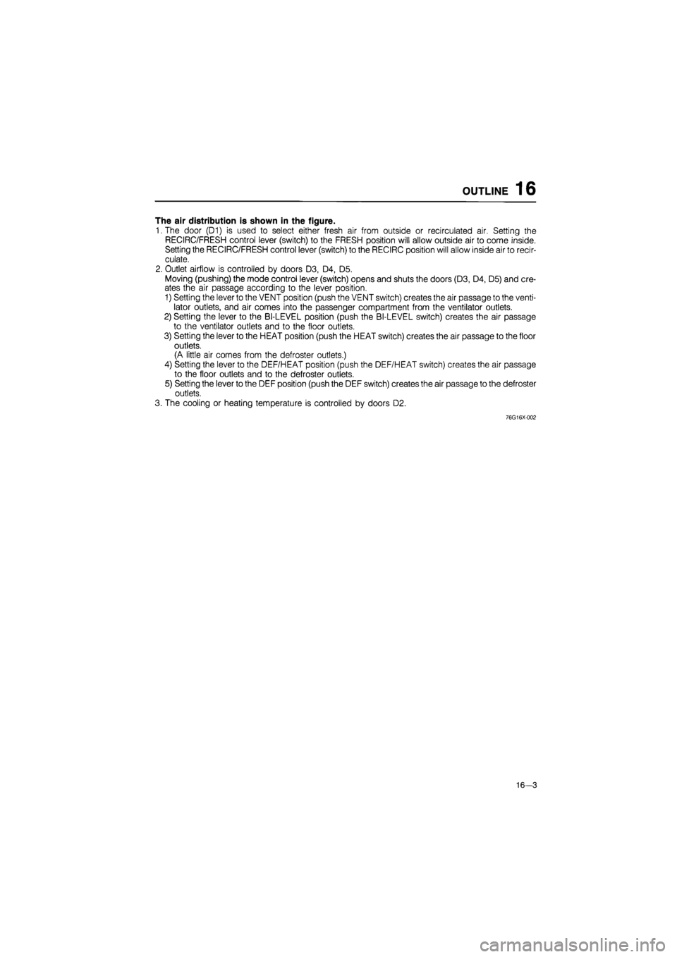
The air distribution is shown in the figure.
"I.The door (D1) is used to select either fresh air from outside or recirculated air. Setting the
RECIRC/FRESH control lever (switch) to the FRESH position will allow outside air to come inside.
Setting the RECIRC/FRESH control lever (switch) to the RECIRC position will allow inside air to recir-
culate.
2. Outlet airflow is controlled by doors D3, D4, D5.
Moving (pushing) the mode control lever (switch) opens and shuts the doors (D3, D4, D5) and cre-
ates the air passage according to the lever position.
1) Setting the lever to the VENT position (push the VENT switch) creates the air passage to the venti-
lator outlets, and air comes into the passenger compartment from the ventilator outlets.
2) Setting the lever to the BI-LEVEL position (push the BI-LEVEL switch) creates the air passage
to the ventilator outlets and to the floor outlets.
3) Setting the lever to the HEAT position (push the HEAT switch) creates the air passage to the floor
outlets.
(A little air comes from the defroster outlets.)
4) Setting the lever to the DEF/HEAT position (push the DEF/HEAT switch) creates the air passage
to the floor outlets and to the defroster outlets.
5) Setting the lever to the DEF position (push the DEF switch) creates the air passage to the defroster
outlets.
3. The cooling or heating temperature is controlled by doors D2.
76G16X-002
16-3
Page 1787 of 1865
16 OUTLINE
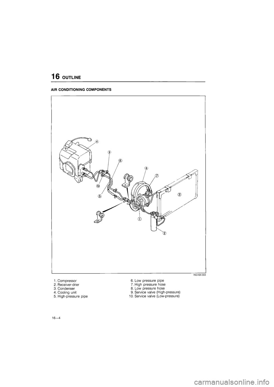
AIR CONDITIONING COMPONENTS
76G16X-003
1. Compressor 6. Low pressure pipe
2. Receiver-drier 7. High pressure hose
3. Condenser 8. Low pressure hose
4. Cooling unit 9. Service valve (High-pressure)
5. High-pressure pipe 10. Service valve (Low-pressure)
16—4
Page 1788 of 1865
OUTLINE 16
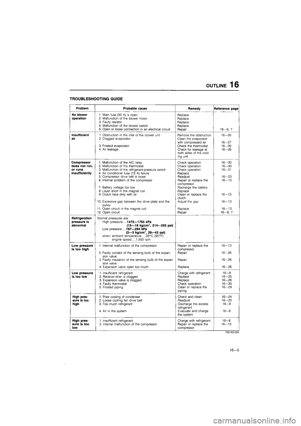
TROUBLESHOOTING GUIDE
Problem Probable cause Remedy Reference page
No blower
1. Main fuse (30
A) is
open Replace
operation
2 Malfunction
of
the blower motor Replace 3. Faulty resistor Replace 4. Malfunction
of
the blower switch Replace 5. Open
or
loose connection
in an
electrical circuit Repair 16—6,
7
Insufficient
1. Obstruction
in
the inlet
of
the blower unit Remove the obstruction 16-26
air
2. Clogged evaporator Clean the evaporator
with compressed
air
16-27 3. Frosted evaporator Check the thermostat 16-30 4. Air leakage Check for leakage
at
16-26 both sides
of
the cool-
ing unit
Compressor
1. Malfunction
of
the A/C relay Check operation 16—30
does not run,
2. Malfunction
of
the thermostat Check operation 16—30
or runs
3. Malfunction
of
the refrigerant-pressure switch Check operation 16—31
insufficiently
4.
Air
conditioner fuse (15
A)
failure Replace 5. Compressor drive belt
is
loose Readjust 16—23
6. Internal problem
of
the compressor Repair
or
replace
the
16—13
compressor 7. Battery voltage too low Recharge the battery 8. Layer short
in
the magnet coil Replace 9. Clutch face dirty with
oil
Clean
or
replace the 16-13
clutch 10. Excessive gap between the drive plate and
the
Adjust the gap 16-13
pulley
11. Open circuit
in
the magnet coil Replace 16—13
12 Open circuit Repair 16-6,
7
Refrigeration
Normal pressures are:
pressure is
High pressure
1472—1765 kPa
abnormal (15—18 kg/cm2, 214—255 psi)
Low pressure
197—294 kPa
(2—3 kg/cm2, 29—42 psi)
when: ambient temperature 35°C (95°F)
engine speed 1,500
rpm
Low pressure
1. Internal malfunction
of
the compressor Repair
or
replace the 16-13
is too high
compressor
2. Faulty contact
of
the sensing bulb
of
the expan-Repair 16-26
sion valve 3. Faulty insulation
of
the sensing bulb
of
the expan-Repair 16—26
sion valve
4. Expansion valve open too much Replace 16—26
Low pressure
1. Insufficient refrigerant Charge with refrigerant 16-8
is too low
2. Receiver-drier
is
clogged Replace 16-25
3. Expansion valve
is
clogged Replace 16-26
4. Faulty thermostat Check operation 16-30 5. Frosted piping Clean
or
replace the 16—29
piping
High pres-
1. Poor cooling
of
condenser Check and clean 16-24
sure is too
2. Loose cooling fan drive belt Readjust 16—23
high
3. Too much refrigerant Discharge the excess 16-8
refrigerant 4.
Air in
the system Evacuate and charge 16-8
the system
High pres-
1. Insufficient refrigerant Charge with refrigerant 16-8
sure is too
2. Internal malfunction
of
the compressor Repair
or
replace the 16-13
low
compressor
76G16X-004
16—5
Page 1789 of 1865
16 OUTLINE
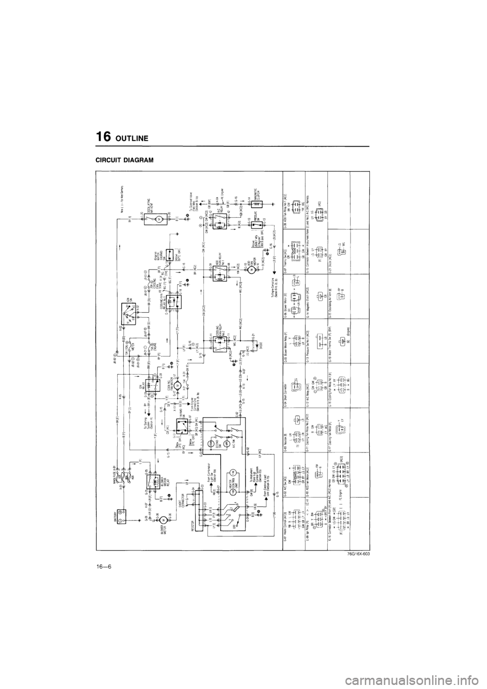
CIRCUIT DIAGRAM
76G16X-603
16—6
Page 1790 of 1865
OUTLINE
16
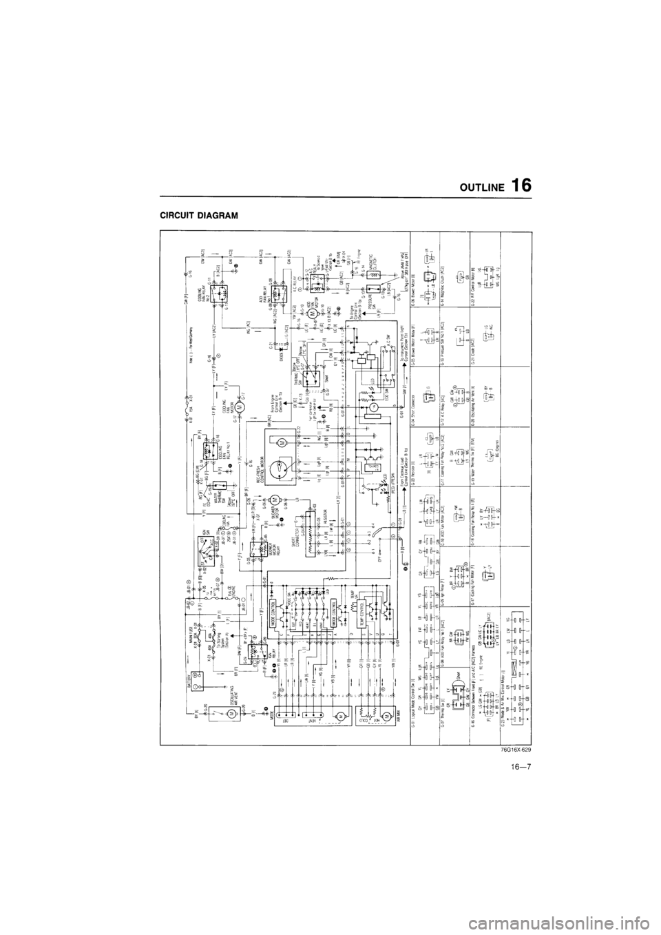
CIRCUIT DIAGRAM
76G16X-629
16—7