MAZDA 626 1987 Workshop Manual
Manufacturer: MAZDA, Model Year: 1987, Model line: 626, Model: MAZDA 626 1987Pages: 1865, PDF Size: 94.35 MB
Page 181 of 1865

1 B ASSEMBLY (CYLINDER BLOCK)
Spacer tang
Oil ring
spacer ends
Upper rail
Piston
Lower rail
69G01A-145
86U01X-121
Oil ring —
upper rail / N. ^ Top ring
Oil ring I ^_t30° L^Pistion
T Pin spacer I ^_t30° L^Pistion
T Pin
Oil ring
lower rail N. j/ Second ring
69G01A-147
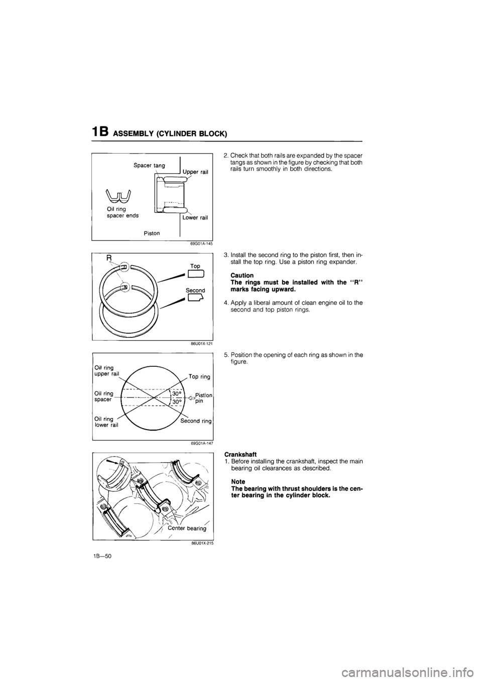
2. Check that both rails are expanded by the spacer
tangs as shown in the figure by checking that both
rails turn smoothly in both directions.
3. Install the second ring to the piston first, then in-
stall the top ring. Use a piston ring expander.
Caution
The rings must be installed with the "R"
marks facing upward.
4. Apply a liberal amount of clean engine oil to the
second and top piston rings.
5. Position the opening of each ring as shown in the
figure.
Crankshaft
1. Before installing the crankshaft, inspect the main
bearing oil clearances as described.
Note
The bearing with thrust shoulders is the cen-
ter bearing in the cylinder block.
86U01X-136
1B—50
Page 182 of 1865

ASSEMBLY (CYLINDER BLOCK) 1 B
Oil clearance inspection
(1) Remove any foreign material and oil from the
journals and bearings.
(2) Install the upper main bearings in the cylinder
block.
(3) Set the crankshaft into the cylinder block.
(4) Position the plasti-gauge on top of the journals
in the axial direction.
86U01X-122
(5) Install the main bearing caps along with the
lower main bearings according to the cap num-
ber and mark.
(6) Tighten the caps in two or three steps in the
order in the figure.
Tightening torque:
82—88 Nm (8.4—9.0 m-kg, 61—65 ft-lb)
Caution
Do not rotate the crankshaft when measuring
the oil clearances.
86U01X-123
(7) Remove the main bearing caps, and measure
the plasti-gauge at each journal at the widest
point for the smallest clearance, and at the nar-
rowest point for the largest clearance.
If the oil clearance exceeds specification, grind
the crankshaft and use undersize main bear-
ings. (Refer to page 1B—45.)
Oil clearance
No. 1, 2, 4, 5:
0.025—0.043 mm (0.0010—0.0017 in)
No. 3:
0.031—0.049 mm (0.0012—0.0019 in)
Maximum: 0.08 mm (0.0031 in)
Apply a liberal amount of engine oil to the main
bearings and main journals.
Install the crankshaft and the main bearing caps
according to the cap number and ^ mark.
86U01X-125
1B—51
Page 183 of 1865

1 B ASSEMBLY (CYLINDER BLOCK)
76G01A-074
86U01X-216
76G01 B-075
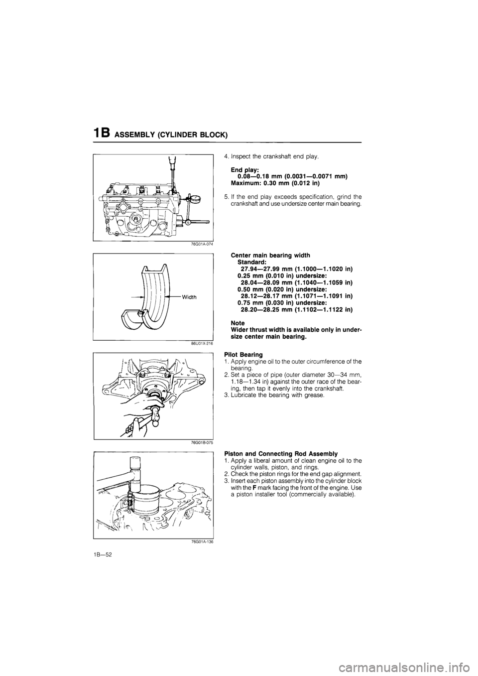
4. Inspect the crankshaft end play.
End play:
0.08—0.18 mm (0.0031—0.0071 mm)
Maximum: 0.30 mm (0.012 in)
5. If the end play exceeds specification, grind the
crankshaft and use undersize center main bearing.
Center main bearing width
Standard:
27.94—27.99 mm (1.1000—1.1020 in)
0.25 mm (0.010 in) undersize:
28.04—28.09 mm (1.1040—1.1059 in)
0.50 mm (0.020 in) undersize:
28.12—28.17 mm (1.1071—1.1091 in)
0.75 mm (0.030 in) undersize:
28.20—28.25 mm (1.1102—1.1122 in)
Note
Wider thrust width is available only in under-
size center main bearing.
Pilot Bearing
1. Apply engine oil to the outer circumference of the
bearing.
2. Set a piece of pipe (outer diameter 30—34 mm,
1.18—1.34 in) against the outer race of the bear-
ing, then tap it evenly into the crankshaft.
3. Lubricate the bearing with grease.
Piston and Connecting Rod Assembly
1. Apply a liberal amount of clean engine oil to the
cylinder walls, piston, and rings.
2. Check the piston rings for the end gap alignment.
3. Insert each piston assembly into the cylinder block
with the F mark facing the front of the engine. Use
a piston installer tool (commercially available).
76G01A-136
1B—52
Page 184 of 1865

ASSEMBLY (CYLINDER BLOCK) 1 B
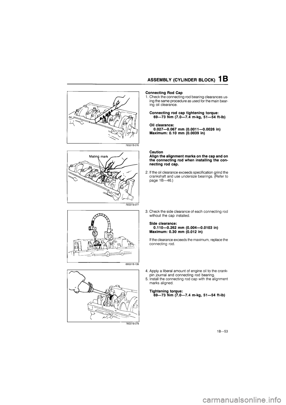
Connecting Rod Cap
1. Check the connecting rod bearing clearances us-
ing the same procedure as used for the main bear-
ing oil clearance.
Connecting rod cap tightening torque:
69—73 Nm (7.0—7.4 m-kg, 51—54 ft-lb)
Oil clearance:
0.027—0.067 mm (0.0011—0.0026 in)
Maximum: 0.10 mm (0.0039 in)
76G01B-076
Caution
Align the alignment marks on the cap and on
the connecting rod when installing the con-
necting rod cap.
2. If the oil clearance exceeds specification grind the
crankshaft and use undersize bearings. (Refer to
page 1B—46.)
76G01B-077
3. Check the side clearance of each connecting rod
without the cap installed.
Side clearance:
0.110—0.262 mm (0.004—0.0103 in)
Maximum: 0.30 mm (0.012 in)
If the clearance exceeds the maximum, replace the
connecting rod.
69G01B-139
4. Apply a liberal amount of engine oil to the crank-
pin journal and connecting rod bearing.
5. Install the connecting rod cap with the alignment
marks aligned.
Tightening torque:
69—73 Nm (7.0—7.4 m-kg, 51—54 ft-lb)
76G01B-078
1B—53
Page 185 of 1865

1 B ASSEMBLY (CYLINDER BLOCK)
CYLINDER BLOCK—II
Torque Specifications
19—25 N m (1.9—2.6 m-kg, 14-19 ft-lb)
7—12 N'm (70—120 cm-kg, 61—104 in-lb)
69G01A-166
Rear Cover
1. Apply engine oil to the rear cover, oil seal and oil
seal lip.
2. Press the oil seal into the rear cover.
4BG01A-158
1B—54
Page 186 of 1865

ASSEMBLY (CYLINDER BLOCK) 1 B
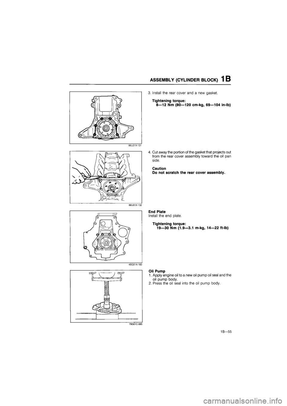
3. Install the rear cover and a new gasket.
Tightening torque:
8—12 N-m (80—120 cm-kg, 69—104 in-lb)
86U01X-131
4. Cut away the portion of the gasket that projects out
from the rear cover assembly toward the oil pan
side.
Caution
Do not scratch the rear cover assembly.
86U01X-132
End Plate
Install the end plate.
Tightening torque:
19—30 Nm (1.9—3.1 m-kg, 14—22 ft-lb)
4BG01A-160
Oil Pump
1. Apply engine oil to a new oil pump oil seal and the
oil pump body.
2. Press the oil seal into the oil pump body.
79G01C-085
1B—55
Page 187 of 1865

1 B ASSEMBLY (CYLINDER BLOCK)
3. Apply engine oil to the oil seal lip.
4. Remove any dirt or other material from the con-
tact surfaces.
5. Apply a continuos bead of silicon sealant to the
contact surface of the oil pump.
Caution
Do not allow any sealant to get into the oil
hole.
86U01X-133
6. Install a new O-ring into the pump body.
7. Install the oil pump.
Tightening torque
(A):
19—25
N
m
(1.9—2.6 m-kg, 14—19 ft-lb)
(§): 37—52
N
m
(3.8—5.3 m-kg, 27—38 ft-lb)
8. Remove any sealant which has been squeezed
out.
76G01A-137
Oil Jet
Install the oil jet as shown in the figure.
Tightening torque: 12—18 Nm
(1.2—1.8 m-kg, 104—156 in-lb)
Caution
The shapes of the No.1, 3 cylinders jet valves
and No.2, 4 jet valves are different.
76G01B-079
Oil Strainer
Install the oil strainer and a new gasket.
Tightening torque:
8—12 Nm (80—120 cm-kg, 69—104 in-lb)
86U01X-136
1B—56
Page 188 of 1865

ASSEMBLY (CYLINDER BLOCK) 1 B
Oil Pan
1. Apply a continuous bead of silicon sealant to the
oil pan around inside of the bolt holes and over-
lap the ends.
2. Install the oil pan.
Tightening torque:
7—12 Nm (70—120 cm-kg, 61—104 in-lb)
Caution
Oil pan projection and recession from the end
of the cylinder block must not be more than
1.5 mm (0.06 in).
76G01 B-080
Flywheel
1. Remove any old sealant from the bolts and bolt
holes. If old sealant can not be removed from the
bolt, replace it.
2. Apply sealant to the bolt threads.
76G01B-081
3. Install, and tighten the flywheel with the SST.
Tightening torque:
96—103
N
m (9.8—10.5 m-kg, 71—76 ft-lb)
76G01B-082
Clutch Disc and Clutch Cover
Install the clutch disc and clutch cover using the SST.
(Refer to Section 6.)
Tightening torque:
22—32
N m
(2.2—3.3 m-kg, 16—24 ft-lb)
76G01 B-083
1B—57
Page 189 of 1865

1 B ASSEMBLY (CYLINDER BLOCK)
Water Pump
1. Remove all dirt, grease, and other material from
the water pump mounting surface.
2. Place a new O-ring in position.
Caution
Do not reuse the original O-ring.
86U01X-142
3. Install the water pump.
Tightening torque:
19—25 Nm (1.9—2.6 m-kg, 14—19 ft-lb)
7BU01B-103
1B-58
Page 190 of 1865

ASSEMBLY (CYLINDER
BLOCK)
1 B
CYLINDER HEAD
Torque Specifications
18—26 N-m (1.8—2.7 m-kg, 13—20 ft-lb)
8—12 Nm (80—120 cm-kg, 69—104 in-lb)
4—6 Nm (40—60 cm-kg, 35—52 In-lb)
69G01B-152
49 G012 002
Valve Seal
1. Apply engine oil to the inside of the new valve seal.
2. Install the valve seal onto the valve guide with the
SST
76G01 B-083
1B—59