MAZDA 626 1987 Workshop Manual
Manufacturer: MAZDA, Model Year: 1987, Model line: 626, Model: MAZDA 626 1987Pages: 1865, PDF Size: 94.35 MB
Page 211 of 1865
1B INSTALLATION
76G01B-113
76G01B-114
76G01B-115
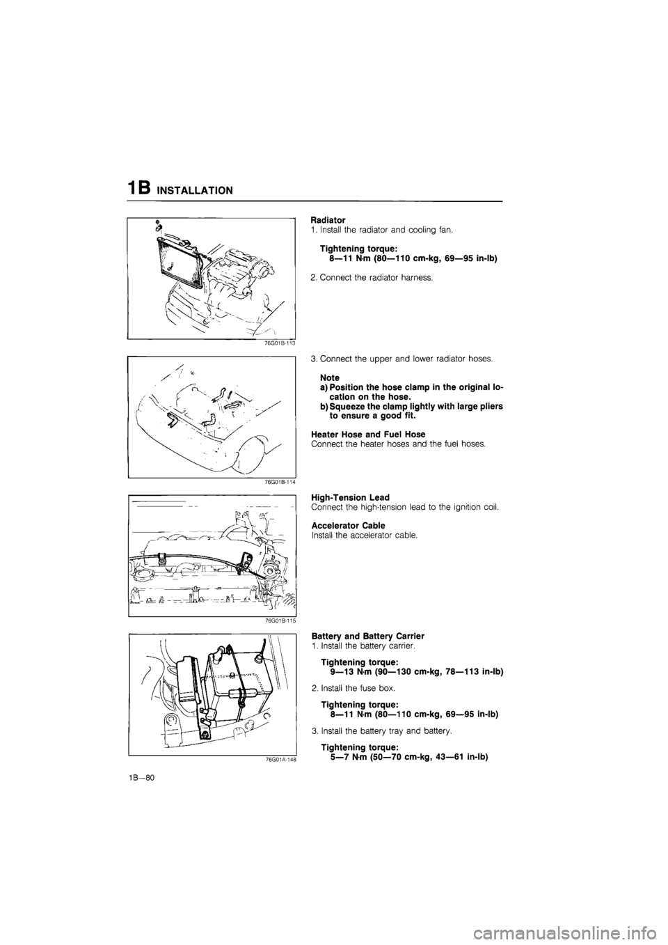
Radiator
1. Install the radiator and cooling fan.
Tightening torque:
8—11 N-m (80—110 cm-kg, 69—95 in-lb)
2. Connect the radiator harness.
3. Connect the upper and lower radiator hoses.
Note
a) Position the hose clamp in the original lo-
cation on the hose.
b) Squeeze the clamp lightly with large pliers
to ensure a good fit.
Heater Hose and Fuel Hose
Connect the heater hoses and the fuel hoses.
High-Tension Lead
Connect the high-tension lead to the ignition coil.
Accelerator Cable
Install the accelerator cable.
76G01A-148
Battery and Battery Carrier
1. Install the battery carrier.
Tightening torque:
9—13 N-m (90—130 cm-kg, 78—113 in-lb)
2. Install the fuse box.
Tightening torque:
8—11
N
m (80—110 cm-kg, 69—95 in-lb)
3. Install the battery tray and battery.
Tightening torque:
5_7
N m
(50—70 cm-kg, 43—61 in-lb)
1B—80
Page 212 of 1865
INSTALLATION 1B
76G01A-100
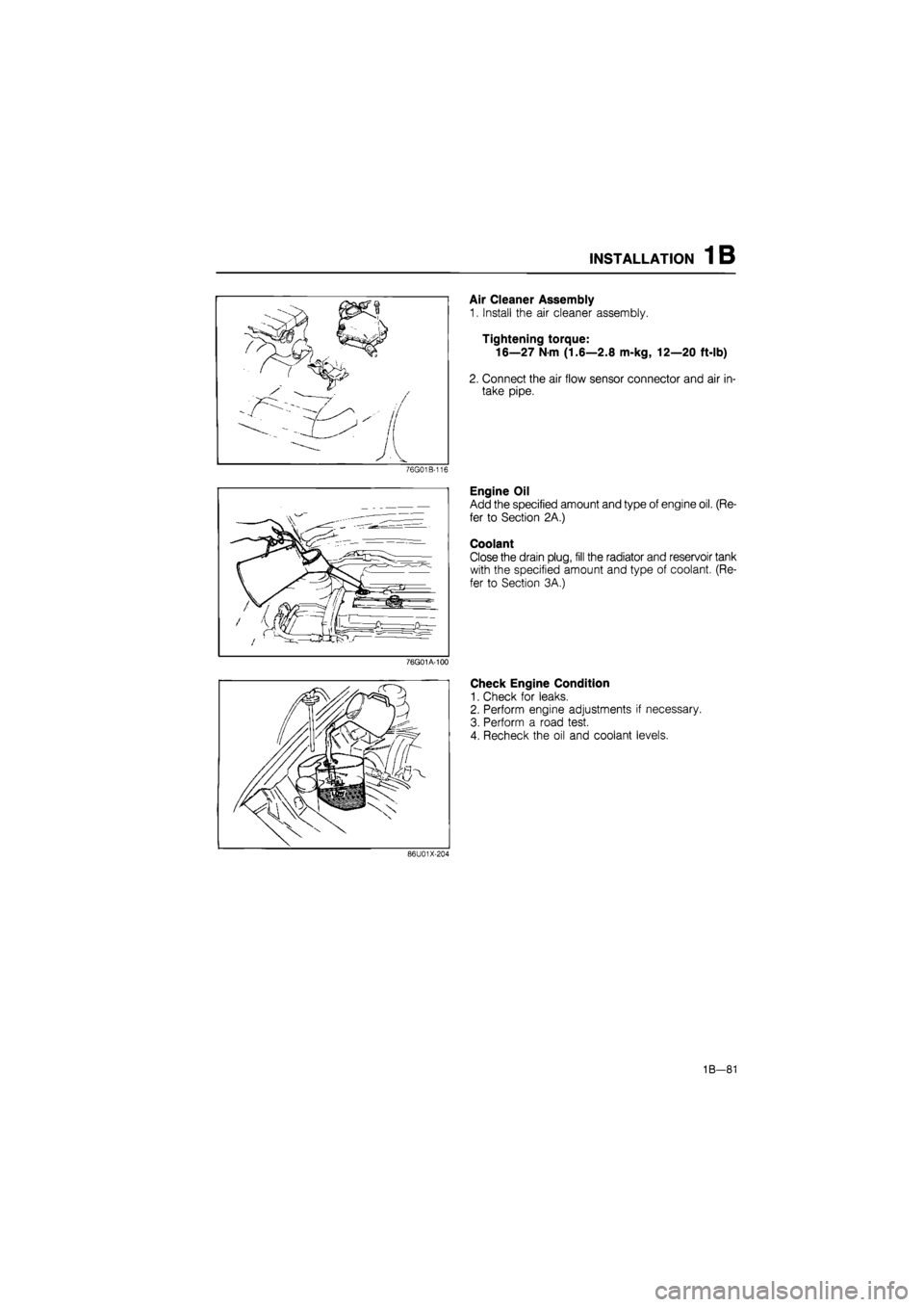
Air Cleaner Assembly
1. Install the air cleaner assembly.
Tightening torque:
16—27
N
m (1.6—2.8 m-kg, 12—20 ft-lb)
2. Connect the air flow sensor connector and air in-
take pipe.
Engine Oil
Add the specified amount and type of engine oil. (Re-
fer to Section 2A.)
Coolant
Close the drain plug, fill the radiator and reservoir tank
with the specified amount and type of coolant. (Re-
fer to Section 3A.)
Check Engine Condition
1. Check for leaks.
2. Perform engine adjustments if necessary.
3. Perform a road test.
4. Recheck the oil and coolant levels.
86U01X-204
1B-81
Page 213 of 1865

ENGINE
(DIESEL)
OUTLINE 1C— 2
STRUCTURAL VIEW 1C— 2
SPECIFICATIONS 1C— 3
TROUBLESHOOTING GUIDE 1C— 3
TUNE-UP PROCEDURE 1C— 5
ON-VEHICLE INSPECTION 1C—10
COMPRESSION 1C—10
ON-VEHICLE MAINTENANCE 1C—11
TIMING BELT 1C—11
CYLINDER HEAD 1C—16
VALVE SEAL 1C—24
REMOVAL 1C—31
DISASSEMBLY 1C—34
AUXILIARY PARTS 1C—34
TIMING BELT 1C—36
INJECTION PUMP 1C—39
CYLINDER HEAD 1C—40
CYLINDER BLOCK 1C—43
INSPECTION AND REPAIR 1C—47
ASSEMBLY 1C—62
CYLINDER BLOCK 1C—62
CYLINDER HEAD 1C—73
INJECTION PUMP 1C—78
TIMING BELT 1C—81
AUXILIARY PARTS 1C—87
INSTALLATION 1C—91
TRANSAXLE ASSEMBLY 1C—91
ENGINE INSTALLATION 1C—92 76G01C-001
Page 214 of 1865

1C OUTLINE
OUTLINE
STRUCTURAL VIEW
1C-2
4BG01A-002
Page 215 of 1865

TROUBLESHOOTING GUIDE 1 C
SPECIFICATIONS
———Engine model
Item ^—_______ RF-CX RF-N
Type Diesel, 4 cycle
Cylinder arrangement and number In line, 4 cylinders
Combustion chamber Swirl chamber
Valve system OHC, belt driven
Displacement cc (cu in) 1,998 (121.9)
Bore and stroke mm (in) 86.0 x 86.0 (3.39 x 3.39)
Compression ratio 21.1 : 1 22.7 : 1
Compression pressure
kPa (kg/cm2, psi)-rpm
Standard 2.943 (30, 427)-200 Compression pressure
kPa (kg/cm2, psi)-rpm Minimum 2.649 (27, 384)-200
Valve timing
IN Open BTDC 13° 13°
Valve timing
IN Close ABDC 15° 39° Valve timing
EX Open BBDC 60° 60° Valve timing
EX Close ATDC 8° 8°
Valve clearance mm (in)
Cold IN 0.25 (0.010)
Valve clearance mm (in)
Cold EX 0.35 (0.014) Valve clearance mm (in) Warm (for ref.)
IN 0.30 (0.012) Valve clearance mm (in) Warm (for ref.) EX 0.40 (0.016)
Idle speed (MTX in neutral) rpm 720
Injection timing ATDC 10 TDC 0°
Injection order 1_3_4_2
76G01C-002
TROUBLESHOOTING GUIDE
Problem Possible Cause Remedy Page
Difficult starting Malfunction of engine-related components
Burned valve Worn piston, piston ring, or cylinder Failed cylinder head gasket
Replace Replace or repair Replace
1C-48 1C—55,56 1C-16
Difficult starting
Malfunction of fuel system Refer to Section 4D
Difficult starting
Malfunction of Comprex supercharger Refer to Section 4D
Difficult starting
Malfunction of electrical system Refer to Section 5
Poor idling Malfunction of engine-related components Improper valve clearance Poor valve to valve seat contact Failed cylinder head gasket
Adjust Repair or replace Replace
1C-85 1C-50 1C—16
Poor idling
Malfunction of fuel system Refer to Section 4D
Poor idling
Malfunction of Comprex supercharger Refer to Section 4D
Excessive oil consumption
Oil working up Worn piston ring groove or sticking piston ring Worn piston or cylinder
Replace Replace or repair
1C-57 1C—55,56
Excessive oil consumption
Oil working down Worn valve seal Worn valve stem or guide
Replace Replace
1C-24 1C-48
Excessive oil consumption
Oil leakage Refer to Section 2B
76G01C-003
1C—3
Page 216 of 1865
1 C TROUBLESHOOTING GUIDE
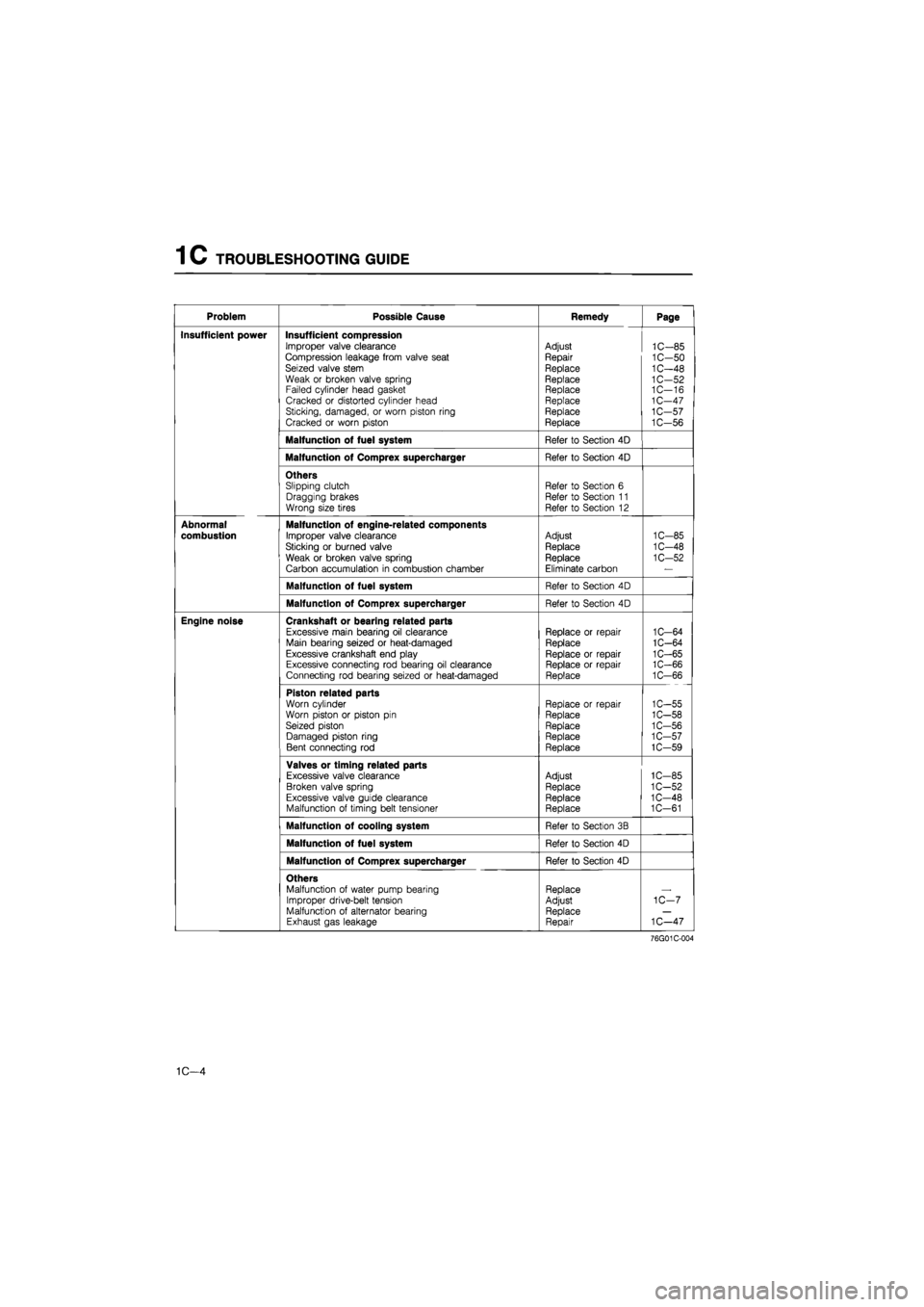
Problem Possible Cause Remedy Page
Insufficient power Insufficient compression Improper valve clearance Compression leakage from valve seat Seized valve stem Weak or broken valve spring Failed cylinder head gasket Cracked or distorted cylinder head Sticking, damaged, or worn piston ring Cracked or worn piston
Adjust
Repair
Replace Replace Replace Replace Replace Replace
1C-85 1C-50 1C-48 1C-52 1C—16 1C-47 1C-57 1C-56
Malfunction of fuel system Refer to Section 4D
Malfunction of Comprex supercharger Refer to Section 4D
Others Slipping clutch Dragging brakes Wrong size tires
Refer to Section 6 Refer to Section 11 Refer to Section 12
Abnormal
combustion
Malfunction of engine-related components
Improper valve clearance
Sticking or burned valve
Weak or broken valve spring
Carbon accumulation in combustion chamber
Adjust
Replace
Replace Eliminate carbon
1C-85
1C-48
1C-52
Malfunction of fuel system Refer to Section 4D
Malfunction of Comprex supercharger Refer to Section 4D
Engine noise Crankshaft or bearing related parts Excessive main bearing oil clearance Main bearing seized or heat-damaged Excessive crankshaft end play Excessive connecting rod bearing oil clearance Connecting rod bearing seized or heat-damaged
Replace or repair Replace
Replace or repair Replace or repair Replace
1C-64 1C-64 1C-65 1C-66 1C-66
Piston related parts Worn cylinder Worn piston or piston pin Seized piston Damaged piston ring Bent connecting rod
Replace or repair Replace
Replace Replace Replace
1C-55 1C-58 1C-56 1C-57 1C-59
Valves or timing related parts Excessive valve clearance Broken valve spring Excessive valve guide clearance Malfunction of timing belt tensioner
Adjust Replace Replace Replace
1C-85 1C-52 1C-48 1C-61
Malfunction of cooling system Refer to Section 3B
Malfunction of fuel system Refer to Section 4D
Malfunction of Comprex supercharger Refer to Section 4D
Others Malfunction of water pump bearing Improper drive-belt tension Malfunction of alternator bearing Exhaust gas leakage
Replace Adjust Replace Repair
1C-7
1C—47
76G01C-004
1C—4
Page 217 of 1865
TUNE-UP PROCEDURE 1C
4BG01 B-006
4BG01B-007
76G01C-237
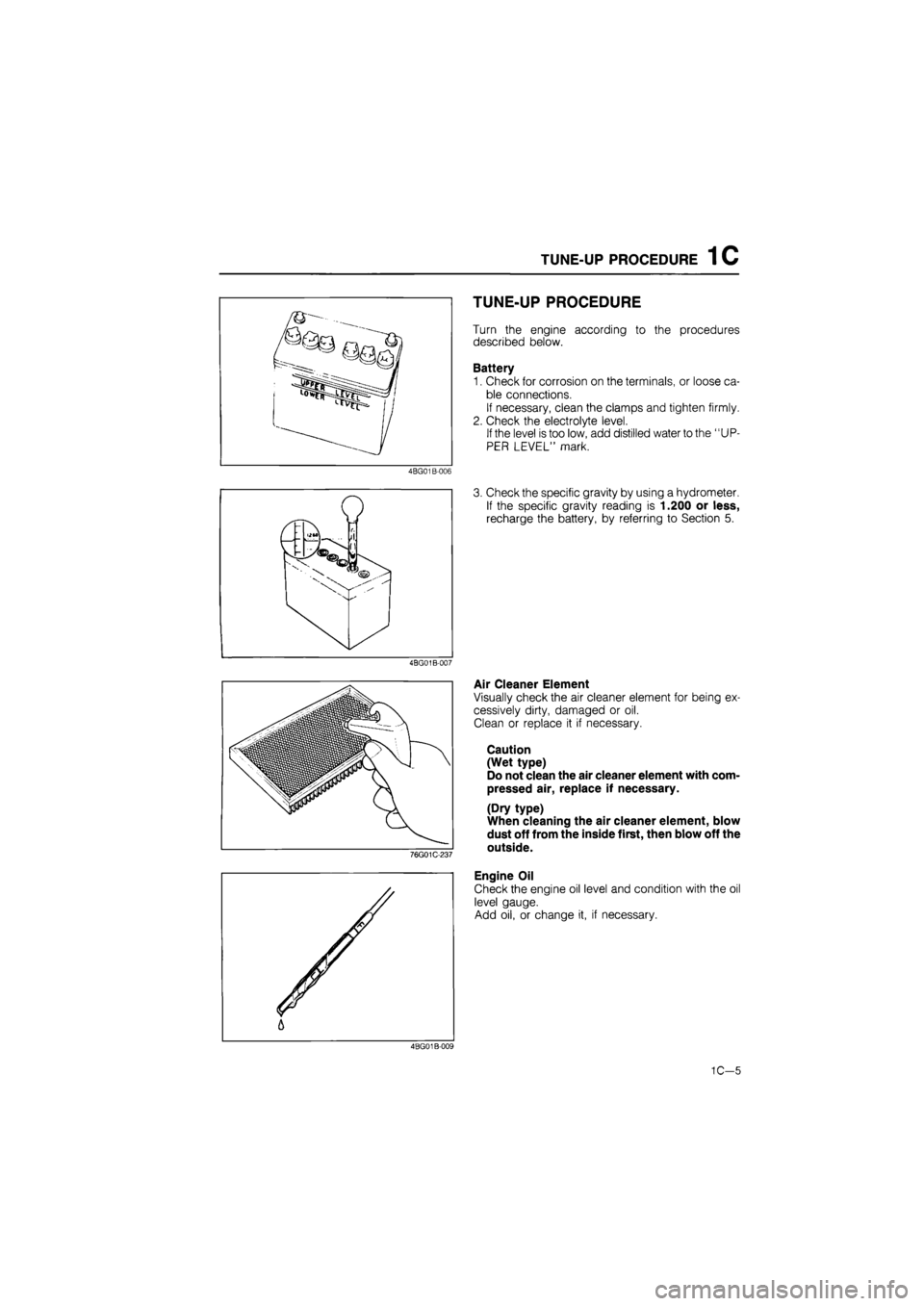
TUNE-UP PROCEDURE
Turn the engine according to the procedures
described below.
Battery
1. Check for corrosion on the terminals, or loose ca-
ble connections.
If necessary, clean the clamps and tighten firmly.
2. Check the electrolyte level.
If the level is too low, add distilled water to the "UP-
PER LEVEL" mark.
3. Check the specific gravity by using a hydrometer.
If the specific gravity reading is 1.200 or less,
recharge the battery, by referring to Section 5.
Air Cleaner Element
Visually check the air cleaner element for being ex-
cessively dirty, damaged or oil.
Clean or replace it if necessary.
Caution
(Wet type)
Do not clean the air cleaner element with com-
pressed air, replace if necessary.
(Dry type)
When cleaning the air cleaner element, blow
dust off from the inside first, then blow off the
outside.
Engine Oil
Check the engine oil level and condition with the oil
level gauge.
Add oil, or change it, if necessary.
4BG01B-009
1C—5
Page 218 of 1865
1C TUNE-UP PROCEDURE
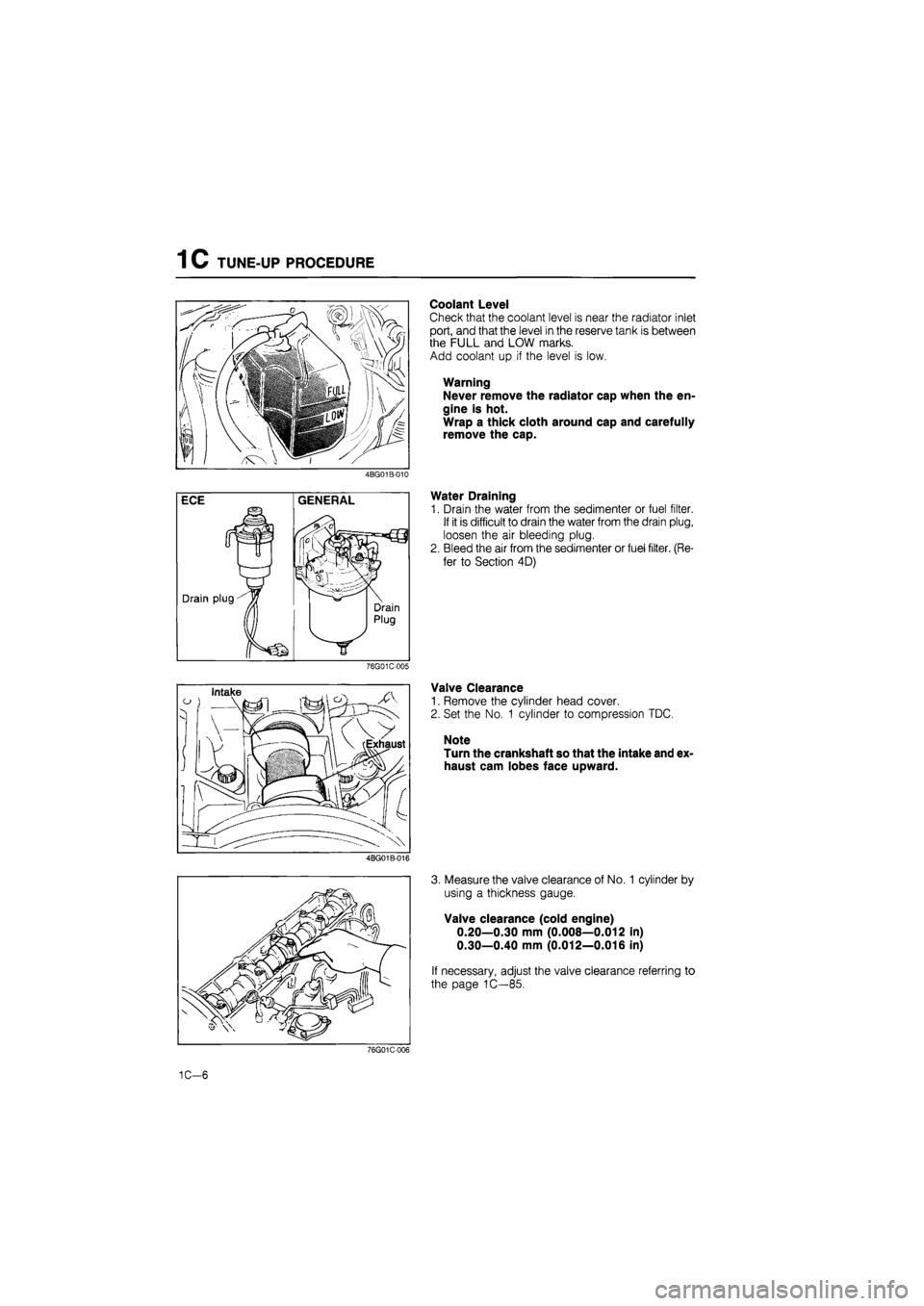
Coolant Level
Check that the coolant level is near the radiator inlet
port, and that the level in the reserve tank is between
the FULL and LOW marks.
Add coolant up if the level is low.
Warning
Never remove the radiator cap when the en-
gine is hot.
Wrap a thick cloth around cap and carefully
remove the cap.
4BG01B-010
Water Draining
1. Drain the water from the sedimenter or fuel filter.
If it is difficult to drain the water from the drain plug,
loosen the air bleeding plug.
2. Bleed the air from the sedimenter or fuel filter. (Re-
fer to Section 4D)
76G01C-005
Valve Clearance
1. Remove the cylinder head cover.
2. Set the No. 1 cylinder to compression TDC.
Note
Turn the crankshaft so that the intake and ex-
haust cam lobes face upward.
4BG01B-016
3. Measure the valve clearance of No. 1 cylinder by
using a thickness gauge.
Valve clearance (cold engine)
0.20—0.30 mm (0.008—0.012 in)
0.30—0.40 mm (0.012—0.016 in)
If necessary, adjust the valve clearance referring to
the page 1C—85.
76G01C-006
1C-6
Page 219 of 1865

TUNE-UP PROCEDURE 1C
P/S oil pump Checking point
B
Vacuum/^ i V pumpf o ) y ®
v Rear \ camshaft
J
pulley
A-—mP
P/S oil pump \ L^
76G01C-009
Drive Belt
1. Check the drive belt for wear, cracks, or fraying.
Replace if necessary.
2. Check the drive belt deflection by applying moder-
ate pressure (98 N, 10 kg, 22 lb) midway between
the pulleys.
Alternator
Deflection mm (in)
New 8.0-10.0 (0.31-0.39)
Used 9.0—11.0 (0.35—0.43)
If necessary, loosen the idler lock nut and adjust
the belt deflection by turning the adjust bolt.
Tightening torque:
37—52 N-m (3.8—5.3 m-kg, 27—38 ft-lb)
Vacuum pump and P/S oil pump
Deflection mm (in)
Vacuum
pump
New 7.5-8.5 (0.30-0.33) Vacuum
pump Used 8.5-9.5 (0 33-0.37)
P/S oil pump
New 6.5-7.5 (0.26-0 30) P/S oil pump Used 7.0-8.0 (0.28—0.31)
If necessary, adjust the belt deflection as follows.
(1) Loosen the vacuum pump bolts ©and (§).
(2) Lever the vacuum pump outward and apply
tension to the belt.
(3)Tighten the adjust bolt
Tightening torque:
19—26
N
m (1.9—2.6 m-kg, 14—19 ft-lb)
(4)Tighten the mounting bolt
Tightening torque:
37—52
N
m (3.8—5.3 m-kg, 27—38 ft-lb)
A/C compressor
Deflection mm (in)
New 8.5—9.5 (0.33—0.37)
Used 9.5-10.5 (0.37-0.41)
If necessary, loosen the idler lock nut and adjust
the belt deflection by turning the adjust bolt.
Tightening torque:
37—52 Nm (3.8—5.3 m-kg, 27—38 ft-lb)
1C-7
Page 220 of 1865

1C TUNE-UP PROCEDURE
Comprex supercharger
Deflection mm (in)
New 4 0-6.0 (0.16—0.23)
Used 8.0-10 0 (0 31-0.39)
If necessary, loosen the idler lock nut and adjust
the belt deflection by turning the adjust bolt.
Tightening torque:
16—23 Nm (1.6—2.3 m-kg, 12—17 ft-lb)
76G01C-011
o
INJECTION TIMING
1. Disconnect the negative battery cable.
2. Release the CSD using the screw driver.
3. Remove the cover on the clutch housing.
4. Turn the flywheel and set the indicator at ATDC.
5. Disconnect the injection pipes from the injection
pump.
76G04D-008
6. Remove the hydraulic head plug from the injec-
tion pump.
7. Mount the SST into the plug hole on the hydraulic
head so the tip of the dial gauge pointer touches
the plunger end of the pump and the dial gauge
indicates approx. 2.0 mm (0.08 in).
76G04D-009
8. Turn the crankshaft slowly counterclockwise to
30-50° BTDC.
9. Make sure the dial indicator pointer no longer
moves by slightly turning the crankshaft.
10. Set the dial gauge scale to Zero at the pointer.
76G04D-010
1C-8