MAZDA 626 1987 Workshop Manual
Manufacturer: MAZDA, Model Year: 1987, Model line: 626, Model: MAZDA 626 1987Pages: 1865, PDF Size: 94.35 MB
Page 171 of 1865
1 B INSPECTION AND REPAIR
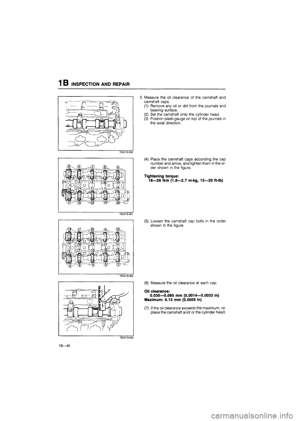
5. Measure the oil clearance of the camshaft and
camshaft caps.
(1) Remove any oil or dirt from the journals and
bearing surface.
(2) Set the camshaft onto the cylinder head.
(3) Position plasti-gauge on top of the journals in
the axial direction.
76G01B-060
(4) Place the camshaft caps according the cap
number and arrow, and tighten them in the or-
der shown in the figure.
Tightening torque:
18—26 N-m (1.8—2.7 m-kg, 13—20 ft-lb)
76G01B-061
(5) Loosen the camshaft cap bolts in the order
shown in the figure.
76G01B-062
(6) Measure the oil clearance at each cap.
Oil clearance:
0.035—0.085 mm (0.0014—0.0033 in)
Maximum: 0.15 mm (0.0059 in)
(7) If the oil clearance exceeds the maximum, re-
place the camshaft and/ or the cylinder head.
76G01B-063
1B—40
Page 172 of 1865
INSPECTION AND REPAIR 1 B
76G01B-125
76G01B-064
86U01X-100
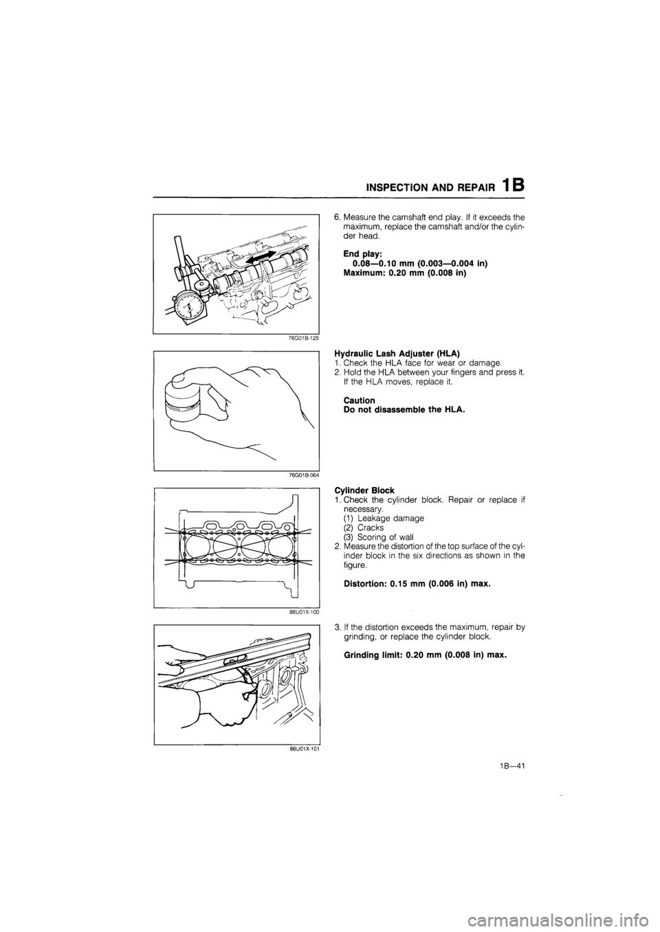
6. Measure the camshaft end play. If it exceeds the
maximum, replace the camshaft and/or the cylin-
der head.
End play:
0.08—0.10 mm (0.003—0.004 in)
Maximum: 0.20 mm (0.008 in)
Hydraulic Lash Adjuster (HLA)
1. Check the HLA face for wear or damage.
2. Hold the HLA between your fingers and press it.
If the HLA moves, replace it.
Caution
Do not disassemble the HLA.
Cylinder Block
1. Check the cylinder block. Repair or replace if
necessary.
(1) Leakage damage
(2) Cracks
(3) Scoring of wall
2. Measure the distortion of the top surface of the cyl-
inder block in the six directions as shown in the
figure.
Distortion: 0.15 mm (0.006 in) max.
3. If the distortion exceeds the maximum, repair by
grinding, or replace the cylinder block.
Grinding limit: 0.20 mm (0.008 in) max.
86U01X-101
1B—41
Page 173 of 1865
INSPECTION AND REPAIR 1 B
o ^ ^o
(7/T\V
-A-
B-
-c-
79G01C-070
1- B
79G01C-071
79G01C-072
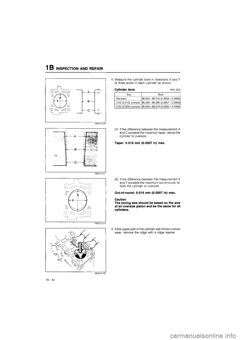
4. Measure the cylinder bore in directions X and Y
at three levels in each cylinder as shown.
Cylinder bore mm (in)
Size Bore
Standard 86.000-86.019 (3.3858-3.3866)
0.25 (0.010) oversize 86.250-86.269 (3.3957—3.3964)
0.50 (0.020) oversize 86.500—86.519 (3.4055-3.4062)
(1) If the difference between the measurement A
and C exceeds the maximum taper, rebore the
cylinder to oversize.
Taper: 0.019 mm (0.0007 in) max.
(2) If the difference between the measurement X
and Y exceeds the maximum out-of-round, re-
bore the cylinder to oversize.
Out-of-round: 0.019 mm (0.0007 in) max.
Caution
The boring size should be based on the size
of an oversize piston and be the same for all
cylinders.
5. If the upper part of the cylinder wall shows uneven
wear, remove the ridge with a ridge reamer.
86U01X-101
1B—42
Page 174 of 1865
INSPECTION AND REPAIR 1 B
Oil ring
groove
18mm IJUv. (0.709 in)*"! ^
79G01C-073
r Clearance
76G01A-130
69G01A-125
HV JT
101
^^Piston ring
vAv n^-n
iXXi ^^Piston ring ^^Piston ring
Piston
1. Inspect the outer circumferences of all pistons for
seizure or scoring. Replace if necessary.
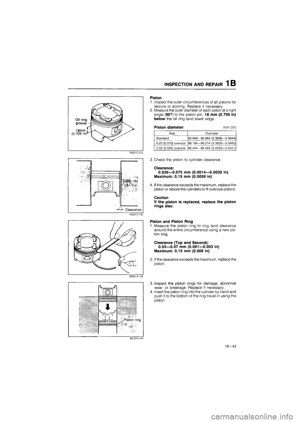
2. Measure the outer diameter of each piston at a right
angle (90°) to the piston pin, 18 mm (0.709 in)
below the oil ring land lower edge.
Piston diameter mm (in)
Size Diameter
Standard 85.944—85.964 (3.3836—3.3844)
0.25 (0.010) oversize 86.194-86.214 (3.3935-3.3942)
0.50 (0.020) oversize 86.444-86.464 (3.4033-3.4041)
3. Check the piston to cylinder clearance.
Clearance:
0.036—0.075 mm (0.0014—0.0030 in)
Maximum: 0.15 mm (0.0059 in)
4. If the clearance exceeds the maximum, replace the
piston or rebore the cylinders to fit oversize pistons.
Caution
If the piston is replaced, replace the piston
rings also.
Piston and Piston Ring
1. Measure the piston ring to ring land clearance
around the entire circumference using a new pis-
ton ring.
Clearance (Top and Second):
0.03—0.07 mm (0.001—0.003 in)
Maximum: 0.15 mm (0.006 in)
2. If the clearance exceeds the maximum, replace the
piston.
Inspect the piston rings for damage, abnormal
wear, or breakage. Replace if necessary.
Insert the piston ring into the cylinder by hand and
push it to the bottom of the ring travel in using the
piston.
86U01X-101
1B—43
Page 175 of 1865
1 B INSPECTION AND REPAIR
76G01B-065
%
-X
@H
C/ v M v M
76G01B-066
76G01B-067
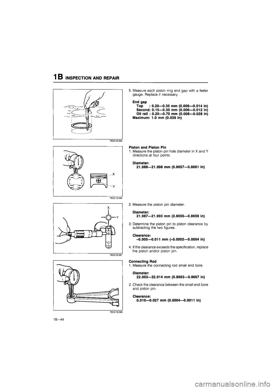
5. Measure each piston ring end gap with a feeler
gauge. Replace if necessary.
End gap
Top : 0.20—0.35 mm (0.008—0.014 in)
Second: 0.15—0.30 mm (0.006—0.012 in)
Oil rail : 0.20—0.70 mm (0.008—0.028 in)
Maximum: 1.0 mm (0.039 in)
Piston and Piston Pin
1. Measure the piston pin hole diameter in X and Y
directions at four points.
Diameter:
21.988—21.998 mm (0.8657—0.8661 in)
2. Measure the piston pin diameter.
Diameter:
21.987—21.993 mm (0.8656—0.8659 in)
3. Determine the piston pin to piston clearance by
subtracting the two figures.
Clearance:
-0.005—0.011 mm (-0.0002—0.0004 in)
4. If the clearance exceeds the specification, replace
the piston and/or piston pin.
Connecting Rod
1. Measure the connecting rod small end bore.
Diameter: 22.003—22.014 mm (0.8663—0.8667 in)
2. Check the clearance between the small end bore
and piston pin.
Clearance:
0.010—0.027 mm (0.0004—0.0011 in)
76G01B-063
1B—44
Page 176 of 1865
INSPECTION AND REPAIR 1 B
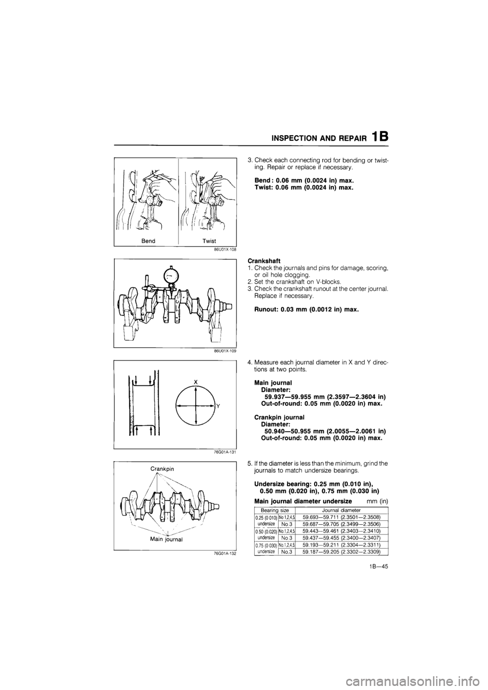
3. Check each connecting rod for bending or twist-
ing. Repair or replace if necessary.
Bend: 0.06 mm (0.0024 in) max.
Twist: 0.06 mm (0.0024 in) max.
86U01X-108
Crankshaft
1. Check the journals and pins for damage, scoring,
or oil hole clogging.
2. Set the crankshaft on V-blocks.
3. Check the crankshaft runout at the center journal.
Replace if necessary.
Runout: 0.03 mm (0.0012 in) max.
86U01X-109
4. Measure each journal diameter in X and Y direc-
tions at two points.
Main journal
Diameter:
59.937—59.955 mm (2.3597—2.3604 in)
Out-of-round: 0.05 mm (0.0020 in) max.
Crankpin journal
Diameter:
50.940—50.955 mm (2.0055—2.0061 in)
Out-of-round: 0.05 mm (0.0020 in) max.
76G01A-131
Crankpin
Main journal
5. If the diameter is less than the minimum, grind the
journals to match undersize bearings.
Undersize bearing: 0.25 mm (0.010 in),
0.50 mm (0.020 in), 0.75 mm (0.030 in)
Main journal diameter undersize mm (in)
69G01A-101
Bearing size Journal diameter
0.25
(0 010)
undersize
0.50 (0.020) undersize
No
1,2,4,5 59.693-59.711 (2.3501-2.3508) 0.25
(0 010)
undersize
0.50 (0.020) undersize
No 3 59.687-59.705 (2.3499-2.3506)
0.25
(0 010)
undersize
0.50 (0.020) undersize
No.1,2,4,5 59.443-59.461 (2.3403—2.3410)
0.25
(0 010)
undersize
0.50 (0.020) undersize No.3 59.437-59.455 (2.3400—2.3407)
0.75
(0 030)
undersize
NO.1,2,4,5 59.193-59.211 (2.3304-2.3311) 0.75
(0 030)
undersize No.3 59.187-59.205 (2.3302-2.3309)
1B—45
Page 177 of 1865
INSPECTION AND REPAIR 1 B
Rolled fillet
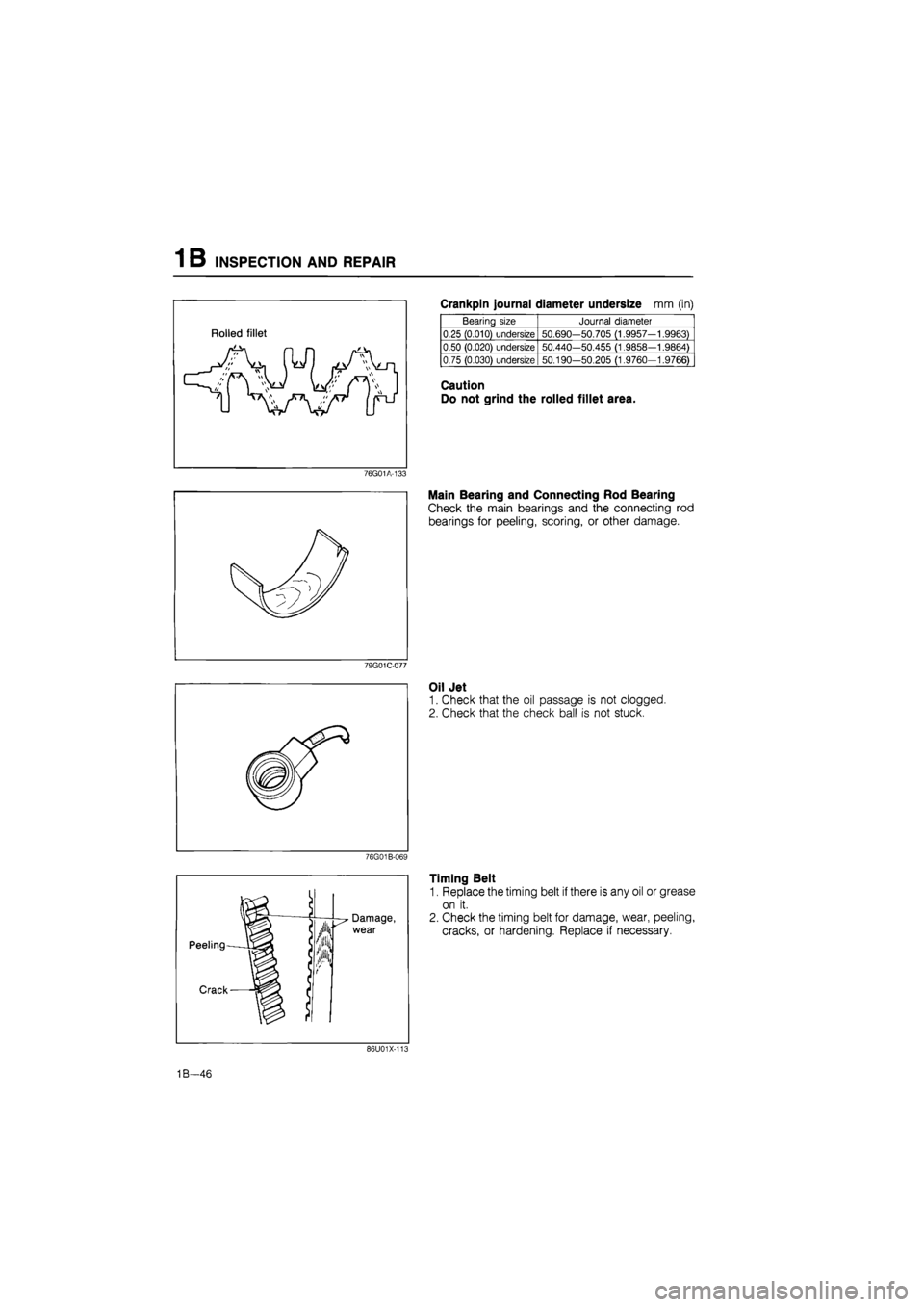
Crankpin journal diameter undersize mm (in)
Bearing size Journal diameter
0.25 (0.010) undersize 50.690-50.705 (1.9957—1.9963)
0.50 (0.020) undersize 50.440—50.455 (1.9858-1.9864)
0.75 (0.030) undersize 50.190-50.205 (1.9760-1.9766)
Caution
Do not grind the rolled fillet area.
76G01A-133
Main Bearing and Connecting Rod Bearing
Check the main bearings and the connecting rod
bearings for peeling, scoring, or other damage.
79G01C-077
Oil Jet
1. Check that the oil passage is not clogged.
2. Check that the check ball is not stuck.
76G01B-069
Timing Belt
1. Replace the timing belt if there is any oil or grease
on it.
2. Check the timing belt for damage, wear, peeling,
cracks, or hardening. Replace if necessary.
86U01X-101
1B—46
Page 178 of 1865
INSPECTION AND REPAIR 1 B
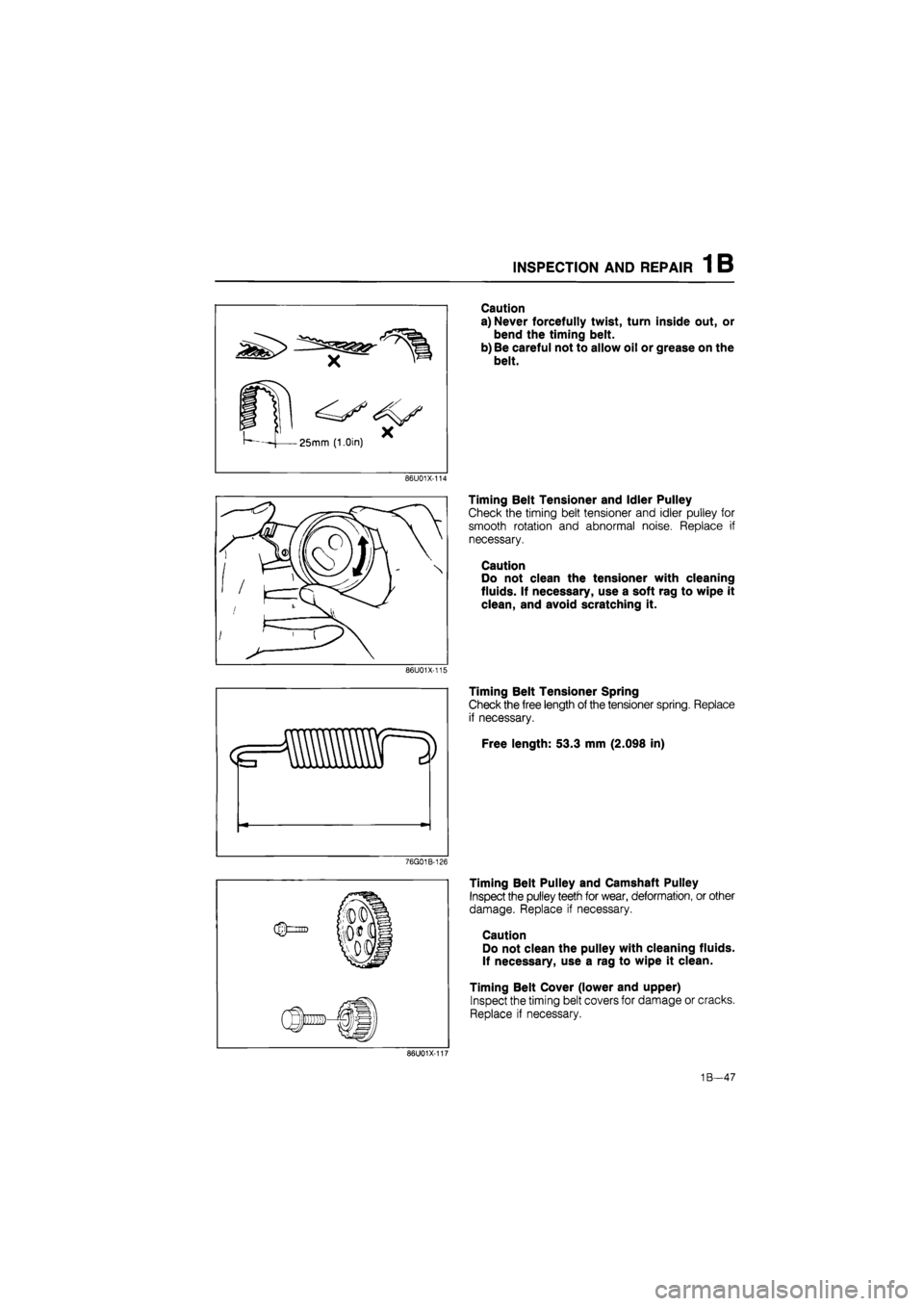
Caution
a) Never forcefully twist, turn inside out, or
bend the timing belt.
b) Be careful not to allow oil or grease on the
belt.
86U01X-114
Timing Belt Tensioner and Idler Pulley
Check the timing belt tensioner and idler pulley for
smooth rotation and abnormal noise. Replace if
necessary.
Caution
Do not clean the tensioner with cleaning
fluids. If necessary, use a soft rag to wipe it
clean, and avoid scratching it.
86U01X-115
Timing Belt Tensioner Spring
Check the free length of the tensioner spring. Replace
if necessary.
Free length: 53.3 mm (2.098 in)
76G01B-126
Timing Belt Pulley and Camshaft Pulley
Inspect the pulley teeth for wear, deformation, or other
damage. Replace if necessary.
Caution
Do not clean the pulley with cleaning fluids.
If necessary, use a rag to wipe it clean.
Timing Belt Cover (lower and upper)
Inspect the timing belt covers for damage or cracks.
Replace if necessary.
86U01X-101
1B—47
Page 179 of 1865
1 B ASSEMBLY (CYLINDER BLOCK)
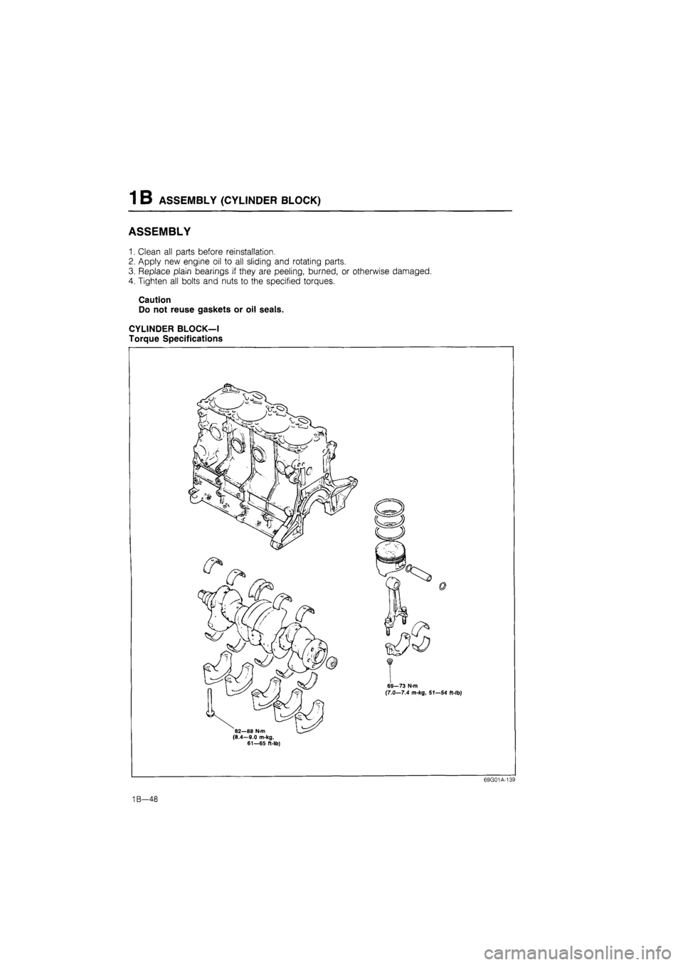
ASSEMBLY
1. Clean all parts before reinstallation.
2. Apply new engine oil to all sliding and rotating parts.
3. Replace plain bearings if they are peeling, burned, or otherwise damaged.
4. Tighten all bolts and nuts to the specified torques.
Caution
Do not reuse gaskets or oil seals.
CYLINDER BLOCK—I
Torque Specifications
69G01A-139
1B—48
Page 180 of 1865
ASSEMBLY (CYLINDER BLOCK) 1 B
76G01B-070
76G01B-071
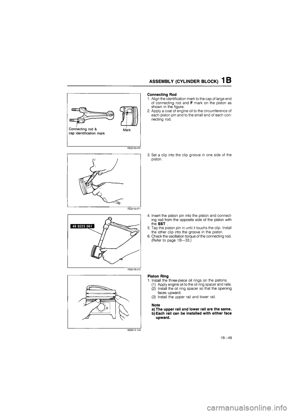
Connecting Rod
1. Align the identification mark to the cap of large end
of connecting rod and F mark on the piston as
shown in the figure.
2. Apply a coat of engine oil to the circumference of
each piston pin and to the small end of each con-
necting rod.
3. Set a clip into the clip groove in one side of the
piston.
4. Insert the piston pin into the piston and connect-
ing rod from the opposite side of the piston with
the SST .
5. Tap the piston pin in until it touchs the clip. Install
the other clip into the groove in the piston.
6. Check the oscillation torque of the connecting rod.
(Refer to page 1B—33.)
Piston Ring
1. Install the three-piece oil rings on the pistons.
(1) Apply engine oil to the oil ring spacer and rails.
(2) Install the oil ring spacer so that the opening
faces upward.
(3) Install the upper rail and lower rail.
Note
a) The upper rail and lower rail are the same.
b)Each rail can be installed with either face
upward.
69G01A-144
1B—49