ignition MAZDA PROTEGE 1992 Owner's Guide
[x] Cancel search | Manufacturer: MAZDA, Model Year: 1992, Model line: PROTEGE, Model: MAZDA PROTEGE 1992Pages: 1164, PDF Size: 81.9 MB
Page 283 of 1164

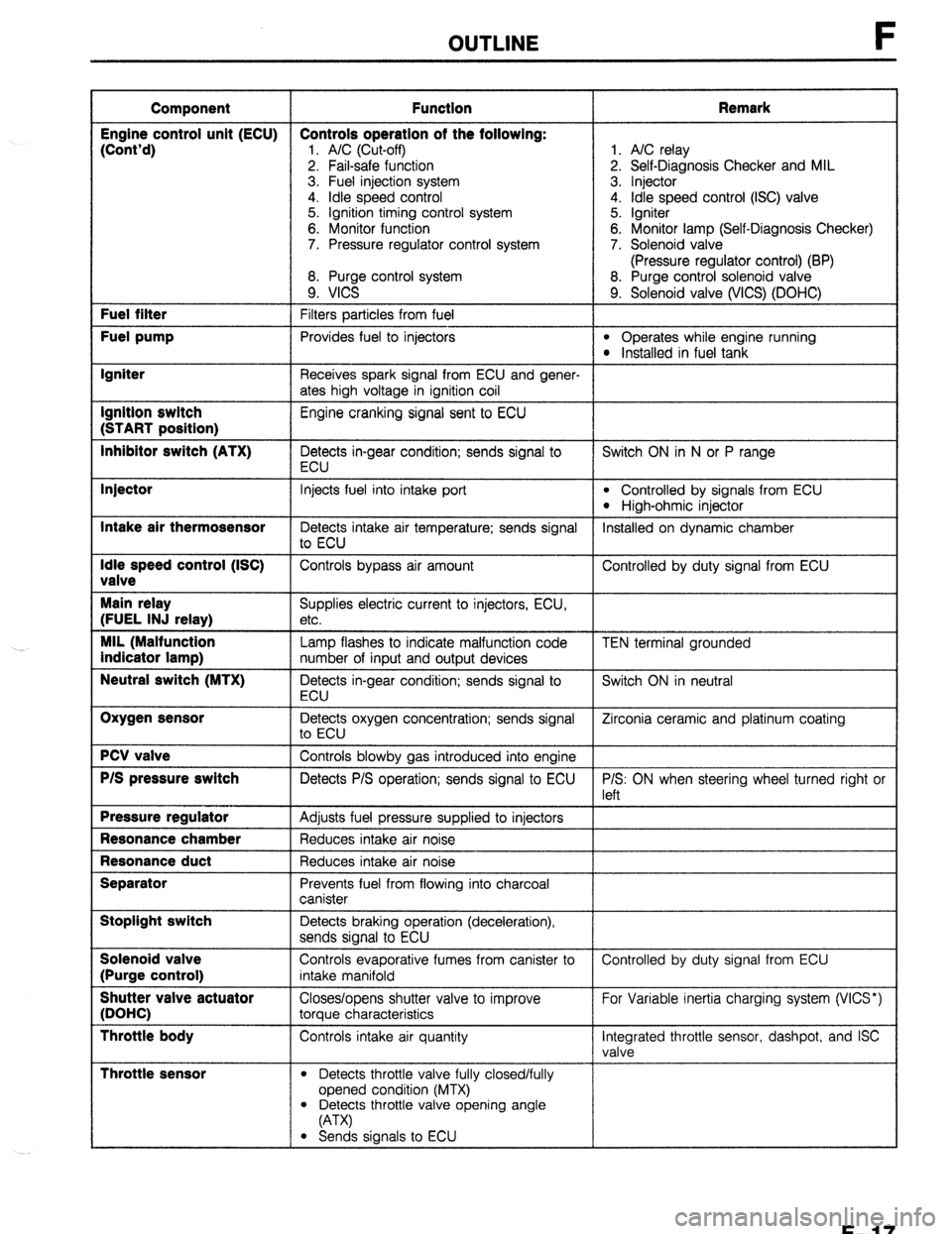
OUTLINE
Component Function Remark
Engine control unit (ECU) Controls operation of the following:
(Cont’d)
1. A/C (Cut-off) 1. A/C relay
2. Fail-safe function 2. Self-Diagnosis Checker and MIL
3. Fuel injection system 3. Injector
4. idle speed control 4. Idle speed control (ISC) valve
5. Ignition timing control system 5. Igniter
6. Monitor function 6. Monitor lamp (Self-Diagnosis Checker)
7. Pressure regulator control system 7. Solenoid valve
(Pressure regulator control) (BP)
8. Purge control system 8. Purge control solenoid valve
9. VICS 9. Solenoid valve (WCS) (DOHC) Fuel filter
Filters particles from fuel Fuel pump
Provides fuel to injectors l Operates while engine running l Installed in fuel tank Igniter
Receives spark signal from ECU and gener-
ates high voltage in ignition coil Ignition switch
Engine cranking signal sent to ECU (START position)
Inhibitor switch (ATX)
Detects in-gear condition; sends signal to Switch ON in N or P range
ECU Injector
Intake air thermosensor
Idle speed control (ISC)
valve
Main relay
(FUEL INJ relay)
MIL (Malfunction
indicator lamp)
Neutral switch (MTX)
Oxygen sensor
PCV valve
P/S pressure switch
Pressure regulator
Resonance chamber
Resonance duct
Separator
Stoplight switch
Solenoid valve
(Purge control)
Shutter valve actuator
(DOHC)
Throttle body
Throttle sensor
Injects fuel into intake port l Controlled by signals from ECU
l High-ohmic injector
Detects intake air temperature; sends signal Installed on dynamic chamber
to ECU
Controls bypass air amount Controlled by duty signal from ECU
Supplies electric current to injectors, ECU,
etc.
Lamp flashes to indicate malfunction code
number of input and output devices
Detects in-gear condition; sends signal to
ECU
Detects oxygen concentration; sends signal
to ECU
Controls blowby gas introduced into engine
Detects P/S operation; sends signal to ECU
Adjusts fuel pressure supplied to injectors
Reduces intake air noise
Reduces intake air noise
Prevents fuel from flowing into charcoal
canister
Detects braking operation (deceleration),
sends signal to ECU
Controls evaporative fumes from canister to
intake manifold
Closes/opens shutter valve to improve
torque characteristics
Controls intake air quantity
l Detects throttle valve fully closed/fully
opened condition (MTX) TEN terminal grounded
Switch ON in neutral
Zirconia ceramic and platinum coating
P/S: ON when steering wheel turned right or
left
Controlled by duty signal from ECU
For Variable inertia charging system (VICS*)
Integrated throttle sensor, dashpot, and ISC
valve
l Detects throttle valve opening angle
(A-W
l Sends signals to ECU
F-l 7
Page 287 of 1164
![MAZDA PROTEGE 1992 Owners Guide TROUBLESHOOTING GUIDE F
r
- SENSORS
z-----
‘RES-
‘URE
‘WITCH FRL (Dsy
ime Run-
ling
.ight)
:ONTROL
INIT
CANADA]
)FF
3attery
oltage)
T- IEUTRAL
rND
:LUTCH
iWITCHES
MTX) IIAGNO MAZDA PROTEGE 1992 Owners Guide TROUBLESHOOTING GUIDE F
r
- SENSORS
z-----
‘RES-
‘URE
‘WITCH FRL (Dsy
ime Run-
ling
.ight)
:ONTROL
INIT
CANADA]
)FF
3attery
oltage)
T- IEUTRAL
rND
:LUTCH
iWITCHES
MTX) IIAGNO](/img/28/57077/w960_57077-286.png)
TROUBLESHOOTING GUIDE F
r
- SENSORS
z-----
‘RES-
‘URE
‘WITCH FRL (Dsy
ime Run-
ling
.ight)
:ONTROL
INIT
CANADA]
)FF
3attery
oltage)
T- IEUTRAL
rND
:LUTCH
iWITCHES
MTX) IIAGNOSIS
:ONNEC-
‘OR TEN
‘ERMINAL
rEST
‘ERMINAL) IGNITION SWITCH
s kgnal has
r IO effect
C In ECU
I neutral:
.ow volt-
rge signal
II ECU
w
-
f
I
Iriving in
iny gear:
iigh volt-
ige signal
o ECU
Battery TOP-
IGHT
WITCH UHIBITOR
iWITCH
4TX) L/C
;WITCH
5
IL
IGNAL
Sl ignal has
nl 3 effect
01 n ECU
H
0
F-f
S
C
VI
si
E
te
VI
C
VI
si
i
1 T
eadlight
r rear
‘indow
efroster
Nitch
IN: High
pltage
gnal to
CU (Bat-
try
sltage)
IFF: Low
altage
gnal to
cu
3elow
.5V)
B
S'
0
C,
C
L
E
E
II
(
\i
c
E
t’
I lower
Nitch**
r Electri-
al fan
IN: Low
foltage
signal to
iCU (Be-
3w 1.W)
IFF: High
loltage
rignal to
ICU (Bat-
ev
voltage)
I
OFF ITART
‘OSITION IN
OSITION
‘ends sig
al to
CU (Bat-
?ry
oltage) #ignal has
0 effect
#n ECU ignal has
0 effect
n ECU ignal has
0 effect
n ECU ;ignal has
IO effect
rn ECU ignal has
0 effect
n ECU
rake pedal Ggnal has
IQ effect
In ECU
1NorP
ange: No
ignal to
.cu
w
-
7D
ange: No
#ignal to
.cu
Battery
foltage)
- - - - -
ends sig-
31 to ECU
jattr ?ry
Atac
-2
/heel -
Jrned:
ow volt-
ge signal
I ECU
3elow
.5V)
teering
/heel
traight
head:
ligh volt-
ge signal
) ECU
dattery .erminal
lot
Irounded:
iigh volt-
tge Signal
3 ECU
Battery
roltage)
‘erminal
Irounded:
.ow volt-
rge signal
3 ECU
Below lo signal
ent to
cu
3elow
5V) r/C switch
IN:
iends sig-
ial to
CU (Be-
IW 1.5V)
r/C switch
IFF: No
ignal to
CU (Bat-
3ry
‘oltage) )RL ON:
w ends sig-
al to
CU (Bat-
2ry
oltage) lo signal
3 ECU
3elow
.5V) )RL OFF:
3attery
oltage)
I .5V’
medal
Sends
signal to
KU
Battery
voltage)
- -
In N or P
range:
Sends sig-
nal to ECU
PV In neutral:
Low volt-
age stgnal
to ECU
(W
I -
- - -
OFF OFF OFF OFF OFF OFF OFF
OFF OFF
23UOFX-0’
+’ Blower switch: 2nd position or more
F-21
Page 288 of 1164

F TROUBLESHOOTING GUIDE
Output Devices and Engine Conditions
Note
. The data in this chart is for reference only.
INJECTOR
CONDITIONS
CRANKING
-COLD ENGINE
l COLD AIR l COLD COOLANT
COLD START
-FAST IDLE
l COLD AIR l COLD COOLANT
COLD DRIVEAWAY
-PART THROTTLE
l COLD AIR l COLD COOLANT
WARM DRIVEAWAY
-PART THROTTLE
. WARM AIR
l WARM COOLANT
HOT CRUISE
l WARM AIR l WARM COOLANT Zero
One
mrnute
Two
minutes
Three
minutes
I AIR
INJECTION “AL”E
INJECTION TlMlNG
A
All A
cylinders
each
ignition
pulse
1
Rich Open:
coolant
tem-
perature:
Below
40%
(104OF)
,
I/
Rich and
2-group” 1’
lean l-group” /I
,
i
HOT ACCELERATION
-60% THROTTLE
-lOT ACCELERATION
-WIDE OPEN
THROTTLE
Closed ISC
VALVE
1, THREE-WAY
SOLENOID SOLENOID
VALVE VALVE
(PURGE
(PRESSURE
CONTROL) REGULATOR
CONTROL)‘3
c
OFF
(Purge
cut)
Large
1
, AK
RELAY
amount or
bypass air
OFF
(Vacuum
to
pressure
regulator)
After start-
rng: ON dur-
ing hot start
only (Vacu-
um cut)
OFF
l 2 SOHC, *’ BP
F-22
Page 290 of 1164

F TROUBLESHOOTING GUIDE
RELATIONSHIP CHART
OUTPUT DEVICE
INPUT DEVICE
DIAGNOSIS CONNECTOR
[TEN TERMINAL) 0 0 0 0
IGNITION SWITCH (START POSITION) 0 0 0 0 0 0
E/L SIGNALg4 0
0
P/S PRESSURE SWITCH 0 0
B/C SWITCH 0 0 0
INHIBITOR SWITCH (ATX) 0 0 0 0 0 0 0
NEUTRALANDCLUTCH
SWITCHES (MTX) 0 0 0 0 0 0 0
STOPLIGHT SWITCH 0
0
&TMOSPHERIC PRESSURE SENSOR
[IN ECU) o 0 0 0 0
rHROTTLE SENSOR 0 0 0 0 0 0 0
INTAKE AIR THERMOSENSOR 0 0 0 0 0
MRFLOW METER 0 0 0 0 0
3XYGEN SENSOR 0 0 0 0
JVATERTHERMOSENSOR 0 0 0 0 0 0 0
G-SIGNAL*’ 0 0
3ISTRIBUTOR
Ne-SIGNAL 0 0 0 0 0 0 0 0
-- ,.-, ,--., ,.*
+z
*3 &HC
MIL: Malfunction Indicator Lamp
r.9u”rn-” I
*’ E/L SIGNAL: Blower fan control switch second position or higher, cooling fan operating, headlights ON, or rear win-
dow defroster switch ON
F-24
Page 292 of 1164

F TROUBLESHOOTING GUIDE
Troubleshooting chart
6 I
CRANKS NORMALLY BUT HARD TO START - WHEN ENGINE COLD
*Engine cranks at normal speed but requires excessive crankmg time before starting
IESCRIP-
l Batterv in normal condition
llON l Restans OK after warmup l Engine runs normally at idle [If Idle condrtron is not OK, refer to “Rough idle” (Nos. S-12)]
TROUBLESHOOTING HINTS]
B Air/Fuel mrxture too rrch @Air/Fuel mixture too lean
l Arrflow meter stickrng l Fuel iniectron control malfunction
l Aw cleaner element clogged
*Idle weed control malfunction (Correction for coolant temperature)
0 Poor atomizatron
- ~~ ~~ *Low RVP (summer) fuel is used rn cold weather >
f INSPECTION T Check If “00” is displayed on Self-Diagnosis
Checker wth Ignition switch ON -
Yes
No CT page F-73
SYSTEM SELECT: 1
“SELECT SW: A
Check if ECU terminal voltages are OK
(Especially 1C. 2D. and 2Q)
cc page F-144
Check If engine starts easily when throttle valve -
Yes
-
NO
-
Yes ACTION
Go to next step
Malfunctlon Code No. dlsplayed
Check for cause (Refer to specified
check sequence)
“58” flashes CT- page F-79
Check ECU terminal 1F voltage
Speciflcetlon: Battery voltage CT page F-144
(Ignition ewltch ON)
+ If OK, replace ECU CT page F-143
e If. not OK, check wrring between
ECU and Self-Diagnoos Checker
Go to next step
Check for cause CI page F-145
(-!hnrlr ,‘ ICP ..-I..- .^ nv
c+ page F-103
13UOFX-009
DESCRIPTION:
Further describes the symptom. Confirm that the chart addresses the actual symptom before beginning
troubleshooting.
TROUBLESHOOTING HINTS:
This describes the possible point of malfunction.
STEP:
This shows the order of troubleshooting. Proceed with troubleshooting as indicated.
INSPECTION:
This describes an inspection to quickly determine the malfunction of parts. If a detailed procedure is necessary
to perform the INSPECTION, refer to the page shown by the “~7” mark.
ACTION:
This recommends the appropriate action to take as a result (Yes/No) of the INSPECTION. How to perform
the action is described on the reference page shown by the “~7” mark.
OWOFX-016
F-26
Page 295 of 1164

TROUBLESHOOTING GUIDE F
REAR SEAT C
03UOFX-01
9MUOF2-1;
PRECAUTION
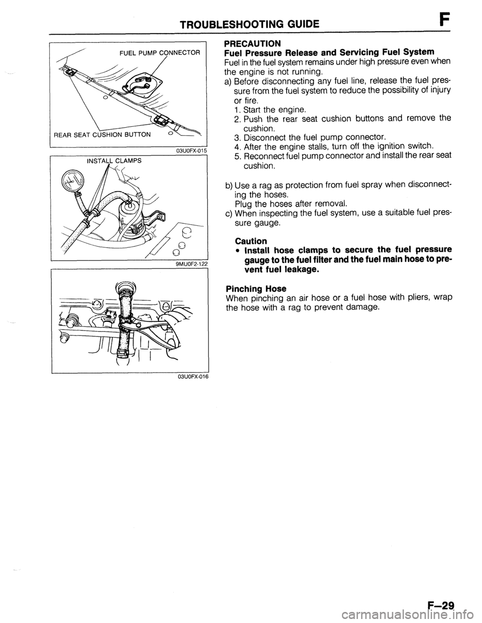
Fuel Pressure Release and Servicing Fuel System
Fuel in the fuel system remains under high pressure even when
the engine is not running.
a) Before disconnecting any fuel line, release the fuel pres-
sure from the fuel system to reduce the possibility of injury
or fire.
1. Start the engine.
2. Push the rear seat cushion buttons and remove the
cushion.
3. Disconnect the fuel pump connector.
4. After the engine stalls, turn off the ignition switch.
5. Reconnect fuel pump connector and install the rear seat
cushion.
b) Use a rag as protection from fuel spray when disconnect-
ing the hoses.
Plug the hoses after removal.
c) When inspecting the fuel system, use a suitable fuel pres-
sure gauge.
Caution
l Install hose clamps to secure the fuel pressure
gauge to the fuel filter and the fuel main hose to pre-
vent fuel leakage.
Pinching Hose
When pinching an air hose or a fuel hose with pliers, wrap
the hose with a rag to prevent damage.
03UOFX-016
F-29
Page 296 of 1164

F TROUBLESHOOTING GUIDE
SYMPTOM TROUBLESHOOTING
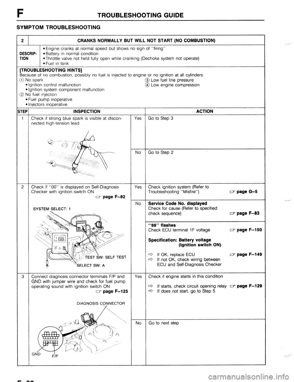
2 CRANKS NORMALLY BUT WILL NOT START (NO COMBUSTION)
l Engine cranks at normal speed but shows no sign of “firing”
DESCRIP-
*Battery in normal condition
TION
*Throttle valve not held fully open while cranking (Dechoke system not operate)
*Fuel in tank [TROUBLESHOOTING HINTS]
Because of no combustion, possibly no fuel is injected to engine or no ignition at all cylinders
:I) No spark
@I Low fuel line pressure
l Ignition control malfunction
@ Low engine compression l Ignition system component malfunction
3 No fuel injection
l Fuel pump inoperative l Injectors inoperative
TEP INSPECTION
ACTION
1 Check if strong blue spark is visible at discon-
Yes Go to Step 3
netted high-tension lead
No Go to Step 2
2 Check if “00” is displayed on Self-Diagnosis
Yes Check ignition system (Refer to
Checker with ignition switch ON
Troubleshooting “Misfire”) w page G-5
w page F-82
No Service Code No. displayed
Check for cause (Refer to specified
check sequence) w page F-83
“88” flashes
Check ECU terminal 1F voltage w page F-150
Specification: Battery voltage
(Ignition switch ON)
W: SELF TEST e If OK, replace ECU w page F-149 c3 If not OK, check wiring between
SELECT SW: A ECU and Self-Diagnosis Checker
3 Connect diagnosis connector terminals F/P and
Yes Check if engine starts in this condition
GND with jumper wire and check for fuel pump
operating sound with ignition switch ON c3 If starts, check circuit opening relay c7 page F-129
w page F-125
c3 If does not start, go to Step 5
DIAGNOSIS C
Go to next step ._-,
._. ,
F-30
Page 297 of 1164

TROUBLESHOOTING GUIDE F
w page F-125
tor (W/R) wire with ignition switch ON
MTX...lN, 2A, 2U, 2V
ATX... IT, 3A, 3U, 3V w page F-150
w page F-172
Fuel Line pressure:
265-314 kPa (2.7-3.2 kg/cm2, 36-46 psi)
fuel return hose w page F-129
fuel return hose is clogged or w page F-120
CT page F-130
(6.5 kg/cm2, 121 psi)-300 rpm
(9.0 kg/cm2, 128 psi)300 rpm
l Defective cylinder head gasket l Distorted cylinder head
WEAR AND C
AMAGE AND
ETERIORATION CT- page F-149
F-31
Page 298 of 1164

F TROUBLESHOOTING GUIDE
3 CRANKS NORMALLY BUT WILL NOT START (PARTIAL COMBUSTION) - WHEN ENGINE COLD
DESCRIP- *Engine cranks at normal speed but shows only partial combustion and will not continue to run
TION
l Battery in normal condition
*Fuel in tank
[TROUBLESHOOTING HINTS]
0 Air/Fuel mixture too rich
*Air cleaner element clogged
l Airflow meter stuck @ Low engine compression
@ Air/Fuel mixture too lean
l Fuel injection control malfunction
(Correction for coolant temperature)
*Low fuel line pressure
*Air leakage of intake air system
Checker with ignition switch ON
CT page F-83
w page F-150
Specification: Battery voltage
(Ignition switch ON)
W: SELF TEST w page F-149
Fuel line pressure:
285-314 kPa (2.7-3.2 kg/cm’, 38-48 psi) If fuel line pressure quickly in-
creases, check pressure regulator CF- page F-129
d If fuel line pressure gradually in-
creases check for clogging be-
I pump and pressure
Check if fuel return hose is clogged or
F-32
Page 301 of 1164

TROUBLESHOOTING GUIDE F
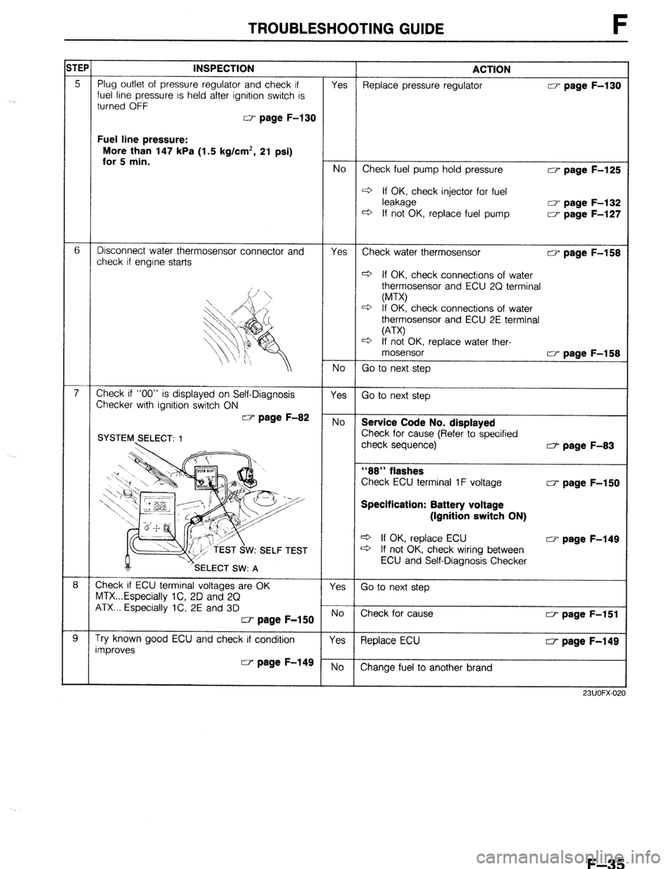
TEPt INSPECTION ACTION
Fuel line pressure:
More than 147 kPa (1.5 kg/cm*, 21 psi)
w page F-125
4 If OK, check injector for fuel
w page F-132
w page F-127
w page F-158
+ If OK check connections of water
osensor and ECU 2Q terminal
check connections of water
osensor and ECU 2E terminal
K, replace water ther-
w page F-83
w page F-150
Specification: Battery voltage
(Ignition switch ON)
Q If OK, replace ECU CT page F-149
+ If not OK, check wiring between
ECU and Self-Diagnosis Checker
23UOFX-0:
F-35