ignition MAZDA PROTEGE 1992 Manual Online
[x] Cancel search | Manufacturer: MAZDA, Model Year: 1992, Model line: PROTEGE, Model: MAZDA PROTEGE 1992Pages: 1164, PDF Size: 81.9 MB
Page 387 of 1164
FUEL PUMP CONNECTOR
/
REAR SEAT C
FUEL SYSTEM F
PRECAUTION
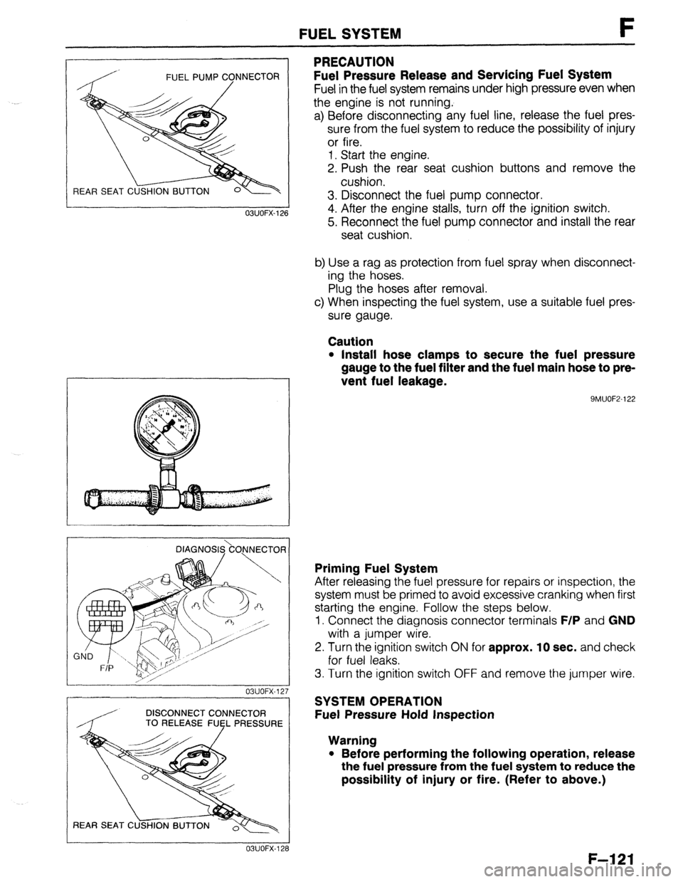
Fuel Pressure Release and Servicing Fuel System
Fuel in the fuel system remains under high pressure even when
the engine is not running.
a) Before disconnecting any fuel line, release the fuel pres-
sure from the fuel system to reduce the possibility of injury
or fire.
1. Start the engine.
2. Push the rear seat cushion buttons and remove the
cushion.
3. Disconnect the fuel pump connector.
4. After the engine stalls, turn off the ignition switch.
5. Reconnect the fuel pump connector and install the rear
seat cushion.
b) Use a rag as protection from fuel spray when disconnect-
ing the hoses.
Plug the hoses after removal.
c) When inspecting the fuel system, use a suitable fuel pres-
sure gauge.
Caution
l Install hose clamps to secure the fuel pressure
gauge to the fuel filter and the fuel main hose to pre-
vent fuel leakage.
9MUOF2-122 OBUOFX-126
DlAGNOS&O,NNECTOR
03UOFX-12.
-
DISCONNECT CONNECTOR
/ TO RELEASE FUEL PRESSURE
03UOFX-12;
Priming Fuel System
After releasing the fuel pressure for repairs or inspection, the
system must be primed to avoid excessive cranking when first
starting the engine. Follow the steps below.
1. Connect the diagnosis connector terminals
F/P and GND
with a jumper wire.
2. Turn the ignition switch
ON for approx. 10 sec. and check
for fuel leaks.
3. Turn the ignition switch OFF and remove the jumper wire.
SYSTEM OPERATION
Fuel Pressure Hold Inspection
Warning
l Before performing the following operation, release
the fuel pressure from the fuel system to reduce the
possibility of injury or fire. (Refer to above.)
F-121
Page 388 of 1164
F FUEL SYSTEM
OSUOFX-129
DIAGNOSIS.\CO.NNECTOR j
/, I 23UOFX-104
DISCONNECT CONNECTOR
TO RELEASE FlJsL PRESSURE
L 23UOFX-105
INSTALL CLAMPS
DIAGNOSI$kO)lNECTOfl
I
23UOFX-ll
F-l 22
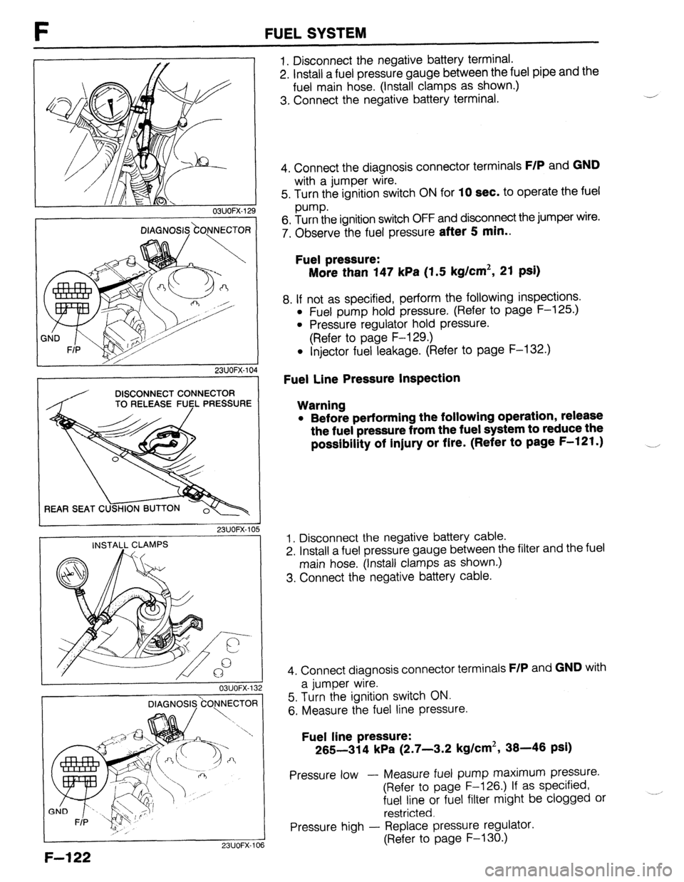
1. Disconnect the negative battery terminal.
2. Install a fuel pressure gauge between the fuel pipe and the
fuel main hose. (Install clamps as shown.)
3. Connect the negative battery terminal. J
4. Connect the diagnosis connector terminals
F/P and GND
with a jumper wire.
5. Turn the ignition switch ON for
10 sec. to operate the fuel
pump.
6. Turn the ignition switch OFF and disconnect the jumper wire.
7. Observe the fuel pressure
after 5 min..
Fuel pressure:
More than 147 kPa (1.5 kg/cm2, 21 psi)
8. If not as specified, perform the following inspections.
l Fuel pump hold pressure. (Refer to page F-125.)
l Pressure regulator hold pressure.
(Refer to page F-129.)
l Injector fuel leakage. (Refer to page F-132.)
Fuel Line Pressure Inspection
Warning
l Before performing the following operation, release
the fuel pressure from the fuel system to reduce the
possibility of injury or fire. (Refer to page F-121.) __,
1. Disconnect the negative battery cable.
2. Install a fuel pressure gauge between the filter and the fuel
main hose. (Install clamps as shown.)
3. Connect the negative battery cable.
4. Connect diagnosis connector terminals
F/P and GND with
a jumper wire.
5. Turn the ignition switch ON.
6. Measure the fuel line pressure.
Fuel line pressure:
265-314 kPa (2.7-3.2 kg/cm2, 38-46 psi)
Pressure low - Measure fuel pump maximum pressure.
(Refer to page F-126.) If as specified,
fuel line or fuel filter might be clogged or
restricted.
Pressure high - Replace pressure regulator.
(Refer to page F-130.)
Page 391 of 1164
FUEL SYSTEM F
DIAGNOSI&ONNECTOR
03UOFX-138
I I 23UOFX-110
,
DISCONNECT CONNECTOR
REAR SEAT C
23UOFX-11
03UOFX-11
OBUOFX-11
FUEL PUMP
Inspection
Fuel pump operation
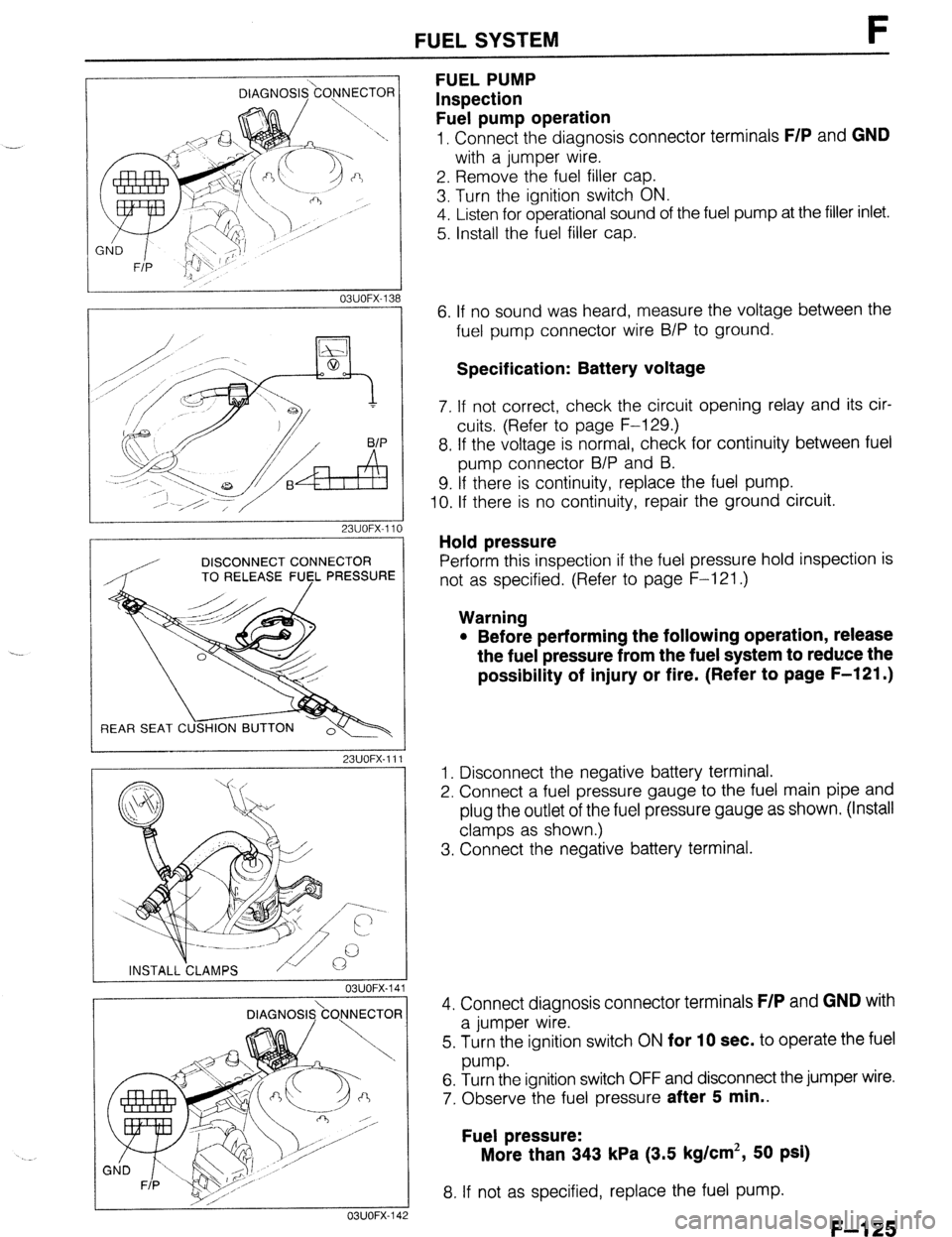
1, Connect the diagnosis connector terminals F/P and GND
with a jumper wire.
2. Remove the fuel filler cap.
3. Turn the ignition switch ON.
4. Listen for operational sound of the fuel pump at the filler inlet.
5. Install the fuel filler cap.
6. If no sound was heard, measure the voltage between the
fuel pump connector wire B/P to ground.
Specification: Battery voltage
7. If not correct, check the circuit opening relay and its cir-
cuits (Refer to page F-129.)
8. If the voltage is normal, check for continuity between fuel
pump connector B/P and B.
9. If there is continuity, replace the fuel pump.
IO. If there is no continuity, repair the ground circuit.
Hold pressure
Perform this inspection if the fuel pressure hold inspection is
not as specified. (Refer to page F-121 .)
Warning
l Before performing the following operation, release
the fuel pressure from the fuel system to reduce the
possibility of injury or fire. (Refer to page F-121 .)
1. Disconnect the negative battery terminal.
2. Connect a fuel pressure gauge to the fuel main pipe and
plug the outlet of the fuel pressure gauge as shown. (Install
clamps as shown.)
3. Connect the negative battery terminal.
4. Connect diagnosis connector terminals
F/P and GND with
a jumper wire.
5. Turn the ignition switch ON
for 10 sec. to operate the fuel
w-w.
6. Turn the ignition switch OFF and disconnect the jumper wire.
7. Observe the fuel pressure
after 5 min..
Fuel pressure:
More than 343 kPa (3.5 kg/cm’, 50 psi)
8. If not as specified, replace the fuel pump.
F-l 25
Page 392 of 1164
FUEL SYSTEM
Fuel pump maximum pressure
DISCONNECT CONNECTOR
TO RELEASE FUCL PRESSURE
Warning
23UOFX-11
OBUOFX-144 l
Before performing the following operation, release
the fuel pressure from the fuel system to reduce the
possibility of injury or fire. (Refer to page F-121 .) 4
1
2
23UOFX-15 7
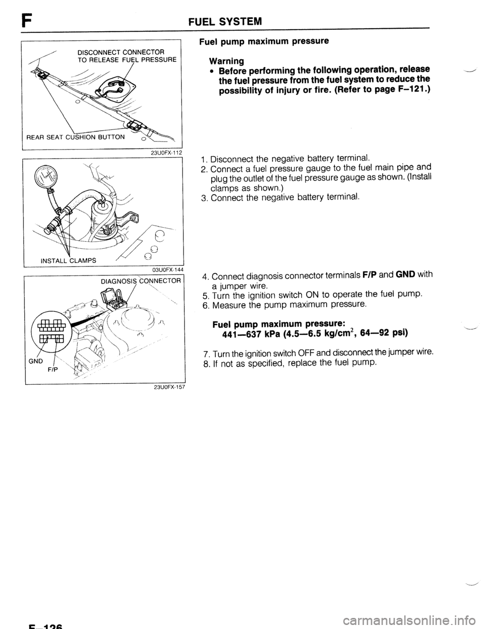
1. Disconnect the negative battery terminal.
2. Connect a fuel pressure gauge to the fuel main pipe and
plug the outlet of the fuel pressure gauge as shown. (Install
clamps as shown.)
3. Connect the negative battery terminal.
4. Connect diagnosis connector terminals
F/P and GND with
a jumper wire.
5. Turn the ignition switch ON to operate the fuel pump.
6. Measure the pump maximum pressure.
Fuel pump maximum pressure:
441-637 kPa (4.5-6.5 kg/cm2, 64-92 psi) .--
7. Turn the ignition switch OFF and disconnect the jumper wire.
8. If not as specified, replace the fuel pump.
F-l 26
Page 396 of 1164
F FUELSYSTEM
DISCONNECT CONNECTOR
TO RELEASE FlJ$L PRESSURE
REAR SEAT C
23UOFX-11
INSTALL CLAMPS 7
03UOFX.I 59
F-l 30
DIAGNOSl&OJNECTOR
/ K
1 SUOFX-10
DISCONNECT CONNECTOR
TO RELEASE
FlJl$L PRESSURE
23UOFX-11
I
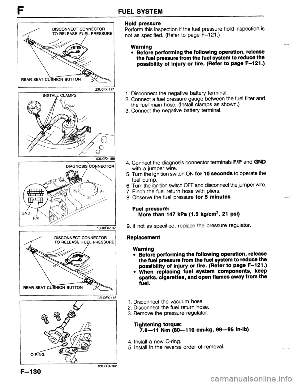
Hold pressure
Perform this inspection if the fuel pressure hold inspection is
not as specified. (Refer to page F-121 .)
Warning
l Before performing the following operation, release
the fuel pressure from the fuel system to reduce the
possibility of injury or fire. (Refer to page F-121 .) ,-
1. Disconnect the negative battery terminal.
2. Connect a fuel pressure gauge between the fuel filter and
the fuel main hose. (Install clamps as shown.)
3. Connect the negative battery terminal.
4. Connect the diagnosis connector terminals
F/P and GND
with a jumper wire.
5. Turn the ignition switch ON
for 10 seconds to operate the
fuel pump.
6. Turn the ignition switch OFF and disconnect the jumper wire.
7. Pinch the fuel return hose with pliers.
8. Observe the fuel pressure
for 5 minutes.
Fuel pressure:
More than 147 kPa (1.5 kg/cm2, 21 psi)
9. If not as specified, replace the pressure regulator.
Replacement
Warning
l Before performing the followlng operation, release
the fuel pressure from the fuel system to reduce the
possibility of injury or flre. (Refer to page F-l 21.)
l When replacing fuel system components, keep
sparks, cigarettes, and open flames away from the
fuel.
1. Disconnect the vacuum hose.
2. Disconnect the fuel return hose.
3. Remove the pressure regulator.
Tightening torque:
7.8-11 N#m (80-110 cm-kg, 89-95 In-lb)
4. Install a new O-ring.
5. Install in the reverse order of removal.
Page 398 of 1164
l Be extremely careful when working with fuel. I
23UOFX.121 Always work away from sparks or open flames.
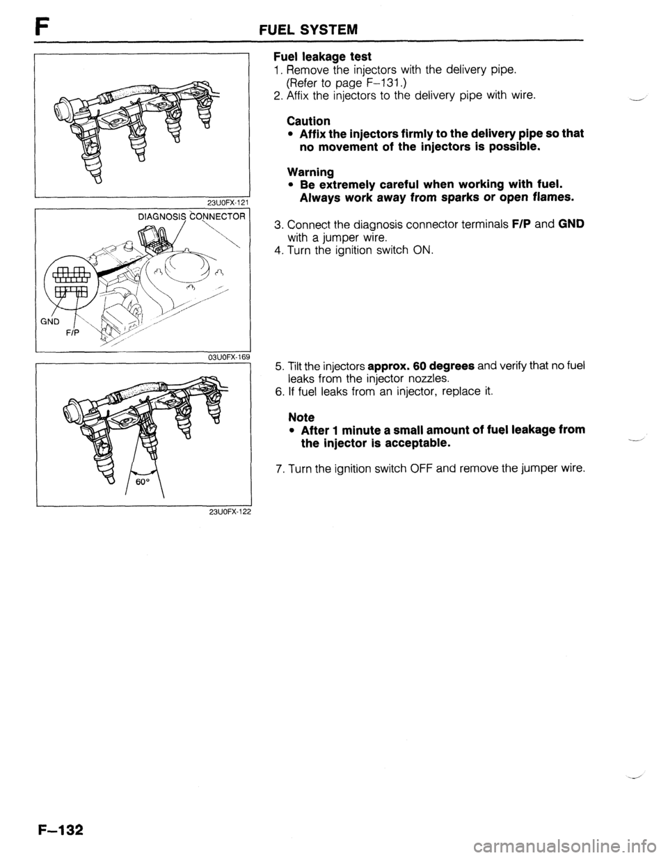
3. Connect the diagnosis connector terminals F/P and GND
with a jumper wire.
FUEL SYSTEM
Fuel leakage test
1. Remove the injectors with the delivery pipe.
(Refer to page F-l 31.)
2. Affix the injectors to the delivery pipe with wire.
Caution
l Affix the injectors firmly to the delivery pipe so that
no movement of the injectors is possible.
-
Warning
4. Turn the ignition switch ON.
03UOFX-16’
23UOFX-12 9 5. Tilt the injectors approx. 60 degrees and verify that no fuel
leaks from the injector nozzles.
6. If fuel leaks from an injector, replace it.
Note
l After 1 minute a small amount of fuel leakage from
the injector Is acceptable.
7. Turn the ignition switch OFF and remove the jumper wire.
-i
F-l 32
Page 411 of 1164

DECHOKE CONTROL SYSTEM t-
DECHOKE CONTROL SYSTEM
DESCRIPTION
To facilitate starting the engine when the spark plugs become fouled, such as when the engine is flooded,
fuel injection is cut if the throttle valve is held wide open while cranking and the engine coolant temperature
is O°C (32OF) or below. This allows the spark oluas to drv and purges excess fuel from the cylinders.
f-- ECU _
. IGNITION SWITCH (START)
l ENGINE SPEED BELOW 500 rpm ’
l THROTTLE VALVE FULLY OPEN
l ENGINE COOLANT TEMPERATURE ;
BELOW
0% (32°F) I FUEL CUT
OBUOFX-19
I / / ‘ I
SYSTEM OPERATION
1.
2. Check if the engine coolant temperature is below O°C
(32OF).
If the engine coolant temperature is above O°C (32OF), dis-
connect the water thermosensor connector and connect an
approx. 10 kB resistor to the connector.
03UOFX.198 3. Turn the ignition switch to START and verify that the injec-
OBUOFX-19! 3
tor operating sound is heard.
4. Depress the accelerator pedal fully and turn the ignition
switch START. Verify that no injector operating sound is
heard.
F-l 45
Page 416 of 1164

CONTROL SYSTEM
Terminal voltage (MTX)
VB: Battery voltage
wminal Input Output Connection to Test condition Correct voltage Remark
1A - - Battery Constant VB For backup
1B 0 Main relay OFF OV
(FUEL INJ relay) Ignition switch ._-
ON VB
1c 0 Ignition switch While cranking Approx. 10V
(START) -
Ignition switch ON ov
10 0 Self-Diagnosis Test switch at “SELF-TEST” With Self-
Checker Lamp illuminated for 3 sec. after ignition 4.5--5.5v Diagnosis Check-
(Monitor lamp) switch OFF+ON er and System
Lamp not illuminated after 3 sec. VEI Selector
Test switch at “02 MONITOR” at idle
Monitor lamp illuminated 4.5-5.5v
Test switch at
“02 MONITOR” at idle
Monitor lamp not illuminated Va
1E 0 Malfunction indica- Lamp illuminated for 3 sec. after ignition
Below 2.5V With System
tor lamp (MIL) switch OFF-ON Selector test
Lamp not illuminated after 3 sec.
VB switch at
“SELF-TEST”
Lamp illuminated Below 2.5V
Lamp not illuminated VR
1F
0 Self-Diagnosis Buzzer sounded for 3 sec. after ignition
Below 2.5V
l With Self-
Checker switch OFF+ON Diagnosis
(Code Number)
Buzzer not sounded after 3 sec. VE - Checker and
Buzzer sounded Below 2.5V System Selector
l With System
Buzzer not sounded
VB Selector test
switch at
“SELF-TEST”
1G 0 Igniter Ignition switch ON ov
-
Idle Approx. 0.2V
1H - - - - - -
_-
II - - - - - -
1J
0 AIC relay Ignition switch ON
VB
A/C switch ON at idle Below 2.5V
A/C switch OFF at idle VB
-
1K 0 Diagnosis
connector
(TEN terminal) System Selector test switch at
“02 MONITOR”
System Selector test switch at
“SELF-TEST” VB
ov Ignition switch
ON
1L 0 DRL relay
(Canada) Parking brake pulled with ignition switch
Ve
l DRL.: Daytime
ON (DRL OFF) Running Lights
Idle (DRL ON) Below 2.5V
V’
F-l 50
Page 417 of 1164

CONTROL SYSTEM F
VB: Battery voltage
incorrect voltage POBSible cause
Alwvs OV’ l ROOM IOA fuse burned l Open circuit in wiring from ROOM IOA fuse to ECU terminal 1A
Always OV
l Main relay malfunction (Refer to page F-171) l Open or short circuit in wiring from main relay to ECU terminal 1B
I
Always OV (Starter turns) l Open or short circuit in wiring from starter interlock switch (USA), ignition
switch (CANADA), to ECU terminal 1C
I
Always OV
Always Vs
Always approx. 5V
l Main relay (FUEL IWJ relay) malfunction (Refer to page F-171) l Open circuit in wiring from main relay to diagnosis connector terminal +B l Open or short circuit in wiring from diagnosis connector terminal MEN to
ECU terminal 1D
l Poor connection at ECU connector l ECU malfunction
l ECU malfunction
Always below
23 MIL always ON
MIL never ON
l Short circuit in wiring from combination meter to ECU terminal 1E l ECU malfunction
l Open circuit in wiring from combination meter to ECU terminal 1E
I
Always Ve l Poor connection at ECU connector l ECU malfunction
Always below
2.5V
Always
VB
No display on Self- * Main relay (FUEL INJ relay) malfunction (Refer to page F-171)
Diagnosis Checker l Open circuit in wiring from main relay to diagnosis connector terminal +B
“88” displayed and
l Open or short circuit in wiring from diagnosis connector terminal FEN to
buzzer sounds con- ECU terminal 1F
tinuously
l Poor connectron at ECU connector l ECU malfunction
Always OV
l Short circuit in wiring from igniter to ECU terminal 1G
I -
I -
I
I -
I -
I
Always below
2.5V
Always VB AIC does not operate l A/C relay malfunction (Refer to page U-55) l Open circurt in wiring from ignition switch to A/C relay l Open circuit in wiring from A/C relay to ECU terminal 1J
A/C switch OFF but
l Short circuit in wiring from A/C relay to ECU terminal IJ
AIC operates l ECU malfunction
l Poor connection at ECU connector l ECU malfunction
Always below l.OV
l Short circuit in wiring from diagnosis connector terminal TEN to ECU termi-
nal 1K
Always Vs
l Open circuit in wiring from diagnosis connector terminal TEN to ECU termi-
nal 1K
l Open circuit in wiring from diaonosis connector terminal GND to ground
Always below
2.W
Always Va DRL ON when ignition
l Short circuit in wiring from DRL relay to ECU terminal IL
switch ON l Short circuit in wiring from DRL relay to DRL unit
DRL never ON
l Open circuit in wiring from DRL relay to ignition switch
l Parking brake switch always ON l DRL unit malfunction (Refer to page T-33)
23UOFX- 134
F-l 51
Page 418 of 1164

F CONTROL SYSTEM
VB: Battery voltage
erminal Input Output Connection to Test condition Corrsct voltage Remark
1M - - - - - -
IN 0 Throttle sensor Accelerator pedal released ov Ignition switch
(Idle switch)
Accelerator pedal depressed
VB ON
10 0
1P 0 Stoplight switch
P/S pressure
switch Brake pedal released
Brake pedal depressed
Ignition switch ON
P/S ON at idle
P/S OFF at idle ov
-
VEi
Va
ov
VS -
10 0 A/C switch A/C switch ON
A/C switch OFF Below 23 Ignition switch
VS ON and blower
motor ON
1R 0
IS 0 Fan switch
Blower control
switch Fan operating (Engine coolant tempera-
ture over 97% (207OF) or diagnosis con-
nector terminal TFA grounded)
Fan not operating (Idle)
Blower control switch OFF or 1st position
Blower control switch 2nd or higher po-
sition ov
-
V0
Ve ignition switch
ov ON
IT 0 Rear window
defroster switch Rear window defroster switch OFF
Rear window defroster switch ON ov
VB
Ignition switch ON
1u 0
iv 0 Headlight switch
Neutral/Clutch
switches Headlights ON
Headlights OFF
Neutral position or clutch pedal
depressed
Others V0
-
ov
ov
VB -
1 I lr----t
r-i
ul r
2Y 2w 2u 2s 20 20 2M 2K 21 2G 2E 2’3 2A 1lJ 1s IQ 10 1M 1K 11 1G 1E 1~ 1A
22 2x 2v 2T 2R 2P 2N 2L 2J 34 2t= 2D 28 Ii/ fT 1R 1p IN 1L 1J 1H 1F 1D 18
F-l 52