MERCEDES-BENZ SPRINTER 2015 MY15 Operator’s Manual
Manufacturer: MERCEDES-BENZ, Model Year: 2015, Model line: SPRINTER, Model: MERCEDES-BENZ SPRINTER 2015Pages: 334, PDF Size: 5.94 MB
Page 171 of 334
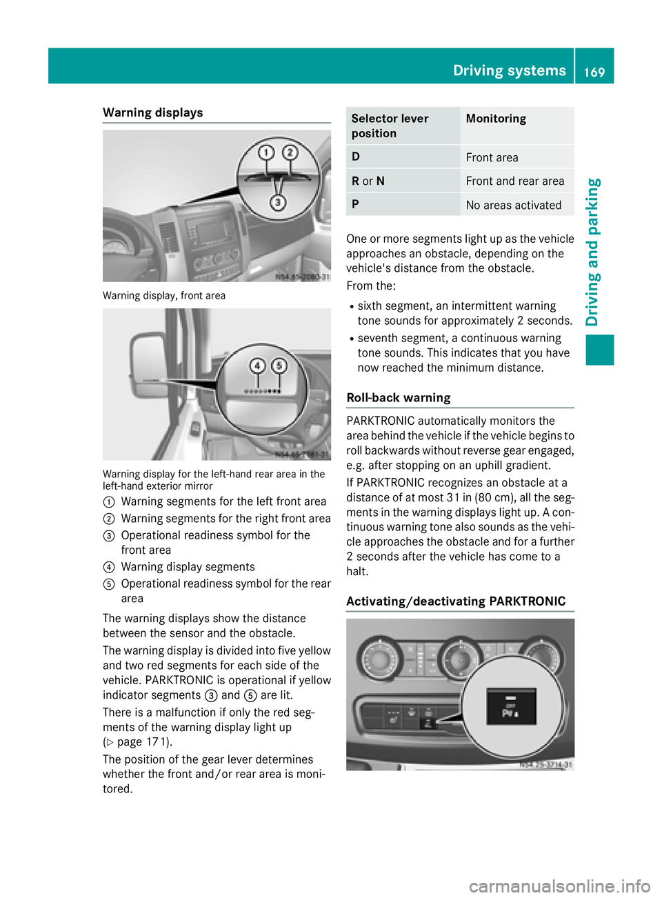
Warning displays
Warning display, front area
Warning display for the left-hand rear area in the
left-hand exterior mirror
0043 Warning segments for the left front area
0044 Warning segments for the right front area
0087 Operational readiness symbol for the
front area
0085 Warning display segments
0083 Operational readiness symbol for the rear
area
The warning displays show the distance
between the sensor and the obstacle.
The warning display is divided into five yellow and two red segments for each side of the
vehicle. PARKTRONIC is operational if yellow
indicator segments 0087and 0083are lit.
There is a malfunction if only the red seg-
ments of the warning display light up
(Y page 171).
The position of the gear lever determines
whether the front and/or rear area is moni-
tored. Selector lever
position Monitoring
D
Front area
R
or N Front and rear area
P
No areas activated
One or more segments light up as the vehicle
approaches an obstacle, depending on the
vehicle's distance from the obstacle.
From the:
R sixth segment, an intermittent warning
tone sounds for approximately 2 seconds.
R seventh segment, a continuous warning
tone sounds. This indicates that you have
now reached the minimum distance.
Roll-back warning PARKTRONIC automatically monitors the
area behind the vehicle if the vehicle begins to
roll backwards without reverse gear engaged,
e.g. after stopping on an uphill gradient.
If PARKTRONIC recognizes an obstacle at a
distance of at most 31 in (80 cm), all the seg- ments in the warning displays light up. A con-
tinuous warning tone also sounds as the vehi- cle approaches the obstacle and for a further
2 seconds after the vehicle has come to a
halt.
Activating/deactivating PARKTRONIC Driving systems
169Driving and parking Z
Page 172 of 334
X
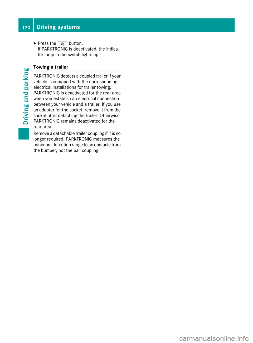
Press the 0069button.
If PARKTRONIC is deactivated, the indica-
tor lamp in the switch lights up.
Towing a trailer PARKTRONIC detects a coupled trailer if your
vehicle is equipped with the corresponding
electrical installations for trailer towing.
PARKTRONIC is deactivated for the rear area when you establish an electrical connection
between your vehicle and a trailer. If you use
an adapter for the socket, remove it from the socket after detaching the trailer. Otherwise,
PARKTRONIC remains deactivated for the
rear area.
Remove a detachable trailer coupling if it is no longer required. PARKTRONIC measures the
minimum detection range to an obstacle fromthe bumper, not the ball coupling. 170
Driving systemsDriving and parking
Page 173 of 334
Problems with PARKTRONIC
Problem
Possible causes/consequences and
0050
0050Solutions Only the red segments
in the PARKTRONIC
warning displays are lit.
A warning tone also
sounds for approx-
imately 2 seconds.
PARKTRONIC is deacti-
vated after approx-
imately 20 seconds.
The indicator lamp of
the 0069 button lights
up and the red seg-
ments in the
PARKTRONIC warning
display go out. PARKTRONIC has malfunctioned and has switched itself off.
X If problems persist, have PARKTRONIC checked at a qualified
specialist workshop. The PARKTRONIC
warning displays
implausible distances.
For example, all the
segments may be lit
even though there is no
obstacle present. The PARKTRONIC sensors are dirty or iced up.
X Clean the PARKTRONIC sensors (Y page 268).
X Turn the key to position 2again in the ignition lock. The license plate or other parts attached near the sensors may not
be secured correctly.
X Check the license plate and attachment parts near the sensors
for correct seating. An external radio or ultrasonic source may be causing interfer-
ence.
X Check PARKTRONIC functions in a different location. Rear view camera
Important safety notes !
Objects that are not at ground level
appear further away than they actually are, for example:
R the bumper of the vehicle parked behind
R the drawbar of a trailer
R the ball coupling of a trailer tow hitch
R the tail-end of a truck
R slanted posts Only use the image from the rear view cam-
era as a guide. You may otherwise damageyour vehicle and/or the object.
The rear view camera is only an aid. It cannot
replace your own awareness of the immedi-
ate surroundings. You are responsible for
safe maneuvering, parking and pulling away.
When maneuvering, parking and pulling away, make sure that there are no persons, animals
or objects in the maneuvering area.
The rear view camera is a visual parking aid.
Information on operation can be found in the
separate Audio 15 supplement. Driving systems
171Driving and parking Z
Page 174 of 334
The camera is in the middle of the roof above
the high-mounted brake lamp (Y page 269).
The rear view camera may show obstacles in perspectival distortion, incorrectly or not at
all. The rear view camera cannot display all
objects located very near and/or under the
rear bumper. It does not warn you of a colli-
sion, persons or objects.
The area behind the vehicle is displayed in a
mirrored fashion, as in the rear-view mirror or
the exterior mirrors.
The function of the rear view camera may be
partially or completely impaired in the follow-
ing circumstances:
R it is raining very heavily or snowing, or it is
foggy.
R the parking space is located in a very dark
place.
R the camera is exposed to very strong white
light. White stripes may appear on the dis-
play.
R the surrounding area is illuminated with flu-
orescent light. The display may flicker.
R if the temperature changes very quickly, for
example if you drive into a heated garage in the winter.
R ambient temperatures are very high.
R the camera lens is dirty or obstructed.
R the rear of the vehicle is damaged. In this
case, have the position and setting
checked at a specialist workshop.
The rear view camera is activated when you
engage reverse gear R.
You can find information on cleaning the cam-
era in the "Maintenance and care" section
(Y page 269). Working mode
ADR (working speed governor)
General notes When activated, ADR automatically increases
the engine speed to a preset speed or a speed
you have set.
i After a cold start, the idling speed of the
engine is increased automatically. If the
preset working speed is lower than the
increased idling speed, the working speed
is only reached once the engine has com-
pleted the warm-up phase.
It is only possible to activate ADR with the
vehicle stationary and the parking brake
applied.
The selector lever of the automatic trans-
mission must be in position P.
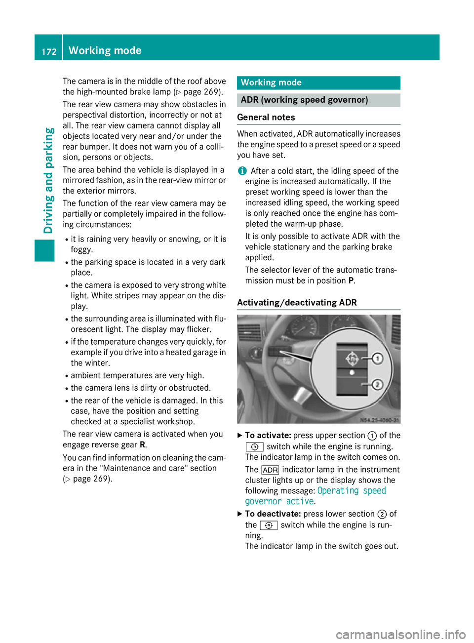
Activating/deactivating ADR X
To activate: press upper section 0043of the
0091 switch while the engine is running.
The indicator lamp in the switch comes on.
The 004E indicator lamp in the instrument
cluster lights up or the display shows the
following message: Operating speed Operating speed
governor active
governor active.
X To deactivate: press lower section 0044of
the 0091 switch while the engine is run-
ning.
The indicator lamp in the switch goes out. 172
Working modeDriving and parking
Page 175 of 334
ADR is automatically deactivated if:
R you release the parking brake.
R the brake pedal is depressed.
R the vehicle moves.
R the control unit detects a malfunction.
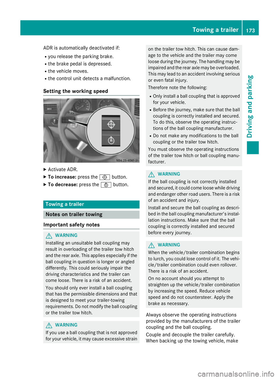
Setting the working speed X
Activate ADR.
X To increase: press the0091button.
X To decrease: press the0092button. Towing a trailer
Notes on trailer towing
Important safety notes G
WARNING
Installing an unsuitable ball coupling may
result in overloading of the trailer tow hitch
and the rear axle. This applies especially if the ball coupling in question is longer or angled
differently. This could seriously impair the
driving characteristics and the trailer can
come loose. There is a risk of an accident.
You should only ever install a ball coupling
that has the permissible dimensions and that
is designed to meet your trailer-towing
requirements. Do not modify the ball coupling
or the trailer tow hitch. G
WARNING
If you use a ball coupling that is not approved for your vehicle, it may cause excessive strain on the trailer tow hitch. This can cause dam-
age to the vehicle and the trailer may come
loose during the journey. The handling may be
impaired and the rear axle may be overloaded.
This may lead to an accident involving serious
or even fatal injury.
Therefore note the following:
R Only install a ball coupling that is approved
for your vehicle.
R Before the journey, make sure that the ball
coupling is correctly installed and secured.
To do this, observe the operating instruc-
tions of the ball coupling manufacturer.
R Do not make any modifications to the ball
coupling or the trailer tow hitch.
You must observe the operating instructions
of the trailer tow hitch or ball coupling manu-
facturer. G
WARNING
If the ball coupling is not correctly installed
and secured, it could come loose while driving and endanger other road users. There is a risk
of an accident and injury.
Install and secure the ball coupling as descri-
bed in the ball coupling manufacturer's instal- lation instructions. Make sure that the ball
coupling is correctly installed and secured
before every journey. G
WARNING
When the vehicle/trailer combination begins
to lurch, you could lose control of it. The vehi- cle/trailer combination could even rollover.
There is a risk of an accident.
On no account should you attempt to
straighten up the vehicle/trailer combination
by increasing the speed. Reduce vehicle
speed and do not countersteer. Apply the
brake as necessary.
Always observe the operating instructions
provided by the manufacturers of the trailer
coupling and the ball coupling.
Couple and decouple the trailer carefully.
When backing up the towing vehicle, make Towing a trailer
173Driving and parking Z
Page 176 of 334
sure nobody is standing between the vehicle
and the trailer.
A trailer which is incorrectly coupled to the
towing vehicle could break away. A correctly
coupled trailer must be positioned horizon-
tally behind the towing vehicle.
Ensure that the following weights are not
exceeded:
R the permissible noseweight
R the permissible trailer load
R the permissible rear axle load of the towing
vehicle
R the permissible gross weight of both the
towing vehicle and the trailer
R the permissible gross combination weight
The applicable permissible values that may
not be exceeded can be found:
R in your vehicle documents
R on the type plates for the trailer tow hitch
R on the type plates for the trailer
R on the vehicle identification plate
(Y page 316).
Where the values differ, the lowest is valid.
You will find values approved by the manu-
facturer on the identification plates and those
for the towing vehicle in the "Permissible
trailer loads and trailer drawbar noseweights"
section (Y page 177).
Your vehicle behaves differently with a trailer than without one.
The vehicle/trailer combination:
R is heavier
R is restricted in its acceleration and gradi-
ent-climbing capability
R has an increased braking distance
R is more susceptible to strong crosswinds
R requires more sensitive steering
R has a larger turning circle
This may impair the handling characteristics. When towing a trailer, always adjust your
speed to suit the road and weather condi-
tions. Drive carefully. Maintain a safe dis-
tance. If you require any further explanation of the
information contained in the Operator's Man-
ual, please contact an authorized Sprinter
dealer.
General notes R
Observe the legally prescribed maximum
speed for vehicle/trailer combinations in
the relevant country, state or Canadian
province. Before setting off, check the vehi-
cle documents of the your trailer to find out
the permissible maximum speed.
This reduces the risk of accidents.
R Install only an approved trailer coupling on
your vehicle. Only use a ball coupling that is
approved for your vehicle and Sprinter
trailer tow hitch. More information on the
availability, mounting and installation of the
trailer electrics is available at any qualified specialist workshop.
R The turn signals on the trailer are only guar-
anteed to function when incandescent
bulbs are used. You can obtain more infor-
mation about installing the trailer electrics
at any qualified specialist workshop.
R The trailer coupling is one of the most
important vehicle parts with regard to road
safety. The notes on operation, care and
maintenance issued by the manufacturer
should be observed.
R The bumpers of your vehicle are not suita-
ble for installing detachable trailer cou-
plings.
R Do not attach rented trailer tow hitches or
other detachable trailer tow hitches to the
bumper.
R Minimize the risk of damage to the ball cou-
pling. If you do not require the ball coupling,
remove it from the ball coupling recess.
Weight information can be found in the “Per-
missible trailer and drawbar noseweights”
section (Y page 177).
i The height of the ball neck changes
according to the load on the vehicle. If this 174
Towing a trailerDriving and parking
Page 177 of 334
is case, use a trailer with a height-adjusta-
ble trailer drawbar.
Driving tips The maximum permissible speed for vehicle/
trailer combination depends on the type of
trailer. Before setting off, check the vehicle
documents of the your trailer to find out the
permissible maximum speed. Observe the
legally prescribed maximum speed for vehi-
cle/trailer combinations in the relevant coun-
try, state or Canadian province.
When towing a trailer, your vehicle's handling
characteristics will be different in comparison to when driving without a trailer and it will
consume more fuel.
On long, steep downhill slopes you must
select shift range 3,2or 1in good time.
i This also applies if cruise control is acti-
vated.
This enables you to utilize the engine's brak-
ing effect and you do not need to brake so
heavily to keep the correct speed, which pro-
tects the brake system and prevents the
brakes from overheating and wearing too
quickly. If you need to brake additionally, to
not depress the brake pedal constantly, but
periodically.
Driving tips If the trailer begins to swing from side to side:
X Do not accelerate.
X Do not counter-steer.
X Brake if necessary.
i You can reduce the risk of the trailer
swinging and rocking by retrofitting anti-
roll bars or trailer stability programs. More information is available from your author-
ized Sprinter Dealer.
R Maintain a greater distance than you would
when driving without towing a trailer.
R Avoid sudden braking. Apply the brakes
gently at first to allow the trailer brake to overrun. Then, increase the brake force
quickly.
R The figures for the gradient climbing capa-
bilities from a standstill refer to sea level.
When driving in mountainous areas, note
that the power output of the engine, and
with it its gradient climbing capability,
decrease with increasing altitude. Coupling up a trailer
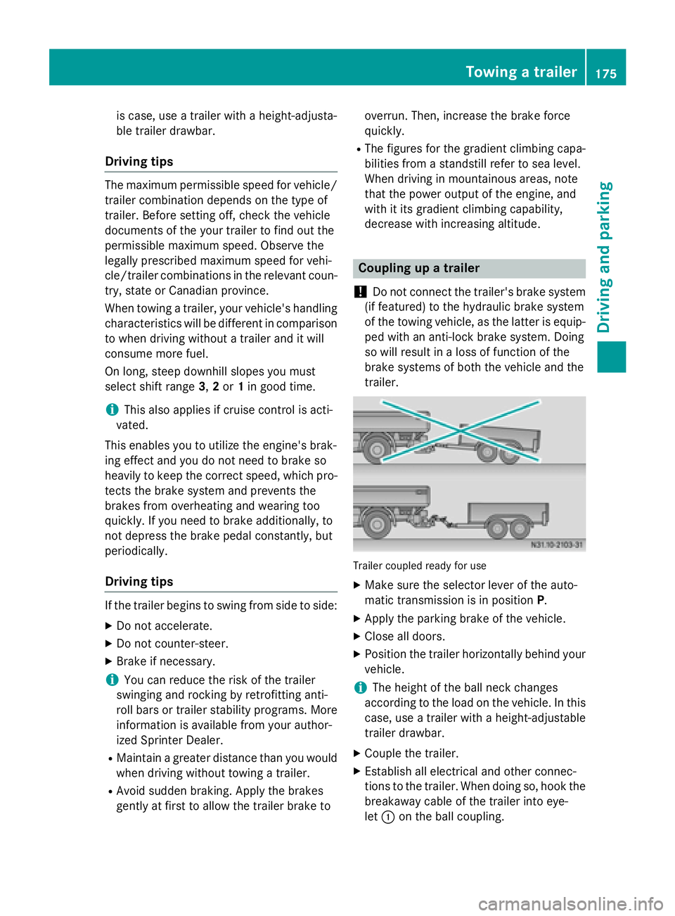
! Do not connect the trailer's brake system
(if featured) to the hydraulic brake system
of the towing vehicle, as the latter is equip- ped with an anti-lock brake system. Doing
so will result in a loss of function of the
brake systems of both the vehicle and the
trailer. Trailer coupled ready for use
X Make sure the selector lever of the auto-
matic transmission is in position P.
X Apply the parking brake of the vehicle.
X Close all doors.
X Position the trailer horizontally behind your
vehicle.
i The height of the ball neck changes
according to the load on the vehicle. In this
case, use a trailer with a height-adjustable
trailer drawbar.
X Couple the trailer.
X Establish all electrical and other connec-
tions to the trailer. When doing so, hook the
breakaway cable of the trailer into eye-
let 0043 on the ball coupling. Towing a trailer
175Driving and parking Z
Page 178 of 334
X
Remove the objects that are preventing the
trailer from rolling, e.g. wheel chocks.
X Release the trailer parking brake.
i The subharness of the vehicle has a cable
connection to the brake lamp indicator
lamp.
Observe the maximum permissible trailer
dimensions (width and length).
Most federal states and all Canadian provin-
ces require by law:
R safety chains between the towing vehicle
and the trailer. The chains should be cross-
wound under the trailer drawbar. They must be fastened to the vehicle's trailer cou-
pling, not to the bumper or the axle.
Leave enough slack in the chains. This
allows you to drive round tight corners.
R a separate brake system for certain types
of trailer.
R a safety switch for braked trailers. Find out
the specific requirements according to the
applicable laws.
If the trailer detaches from the towing vehi- cle, the safety switch applies the trailer's
brakes. Towing a trailer
There are numerous legal requirements con-
cerning the towing of a trailer, e.g. speed
restrictions. Make sure your vehicle/trailer
combination complies with local laws. This
not only means where you live, but also any-
where you are driving to. Information is avail-
able from the police and local authorities.
Observe the following when towing a trailer:
R Practice driving around bends, stopping
and backing up at a place where there is no
traffic. This enables you to gain experience and get used to the new handling charac-
teristics.
R Before driving, check:
- that the trailer tow hitch and ball cou-
pling are secure
- that the safety switch for a braked trailer
is functioning properly
- that the safety chains are secure and not
damaged
- that the electrical connections are
secure
- that the lights are working
- that the wheels are in good order and the
tire pressure is correct
R Adjust the exterior mirrors to provide an
unobstructed view of the rear section of the
trailer.
R If the trailer has electronically controlled
brakes, pull the vehicle/trailer combina-
tion away carefully. Brake manually using
the brake controller and check that the
brakes are working.
R Secure the load on the trailer according to
the applicable specifications and current
standards on securing loads (Y page 242).
R When driving with a trailer, check at regular
intervals that the load is secured and that
the brakes and lights are working.
R Bear in mind that the handling will be less
stable when towing a trailer than when driv-
ing without one. Avoid sudden steering
movements.
R The vehicle/trailer combination is heavier,
accelerates more slowly and has a
decreased gradient climbing capability and
a longer braking distance.
It is more susceptible to crosswinds and
requires cautious steering.
R If possible, do not brake suddenly, but
rather moderately at first so that the trailer
can activate its brakes. Then increase the
force on the brake pedal.
R If the automatic transmission repeatedly
shifts between gears when driving on 176
Towing a trailerDriving and pa
rking
Page 179 of 334
inclines, restrict the shift range. Select shift
range 4,3, 2or 1.
Driving in a low gear and at a low speed
reduces the risk of damaging the engine.
R When driving on a downhill gradient, shift to
a low gear and take advantage of the
engine's braking effect.
Avoid continuous brake application as this
may overheat the vehicle brakes and, if
installed, the trailer brakes.
R If the coolant temperature increases dra-
matically while the air-conditioning system
is switched on, switch off the air-condition-
ing system.
Coolant heat can also be dissipated by
switching the airflow and the temperature
of the heater/air conditioning to the maxi-
mum level. Open the windows if necessary.
R When overtaking, pay particular attention
to the extended length of your vehicle/
trailer combination.
Due to the length of your vehicle/trailer
combination you need an additional dis-
tance before you can return to your original
lane. Uncoupling a trailer
G
WARNING
If you uncouple a trailer with the overrun
brake engaged, you could trap your hand
between the vehicle and the trailer drawbar.
There is a risk of injury.
Do not uncouple a trailer if the overrun brake is engaged.
! Do not disconnect a trailer with an
engaged overrun brake. Otherwise, your
vehicle could be damaged by the rebound- ing of the overrun brake.
X Make sure the selector lever of the auto-
matic transmission is in position P.
X Apply the parking brake of the vehicle.
X Close all doors. X
Apply the parking brake of the trailer.
X In addition, secure the trailer against rolling
away with a wheel chock or similar object.
X Remove the trailer cable and safety chains
and decouple the trailer. Permissible trailer loads and trailer
drawbar noseweights
Weight information !
On vehicles with a permissible gross vehi-
cle weight of 11030 lbs (5003 kg), the per- missible gross combination weight is less
than the total of the permissible gross vehi-
cle weight and the permissible trailer load.
Exceeding the permissible gross combina-
tion weight can lead to damage to the driv-
etrain, to the transmission or to the trailer
tow hitch.
If the vehicle or the trailer is fully laden, the relevant value for the permissible gross
vehicle weight or the permissible trailer
load is therefore lower. In this case, the
trailer or the vehicle may only be partially
loaded.
The gross trailer weight (GTW) is calculated by adding the weight of the trailer to the weight
of the load and equipment.
The maximum gross vehicle weight is vehicle-specific and equipment-dependent: 5,000 lbs
(2,268 kg) or 7,500 lbs (3,402 kg).
The maximum perm issible trailer drawbar
noseweight on the ball coupling is 500 lbs
(227 kg) or 750 lbs (340 kg). Theactual nose-
weight may not exceed the value given on the
identification plates of the trailer tow hitch or
the trailer. If the values vary, the lowest value always applies.
The gross combination weight rating (GCWR)is calculated by adding the gross weight of the
trailer to the gross vehicle weight including a
driver's weight of approximately 150 lbs
(68 kg). The permissible Gross Combination
Weight Rating is vehicle-specific and depends
on the equipment level. Towing a trailer
177Driving and parking Z
Page 180 of 334
When driving with a trailer, you should not
exceed the permitted Gross Combination
Weight Rating (GCWR).
The permissible values, which must not be
exceeded, can be found in your vehicle docu-
ments and on the trailer tow hitch type plates
for the trailer and the vehicle (Y page 316).
The basic values approved by the manufac-
turer can also be found in the "Technical data" section (Y page 328). If the values vary, the
lowest value always applies.
Loading a trailer !
Utilize the maximum permissible nose-
weight as fully as possible. Do not allow the
weight to fall below the minimum permis-
sible noseweight, otherwise the trailer may
come loose.
R You must distribute the load on the vehicle
and trailer so that the permitted maximum
values for the gross vehicle weight (GVWR), gross trailer weight (GTW) and gross com-
bined weight (GCWR) as well as permitted
gross axle loads (GAWR) and noseweight
(TWR) of your vehicle are not exceeded.
R Add the drawbar noseweight on the ball
coupling (TWR) to the rear axle load. This
will prevent you from exceeding the per-
missible gross axle weight (GAWR).
R Add the drawbar noseweight on the ball
coupling (TWR) to the vehicle payload. This
will prevent you from exceeding the per-
missible gross vehicle weight (GVWR).
Checking the vehicle and trailer weight R
Make sure the weights of the towing vehicle
and the trailer comply with the maximum
permissible values. Have the vehicle/
trailer combination weighed on a calibrated weighbridge. The vehicle/trailer combina-
tion consists of the towing vehicle including
the driver, passengers and load, as well as
the loaded trailer.
R Check the maximum permissible gross axle
weight rating of the front and rear axles (GAWR), the gross trailer weight (GTW), the
gross combination weight rating (GCWR)
and the noseweight of the trailer drawbar
(TWR). Trailer power supply
! Incorrect wiring of the connector plug
could, under certain circumstances, cause
malfunctions in the vehicle's other elec-
tronic systems. We therefore recommend
having the connector plug wired at a quali-
fied specialist workshop.
! You can connect accessories with a max-
imum power consumption of 240 W to the
permanent power supply.
You must not charge a trailer battery using
the power supply.
Your vehicle may be equipped with various
electrical installations for trailer towing.
Depending on your trailer, you may need an
adapter to connect the electrical system of
the trailer with that of the vehicle.
The trailer socket of your vehicle is equipped at the factory with a permanent power supply.
The permanent power supply is on the trailer
socket pin assignment 4.
Note that the permanent power supply of the
trailer is not switched off when the on-board
voltage is low. This can completely discharge the starter battery of your vehicle.
The turn signals on the trailer are only guar-
anteed to function when incandescent bulbs
are used.
Further information on the electrical equip-
ment currently installed on your vehicle and
on installing trailer electrics can be obtained
at any qualified specialist workshop. 178
Towing a trailerDriving and parking