MITSUBISHI 3000GT 1991 Service Manual
Manufacturer: MITSUBISHI, Model Year: 1991, Model line: 3000GT, Model: MITSUBISHI 3000GT 1991Pages: 1146, PDF Size: 76.68 MB
Page 311 of 1146
15-I
I
k..INTAKE AND ~
EXHAUST
=
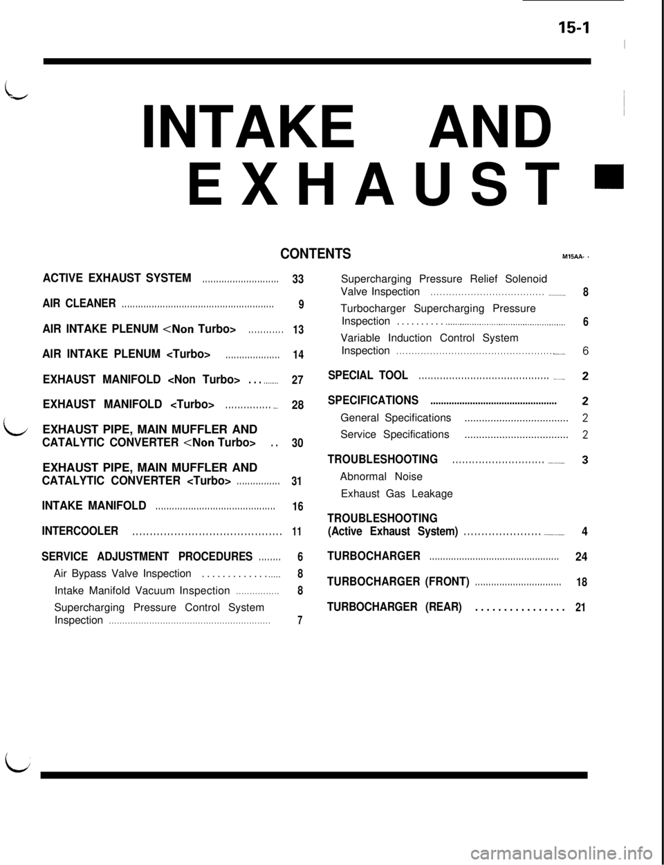
CONTENTSME.AA- -
ACTIVE EXHAUST SYSTEM. . . . . . . . . . . . . . . . . . . . . . . . . . . .
AIR CLEANER. . . . . . . . . . . . . . . . . . . . . . . . . . . . . . . . . . . . . . . . . . . . . . . . . . . . . . . .
AIR INTAKE PLENUM
AIR INTAKE PLENUM
EXHAUST MANIFOLD
EXHAUST MANIFOLD
LEXHAUST PIPE, MAIN MUFFLER ANDCATALYTIC CONVERTER
CATALYTIC CONVERTER
INTAKE MANIFOLD. . . . . . . . . . . . . . . . . . . . . . . . . . . . . . . . . . . . . . . . . . . .
INTERCOOLER. . . . . . . . . . . . . . . . . . . . . . . . . . . . . . . . . . . . . . . . . . .
SERVICE ADJUSTMENT PROCEDURES. . . . . . . .Air Bypass Valve Inspection
. . . . . . . . . . . . . .._..Intake Manifold VacuumInspection
. . . . . . . . . . . . . . . .Supercharging Pressure Control System
Inspection
. . . . . . . . . . . . . . . . . . . . . . . . . . . . . . . . . . . . . . . . . . . . . . . . . . . . . . . . . . . .
33
9
13
14
27
28
30
31
16
11
6
8
8
7Supercharging Pressure Relief Solenoid
ValveInspection
. . . . . . . . . . . . . . . . . . . . . . . . . . . . . . . . . . . . . .._........Turbocharger Supercharging Pressure
Inspection
. . . . . . . . . . .._................................._.___.........Variable Induction Control System
Inspection
. . . . . . . . . . . . . . . . . . . . . . . . . . . . . . . . . . . . . . . . . . . . . . . . . . . . .._.....
SPECIAL TOOL. . . . . . . . . . . . . . . . . . . . . . . . . . . . . . . . . . . . . . . . . . . .._____..
SPECIFICATIONS................................................General Specifications
....................................Service Specifications
....................................
TROUBLESHOOTING. . . . . . . . . . . . . . . . . . . . . . . . . . . . .._._.._....Abnormal Noise
Exhaust Gas Leakage
TROUBLESHOOTING
(Active Exhaust System)
. . . . . . . . . . . . . . . . . . . . . . ..________....
TURBOCHARGER. . . . . . . . . . . . . . . . . . . . . . . . . . . . . . . . . . . . . . . . . . . . . . . .
TURBOCHARGER(FRONT). . . . . . . . . . . . . . . . . . . . . . . . . . . . . . . .
TURBOCHARGER (REAR). . . . . . . . . . . . . . . .8
6
4
24
18
21
Page 312 of 1146
15-2INTAKE AND EXHAUST - Specifications / Special Tool
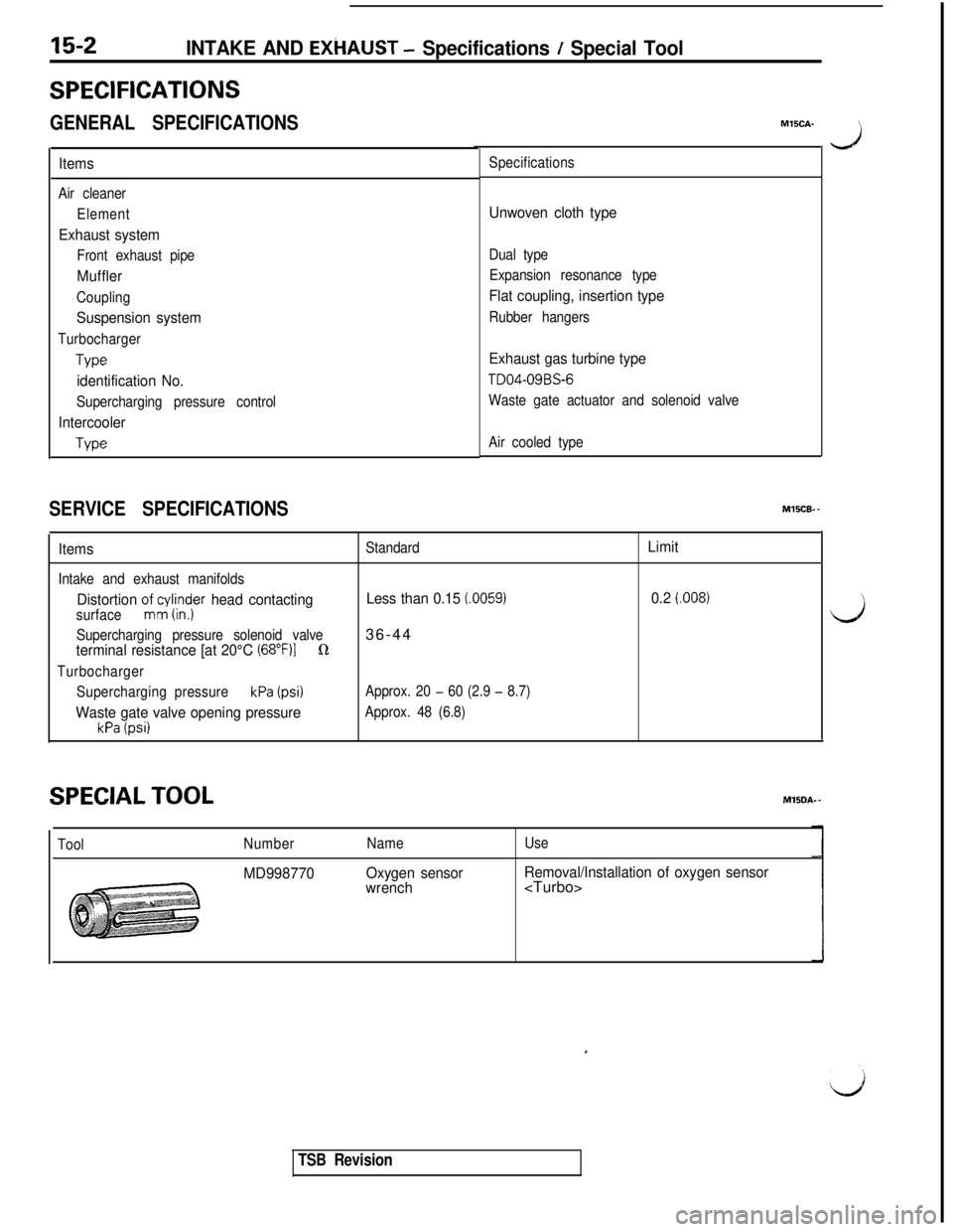
SPECIFICATIONS
GENERAL SPECIFICATIONS
Items
Air cleaner
Element
Exhaust system
Front exhaust pipe
Muffler
Coupling
Suspension system
Turbocharger
We
identification No.
Supercharging pressure control
Intercooler
Type
SERVICE SPECIFICATIONSMlSCA-
Specifications
Unwoven cloth type
Dual type
Expansion resonance type
Flat coupling, insertion type
Rubber hangers
Exhaust gas turbine type
TD04-09BS-6
Waste gate actuator and solenoid valve
Air cooled type
MVXB-.
Items
Intake and exhaust manifolds
Distortion oJcnylirrdjer head contactingsurface
Supercharging pressure solenoid valve
terminal resistance [at 20°C (68”F)lQ
Turbocharger
Supercharging pressure
kPa (psi)
Waste gate valve opening pressure
kPa (psi)
Standard
Less than 0.15 (.0059)36-44
Approx. 20 - 60 (2.9 - 8.7)
Approx. 48 (6.8)
Limit
0.2
f.008)
SPECIAL TOOLMlSDA- -
ToolNumber
MD998770
Name
Oxygen sensor
wrench
Use
Removal/Installation of oxygen sensor
J
iJ
TSB Revision
Page 313 of 1146
INTAKE AND EXHAUST - Troubleshooting15-3
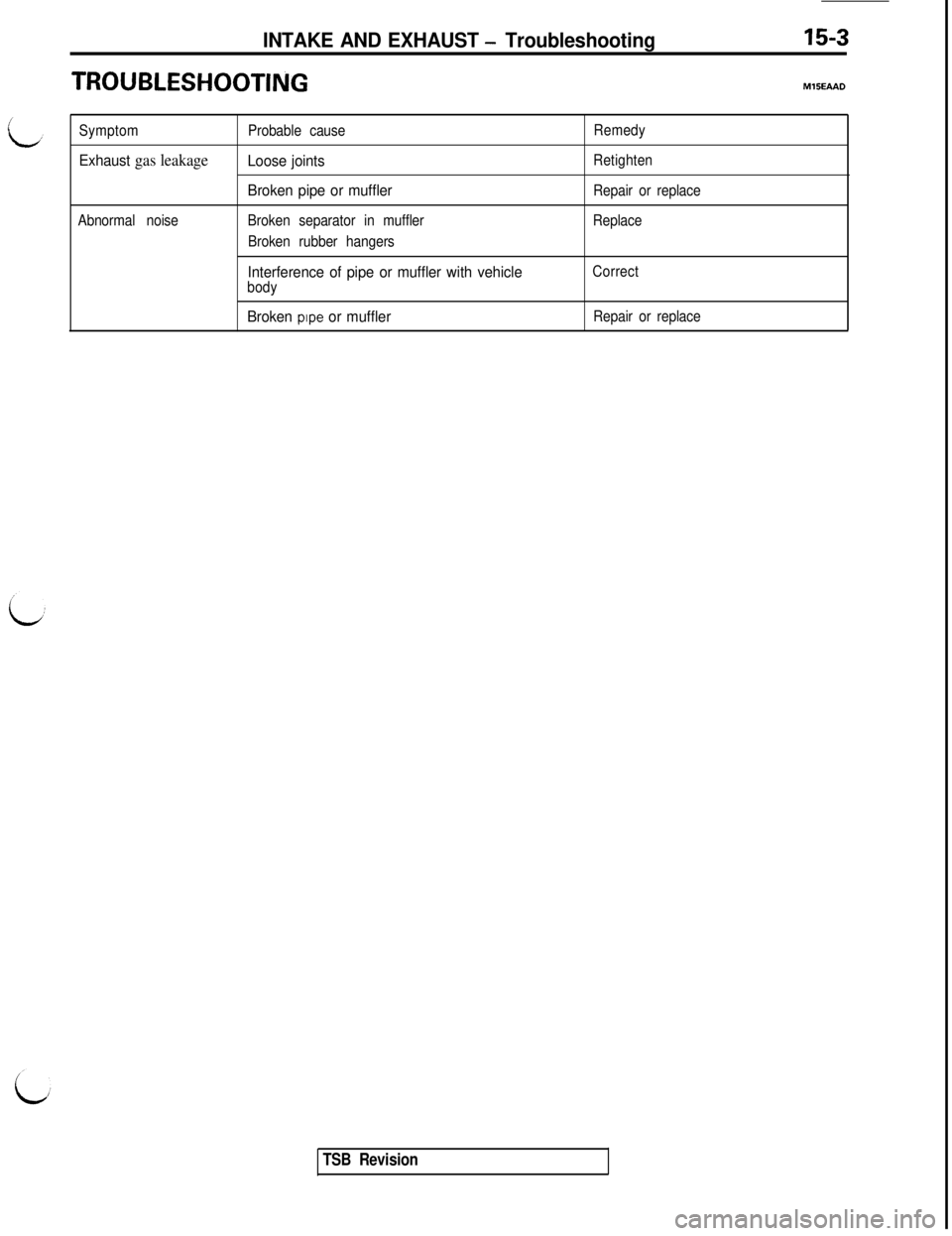
TROUBLESHOOTINGMlSEAAD
Symptom
Exhaust gas leakage
Abnormal noiseProbable cause
Loose joints
Broken pipe or muffler
Broken separator in muffler
Broken rubber hangers
Interference of pipe or muffler with vehiclebody
Broken pipe or muffler
Remedy
Retighten
Repair or replace
Replace
Correct
Repair or replace
TSB Revision
Page 314 of 1146
15-4INTAKE AND EXHAUST -Troubleshooting (Active Exhaust System)
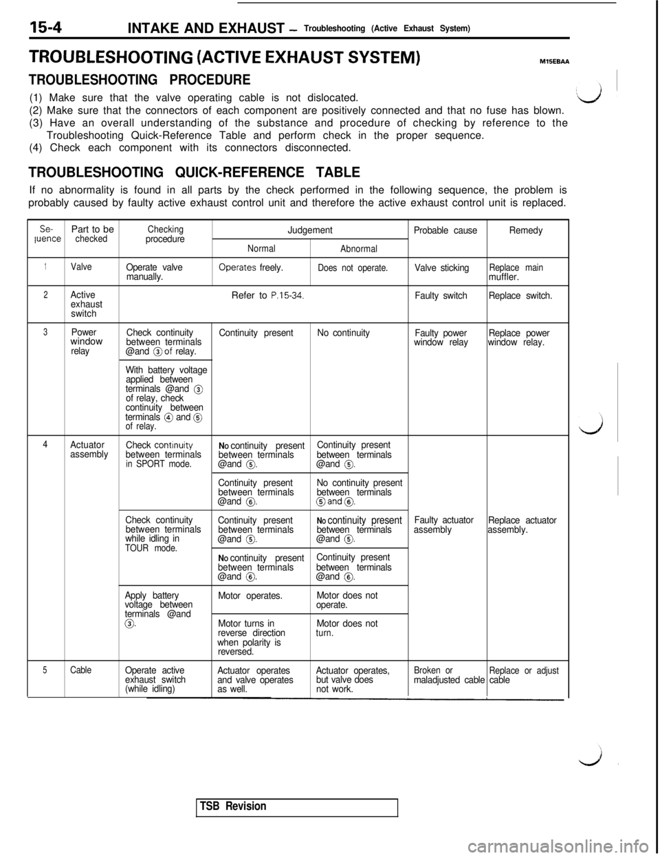
TROUBLESHOOTING (ACTIVE EXHAUST SYSTEM)MlSEBAA
TROUBLESHOOTING PROCEDURE(1) Make sure that the valve operating cable is not dislocated.
(2) Make sure that the connectors of each component are positively connected and that no fuse has blown.
(3) Have an overall understanding of the substance and procedure of checking by reference to the
Troubleshooting Quick-Reference Table and perform check in the proper sequence.
(4) Check each component with its connectors disconnected.
TROUBLESHOOTING QUICK-REFERENCE TABLEIf no abnormality is found in all parts by the check performed in the following sequence, the problem is
probably caused by faulty active exhaust control unit and therefore the active exhaust control unit is replaced.
Se-Part to becheckedCheckingprocedureJudgement
Probable causeluenceRemedy
Normal
Abnormal
1ValveOperate valve
manually.Operates freely.Does not operate.Valve stickingReplace mainmuffler.
2ActiveRefer to P.15-34.exhaustFaulty switchReplace switch.
switch
3PowerwindowCheck continuity
between terminalsContinuity presentNo continuity
Faulty power
relay
@and @of
relay.window relayReplace power
window relay.
With battery voltage
applied between
terminals @and
@of relay, check
continuity between
terminals
@ and @of relay.
4
Actuator
Check contrnuityassembly
between terminalsNO continuity present
between terminalsContinuity present
between terminals
in SPORT mode.@and 0.@and 0.
Continuity present
between terminalsNo continuity present
between terminals
@and
0.@and 0.
Check continuity
between terminalsContinuity present
between terminalsNO continuity presentbetween terminalsFaulty actuator
Replace actuator
while idling in
@and 0.@and @assemblyassembly.
TOUR mode.NO continuity present
between terminalsContinuity present
between terminals
@and
0.@and 0.
Apply battery
Motor operates.Motor does not
voltage between
terminals @andoperate.
0.Motor turns inMotor does not
reverse directionturn.when polarity is
reversed.
5CableOperate activeBroken orexhaust switchActuator operates
and valve operatesActuator operates,
but valve doesReplace or adjust
(while idling)
as well.not work.maladjusted cable cable
TSB Revision
Page 315 of 1146
INTAKE AND EXHAUST -Troubleshooting (Active Exhaust.System)15-5
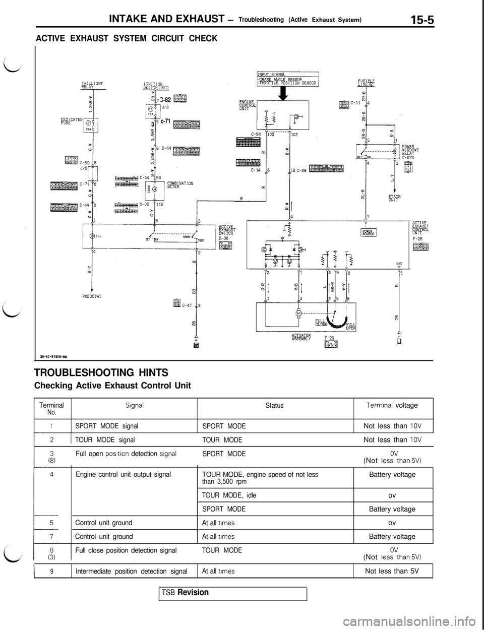
ACTIVE EXHAUST SYSTEM CIRCUIT CHECK
5= i C-82
-i
@g
0J/S1%
‘I
‘6 c-71
3
1
+RHEOSTATmACTUATOR
1::ASSEMBLYF-29
&$jq
ACTlYEFXoQBIlBZ"NIT
TROUBLESHOOTING HINTSChecking Active Exhaust Control Unit
TerminalNo.Signal
StatusTerminal voltage
1SPORT MODE signal
SPORT MODENot less than IOV
I-2 TTOUR MODE signal
TOUR MODENot less than IOV
Full open posrtion detection srgnalSPORT MODE(Not lesi’than 5V)
Engine control unit output signal
Control unit ground
Control unit groundTOUR MODE, engine speed of not lessthan 3,500 rpm
TOUR MODE, idle
SPORT MODE
At all times
At all
trmesBattery voltage
ov
Battery voltage
ov
Battery voltage
IFull close position detection signalTOUR MODE(Not lesk?than 5V)
I9Intermediate position detection signalAt all timesNot less than 5V
TSB Revision
Page 316 of 1146
15-6INTAKE AND EXHAUST - Service Adjustment Procedures
Variable rnductiorcontrol servoconnectors
6FU1277
Open
Close
71 NO105
SERVICE ADJUSTMENT PROCEDURESMlSGlAA
VARIABLE INDUCTION CONTROL SYSTEM IN-
d
SPECTION (Non Turbo)
SYSTEM INSPECTION
(1) Warm up the engine.
(2) Connect the tachometer. (Refer to GROUP 11 - Engine
Adjustment.)
(3) Make sure that when the engine speed is increased from
the idle speed to 5,000 rpm, the induction control valve
shaft turns.
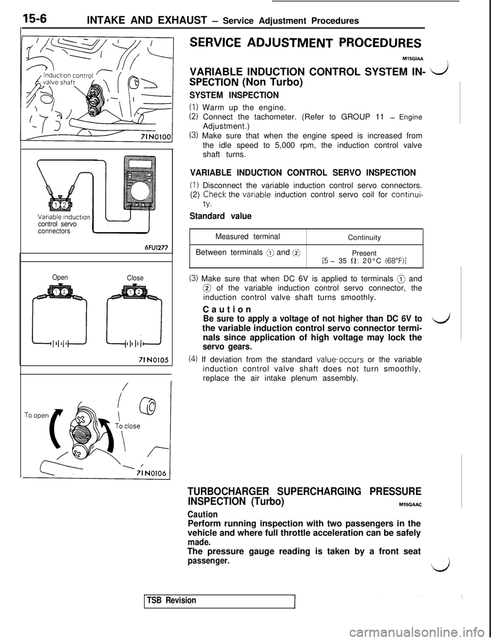
VARIABLE INDUCTION CONTROL SERVO INSPECTION
(1) Disconnect the variable induction control servo connectors.
(2)
Teck the vanable induction control servo coil for continui-
Standard value
Measured terminalBetween terminals
@ and @]Continuity
Present
15 - 35 0: 20°C (68”F)I
(3) Make sure that when DC 6V is applied to terminals @ and@ of the variable induction control servo connector, the
induction control valve shaft turns smoothly.
Caution
Be sure to apply a voltage of not higher than DC 6V tothe variable induction control servo connector termi-4nals since application of high voltage may lock the
servo gears.
(4) If deviation from the standard value.occurs or the variable
induction control valve shaft does not turn smoothly,
replace the air intake plenum assembly.
TURBOCHARGER SUPERCHARGING PRESSURE
INSPECTION (Turbo)MlSGAAC
CautionPerform running inspection with two passengers in the
vehicle and where full throttle acceleration can be safely
made.The pressure gauge reading is taken by a front seat
passenger.‘,k,i
TSB Revision
Page 317 of 1146
INTAKE AND EXHAUST - Service Adiustment Procedures15-7
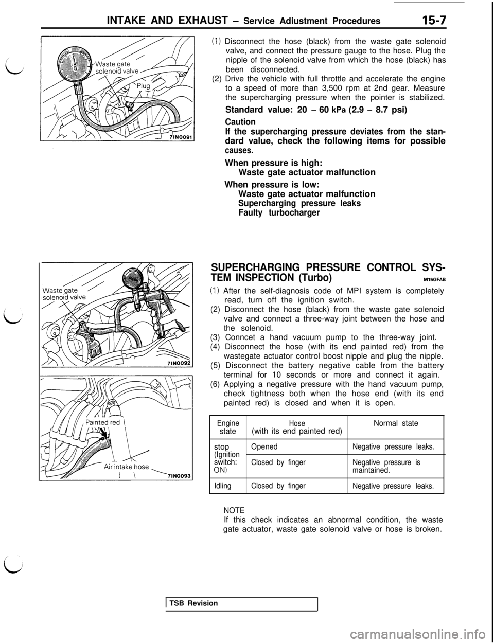
(1) Disconnect the hose (black) from the waste gate solenoid
valve, and connect the pressure gauge to the hose. Plug the
nipple of the solenoid valve from which the hose (black) has
been disconnected.
(2) Drive the vehicle with full throttle and accelerate the engine
to a speed of more than 3,500 rpm at 2nd gear. Measure
the supercharging pressure when the pointer is stabilized.
Standard value: 20
- 60 kPa (2.9 - 8.7 psi)
Caution
If the supercharging pressure deviates from the stan-dard value, check the following items for possible
causes.When pressure is high:
Waste gate actuator malfunction
When pressure is low:
Waste gate actuator malfunction
Supercharging pressure leaks
Faulty turbocharger
SUPERCHARGING PRESSURE CONTROL SYS-
TEM INSPECTION (Turbo)MlSGFAB
(1) After the self-diagnosis code of MPI system is completely
read, turn off the ignition switch.
(2) Disconnect the hose (black) from the waste gate solenoid
valve and connect a three-way joint between the hose and
the solenoid.
(3) Conncet a hand vacuum pump to the three-way joint.
(4) Disconnect the hose (with its end painted red) from the
wastegate actuator control boost nipple and plug the nipple.
(5) Disconnect the battery negative cable from the battery
terminal for 10 seconds or more and connect it again.
(6) Applying a negative pressure with the hand vacuum pump,
check tightness both when the hose end (with its end
painted red) is closed and when it is open.
EngineHoseNormal state
state(with its end painted red)
stop
OpenedNegative pressure leaks.
(Ignition
switch:Closed by fingerNegative pressure is
ON)maintained.
IdlingClosed by finger
Negative pressure leaks.
NOTEIf this check indicates an abnormal condition, the waste
gate actuator, waste gate solenoid valve or hose is broken.
1 TSB Revision
Page 318 of 1146
INTAKE AND EXHAUST - Service Adiustment Procedures
SUPERCHARGING PRESSURE RELIEF SOLENOID
VALVE INSPECTION (Turbo)
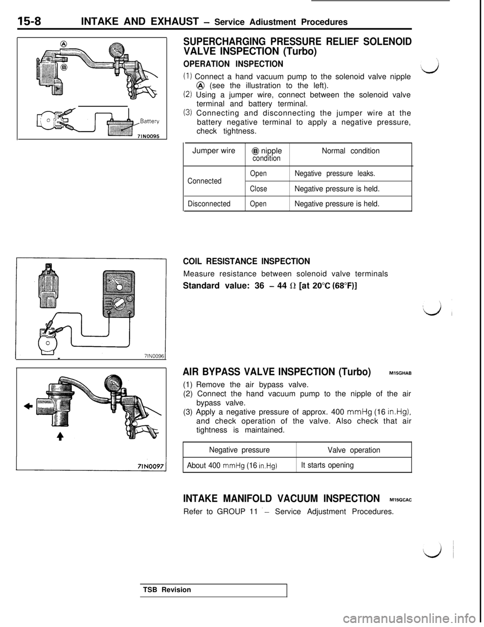
OPERATION INSPECTION
(1) Connect a hand vacuum pump to the solenoid valve nipple@ (see the illustration to the left).
(2) Using a jumper wire, connect between the solenoid valve
terminal and battery terminal.
(3) Connecting and disconnecting the jumper wire at the
battery negative terminal to apply a negative pressure,
check tightness.
Jumper wire
@I nippleNormal conditioncondition
Connected
Disconnected
OpenNegative pressure leaks.
CloseNegative pressure is held.
OpenNegative pressure is held.
COIL RESISTANCE INSPECTIONMeasure resistance between solenoid valve terminals
Standard value: 36
- 44 0 [at 20°C (68”F)I
AIR BYPASS VALVE INSPECTION (Turbo)MlSGHAB
(1) Remove the air bypass valve.
(2) Connect the hand vacuum pump to the nipple of the air
bypass valve.
(3) Apply a negative pressure of approx. 400 mmHg (16
in.Hg),and check operation of the valve. Also check that air
tightness is maintained.
Negative pressure
About 400
mmHg (16 in.Hg)
Valve operation
It starts opening
INTAKE MANIFOLD VACUUM INSPECTIONM’ISGCACRefer to GROUP 11
‘- Service Adjustment Procedures.
TSB Revision
Page 319 of 1146
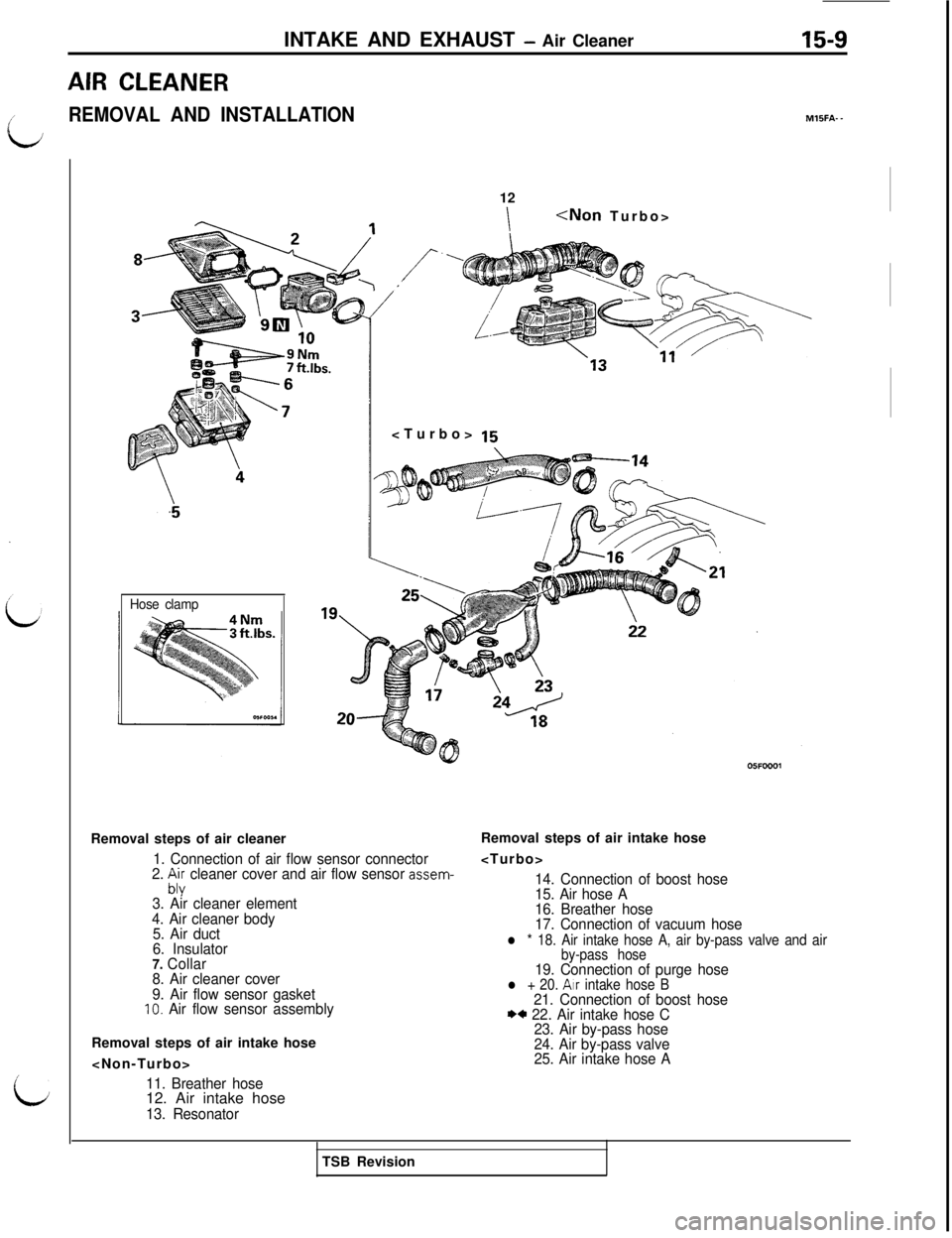
AIR CLEANERINTAKE AND EXHAUST
- Air Cleaner15-9i
REMOVAL AND INSTALLATIONMlIFA- -
/
i
Hose clamp12
I
Removal steps of air cleaner
1. Connection of air flow sensor connector
2. :;; cleaner cover and air flow sensor assem-
3. Air cleaner element
4. Air cleaner body
5. Air duct
6. Insulator
7. Collar
8. Air cleaner cover
9. Air flow sensor gasket
IO. Air flow sensor assemblyRemoval steps of air intake hose
11. Breather hose12. Air intake hose
13. ResonatorRemoval steps of air intake hose
14. Connection of boost hose
15. Air hose A
16. Breather hose
17. Connection of vacuum hose
l * 18. Air intake hose A, air by-pass valve and air
by-pass hose
19. Connection of purge hosel + 20. Atr intake hose B21. Connection of boost hoseI)+ 22. Air intake hose C
23. Air by-pass hose
24. Air by-pass valve
25. Air intake hose ATSB Revision
Page 320 of 1146
15-10INTAKE AND EXHAUST - Air Cleaner
INSPECTIONM15FCAH
&$1Air intake hose C
Air intake hose A
Air intake hose B
105FOO2:
lCheck the air cleaner body, cover or packing for deforma-
tion, corrosion or damage.‘,l Check the air duct for damage.
‘4
lCheck the air cleaner element for clogging, contamination
or damage.
If element is slightly clogged, remove dust by blowing air
from inside of element.
AIR-FLOW SENSOR CHECKFor inspection of air-flow sensor, refer to GROUP 13 -Air-Flow
Sensor Check.
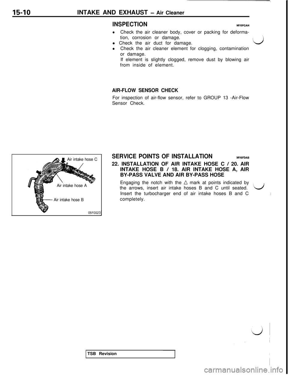
SERVICE POINTS OF INSTALLATIONMl5FDAB
22. INSTALLATION OF AIR INTAKE HOSE C
/ 20. AIR
INTAKE HOSE B
/ 18. AIR INTAKE HOSE A, AIR
BY-PASS VALVE AND AIR BY-PASS HOSE
Engaging the notch with the
n mark at points indicated by
the arrows, insert air intake hoses B and C until seated.
‘$dInsert the turbocharger end of air intake hoses B and C
Icompletely.
TSB Revision