MITSUBISHI 3000GT 1991 Service Manual
Manufacturer: MITSUBISHI, Model Year: 1991, Model line: 3000GT, Model: MITSUBISHI 3000GT 1991Pages: 1146, PDF Size: 76.68 MB
Page 481 of 1146
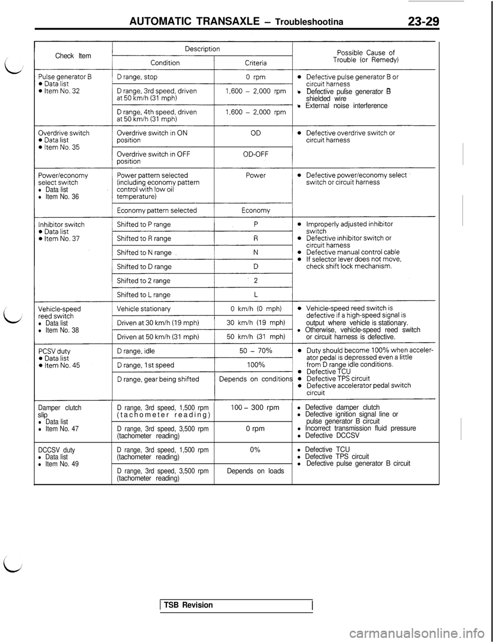
AUTOMATIC TRANSAXLE - Troubleshootina23-29
Check Iteml
Defective pulse generator B
shielded wire
l External noise interference
l Data listl Item No. 36
l Data listl Item No. 38output where vehicleisstationary.l Otherwise, vehicle-speed reed switch
or circuit harness is defective.
Damper clutchslipl Data listl Item No. 47
DCCSV duty
l Data listl Item No. 49D range, 3rd speed, 1,500 rpm(tachometer reading)
D range, 3rd speed, 3,500 rpm(tachometer reading)
D range, 3rd speed, 1,500 rpm(tachometer reading)
D range, 3rd speed, 3,500 rpm(tachometer reading)
100 - 300 rpm
0 rpm
0%
Depends on loads
l Defective damper clutchl Defective ignition signal line or
pulse generator B circuit
l Incorrect transmission fluid pressurel Defective DCCSV
l Defective TCUl Defective TPS circuitlDefective pulse generator B circuit
1 TSB Revision
Page 482 of 1146
23-30AUTOMATIC TRANSAXLE - Troubleshooting
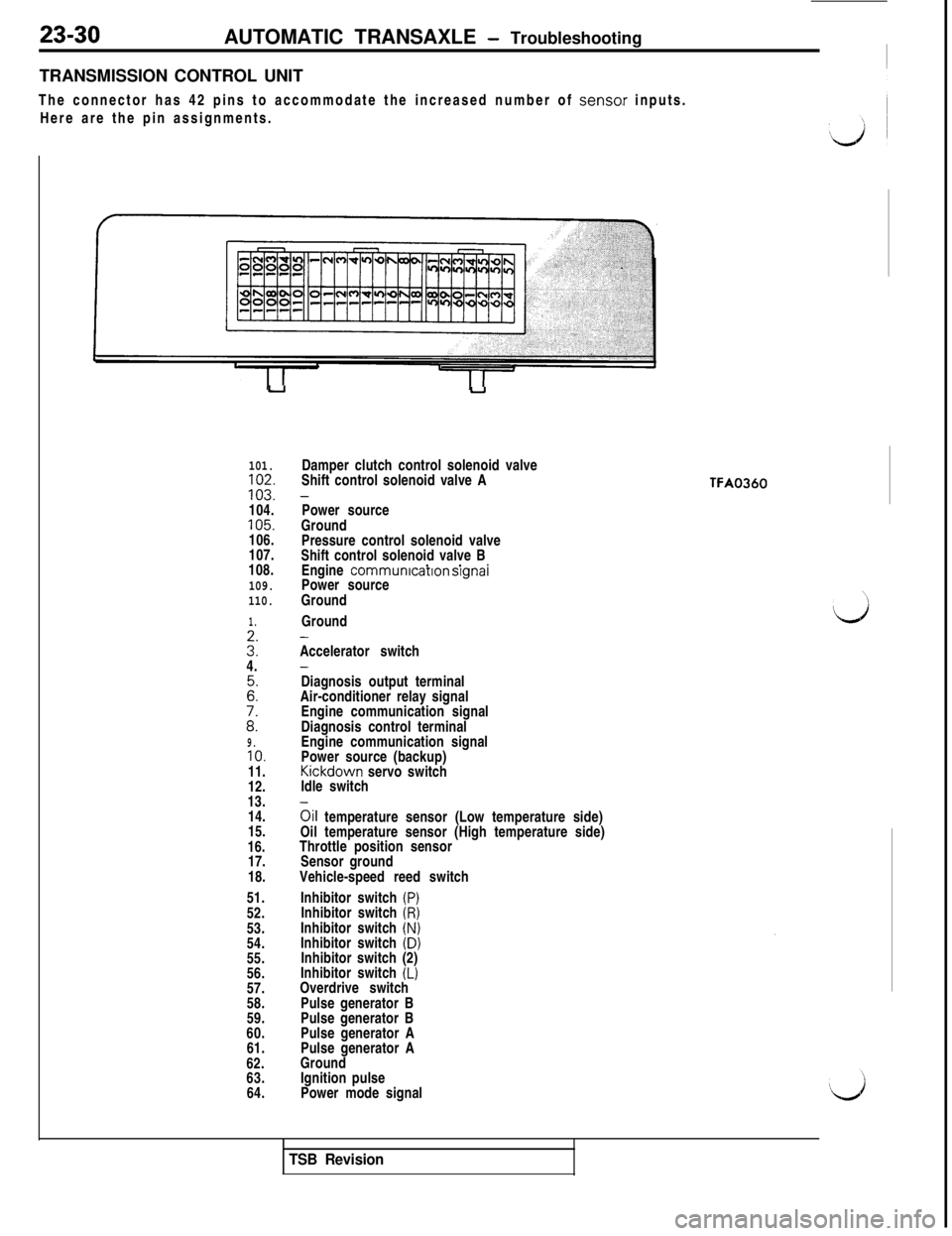
TRANSMISSION CONTROL UNIT
The connector has 42 pins to accommodate the increased number of senso.r inputs.
Here are the pin assignments.
uu
101.102.103.
104.105.
106.
107.
108.
109.
110.
1.
3':4.
Z:
i:9.10.11.
12.
13.
14.
15.
16.
17.
18.
51.
52.
53.
54.
55.
56.
57.
58.
59.
60.
61.
62.
63.
64.Damper clutch control solenoid valve
Shift control solenoid valve A
-Power source
Ground
Pressure control solenoid valve
Shift control solenoid valve B
. .
*Engine communrcatron srgnaiPower source
Ground
Ground
-Accelerator switch
-Diagnosis output terminal
Air-conditioner relay signal
Engine communication signal
Diagnosis control terminal
Engine communication signal
Power source (backup)Kickdown servo switch
Idle switch
oil temperature sensor (Low temperature side)
Oil temperature sensor (High temperature side)
Throttle position sensor
Sensor ground
Vehicle-speed reed switch
Inhibitor switch
(P)Inhibitor switch (R)Inhibitor switch (N)Inhibitor switch (D)
Inhibitor switch (2)
Inhibitor switch
(L)Overdrive switch
Pulse generator B
Pulse generator B
Pulse generator A
Pulse generator A
Ground
Ignition pulse
Power mode signal
TFA0360
TSB Revision
Page 483 of 1146
AUTOMATIC TRANSAXLE - Troubleshooting
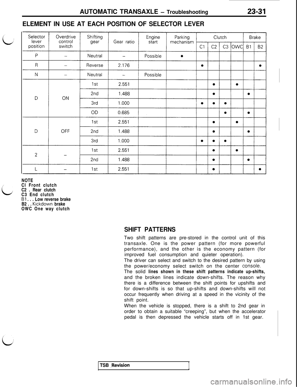
ELEMENT IN USE AT EACH POSITION OF SELECTOR LEVER
23-31NOTE
/
LCl Front clutch
C2 . Rear clutch
C3 End clutch
Bl . . . Low reverse brake
B2 . . Kickdown brake
OWC One way clutch
SHIFT PATTERNSTwo shift patterns are pre-stored in the control unit of this
transaxle. One is the power pattern (for more powerful
performance), and the other is the economy pattern (for
improved fuel consumption and quieter operation).
The driver can select and switch to the desired pattern by using
the power/economy select switch on the center
Iconsole.The solid lines shown in these shift patterns indicate up-shifts,
and the broken lines indicate down-shifts. The reason why
there is a difference between the shift points for upshifts and
for down-shifts is so that up-shifts and down-shifts will not
occur frequently when driving at a speed in the vicinity of the
shift point.
When the vehicle is stopped, there is a shift to 2nd gear in
order to obtain a suitable “creeping”, but when the accelerator
pedal is then depressed the vehicle starts off in 1st gear.
TSB .Revision1
Page 484 of 1146
23-32AUTOMATIC TRANSAXLE - Troubleshooting
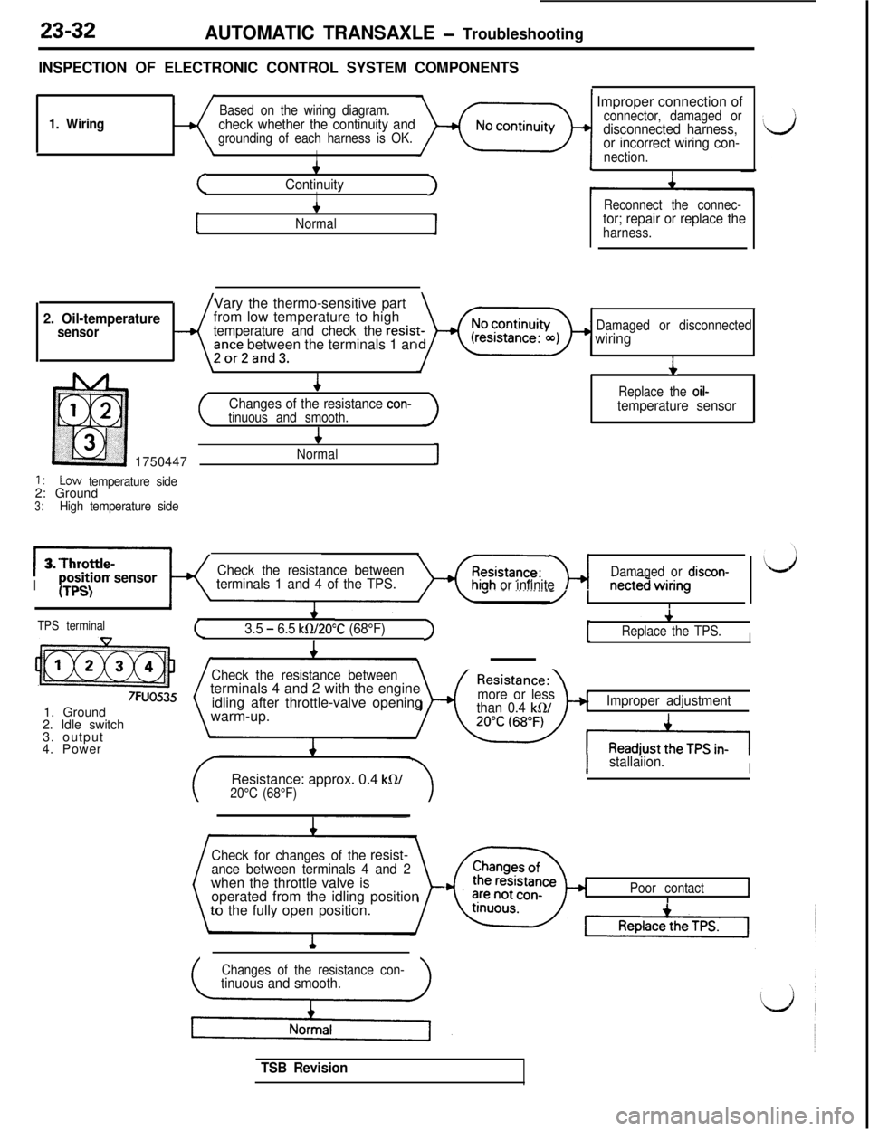
INSPECTION OF ELECTRONIC CONTROL SYSTEM COMPONENTS
1. WiringBased on the wiring diagram.check whether the continuity andgrounding of each harness is OK.
I
(
4
ContinuityII
+
Normal~ Improper connection of
connector, damaged ordisconnected harness,
or incorrect wiring con-
nection.
I
Reconnect the connec-tor; repair or replace theharness.Vary the thermo-sensitive part
2. Oil-temperaturefrom low temperature to highsensortemperature and check theresist-Damaged or disconnected
ante between the terminals 1 anwiring2or2and3.
4
J
Changes of the resistance con-Replace the oil-
tinuous and smooth.temperature sensor
41750447
Normal1
1:LOW temperature side2: Ground
3:High temperature side
I:3. Throttle-
K
Check the resistance between
Ip~~~t,ion sensorterminals 1 and 4 of the TPS.hiah or infinitem- -----inecteciI-
\ IDamaged or discon-..----Awiring
I
c3.5 - 6.5 kW20”C (68°F)t
v
Replace the TPS.I>ITPS terminal
7FUO5351. Ground
2. Idle switch
3. output
4. Power
Check the resistance betweenterminals 4 and 2 with the engine
idling after throttle-valve opening
warm-up.
Resistance: approx. 0.4
kR/20°C (68°F)
Changes of the resistance con-
tinuous and smooth.
/Resistance:\more or less
than 0.4 kQ/Improper adjustment
Istallaiion.I
Check for changes of theresist-ance between terminals 4 and 2when the throttle valve is
operated from the idling position
o the fully open position.
Poor contactII
TSB Revision
Page 485 of 1146
AUTOMATIC TRANSAXLE - Troubleshooting23-33
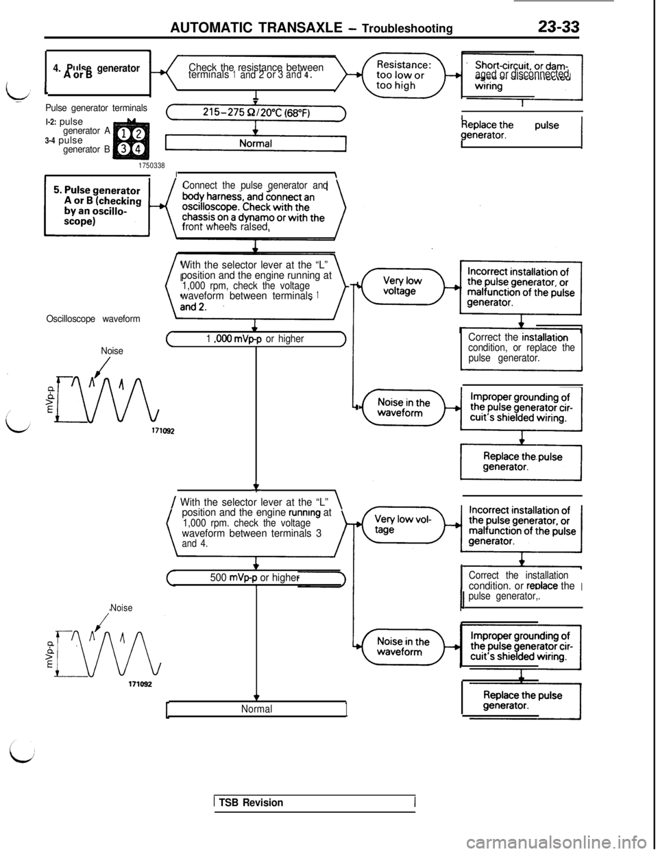
4. Pulse generatorCheck the resistance betweenAorBterminals1and 2or3and4.agedordisconnected
iv1-Pulse generator terminalsl-2: pulse
generator A3-4 pulse
generator B
17503381I\Connect the pulse generator and
front wheels raised.
Oscilloscope waveform
With the selector lever at the “L”
position and the engine running at
1,000 rpm, check the voltagewaveform between terminals1(
1 .OOO mVp-p or higher
Noise>
iJh
171092
f\/ With the selector lever at the “L”\
position and the engine running at1,000 rpm. check the voltagewaveform between terminals 3and 4.
I
1fWWF;tf: pulse /
Correct the inst.allationcondition, or replace the
pulse generator.
L-
*
500 mVp-p or higherI
Noise
ICorrect the installationcondition. or redace theI1 pulse generator,.1
171092
*
Normal1
1 TSB Revision
Page 486 of 1146
23-34AUTOMATIC TRANSAXLE - Troubleshooting
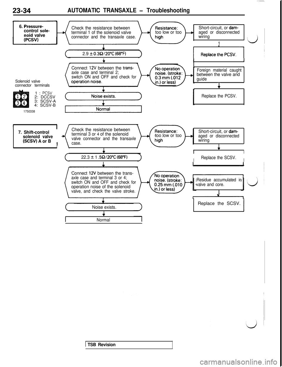
6. Pressure-control sole-noid valve
Check the resistance between
terminal 1 of the solenoid valve
connector and the transaxle case.
too low or tooShort-circuit, or dam-aged or disconnectedwiring
1IJ
2.9 + 0.3Q/20°C (68°F)
Solenoid valve
connector terminals1:
PCSV2: DCCSV
3: SCSV-A
4: SCSV-B
1750338
II7. Shift-controlsolenoid valve(SCSV) A or Bt
II
c
Connect 12V between the trans-
axle case and terminal 2;
switch ON and OFF and check for
I1
Foreign material caught-l
between the valve andguide
4
Replace the PCSV.
Check the resistance between
terminal 3 or 4 of the solenoidvalve connector and the transaxle
case.
&
Short-circuit, or dam-toolow or tooaged or disconnectedwiring
I4I
22.3 + 1 .5R/20°C (68°F)IReplace the SCSV.I
Connect 12V between the trans-axle case and terminal 3 or 4;
switch ON and OFF and check for
operation noise of the solenoidvalve, and check the valve stroke.Residue accumulated in
valve and core.1
Noise exists.I
1 Replace the SCSV. 1
+
Normal
1 TSB Revision
Page 487 of 1146
AUTOMATIC TRANSAXLE - Troubleshooting
~I+~Pull the parking brake to
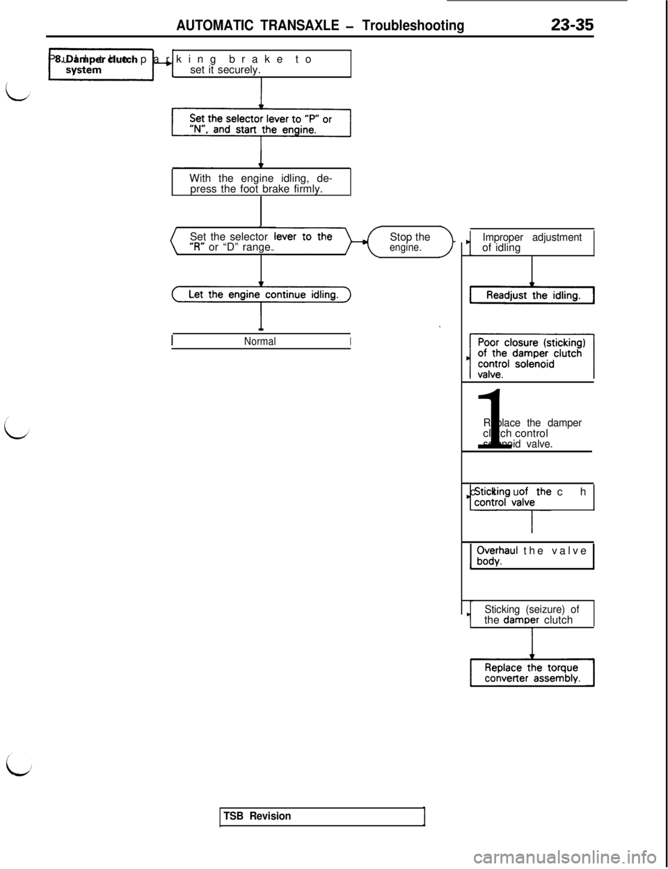
set it securely.
I
23-35With the engine idling, de-
press the foot brake firmly.
.
Set the selector
‘3” or “D” range.Stop theengine.Let the engine continue idling.
c .
INormalI
Improper adjustmentof idling
-Readjust1
Replace the damperclutch control
solenoid valve.
1 9$4nFv;itheclutch 1
1 f;w$aul the valve 1
Sticking (seizure) ofthe damDer clutch
TSB Revision
Page 488 of 1146
23-36AUTOMATIC TRANSAXLE - Troubleshootina
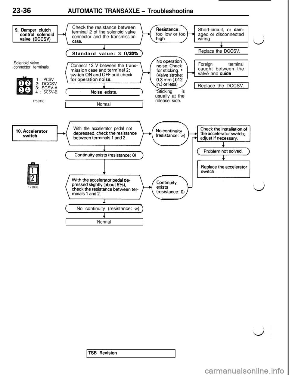
9. Damper clutch
control solenoid
valve (DCCSV)Check the resistance betweenterminal 2 of the solenoid valve
connector and the transmission
case.
?Short-circuit, or
dam-toolow or too
aged or disconnected
wiring
I
Solenoid valve
connector terminals1:
PCSV2: DCCSV
3: SCSV-A
4:
SCSV-B
1750338
( Standard value: 3 fWO% 1
Connect 12 V between the trans-
*Sticking
isusually at the
release side.
*
Replace the DCCSV.
Foreignterminalcaught between the
valve and
guide
1 Replace the DCCSV. J
INormal1
With the accelerator pedal not
171096
(No continuity (resistance: a~) )
INormalI
TSB Revision
Page 489 of 1146
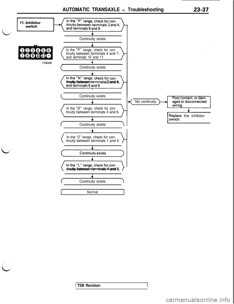
AUTOMATIC TRANSAXLE - Troubleshooting23-37
i
Continuity exists
/’
b
In the “R” range, check for con-tinuity between terminals 4 and 7,and terminals 10 and 11.
Continuity exists,
(t}tinuity between termrnals 2 and 4,
L.Continuity exists
4
In the
ti D“ range, check for con-tinuity between terminals 4 and 6.
c
+
Continuity exists\I
In the “2” range, check for con-
tinuity between terminals 1 and 4.
gzizkzgtinuity between terminals 4 and 5.
c
4
Continuity exists-I
NormalI
No continuity
/ P$f the inhibitor/
1 TSB Revision
Page 490 of 1146
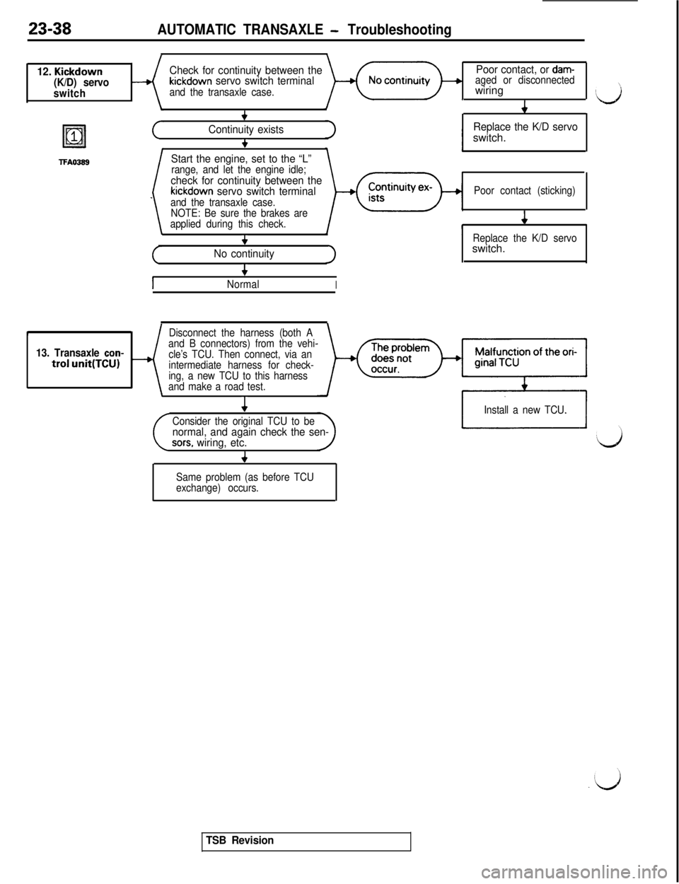
23-38AUTOMATIC TRANSAXLE - Troubleshooting
12. Kickdown
(K/D) servo
switch
19=111
TFAO389
Check for continuity between thePoor contact, or dam-
kickdown servo switch terminalaged or disconnected
and the transaxle case.wiring
+c
Continuity existsReplace the K/D servo
+switch.
Start the engine, set to the “L”range, and let the engine idle;check for continuity between thekickdown servo switch terminalPoor contact (sticking)
and the transaxle case.
NOTE: Be sure the brakes are
applied during this check.4
+Replace the K/D servo
No continuityswitch.
+I
NormalIr
Disconnect the harness (both A
13. Transaxle con-and B connectors) from the vehi-
trol unit(TCU)cle’s TCU. Then connect, via an
intermediate harness for check-
ing, a new TCU to this harness
and make a road test.4
Install a new TCU.
Consider the original TCU to be
normal, and again check the sen-sors. wiring, etc.
4
Same problem (as before TCU
exchange) occurs.
TSB Revision