MITSUBISHI 3000GT 1991 Service Manual
Manufacturer: MITSUBISHI, Model Year: 1991, Model line: 3000GT, Model: MITSUBISHI 3000GT 1991Pages: 1146, PDF Size: 76.68 MB
Page 701 of 1146
REAR SUSPENSION
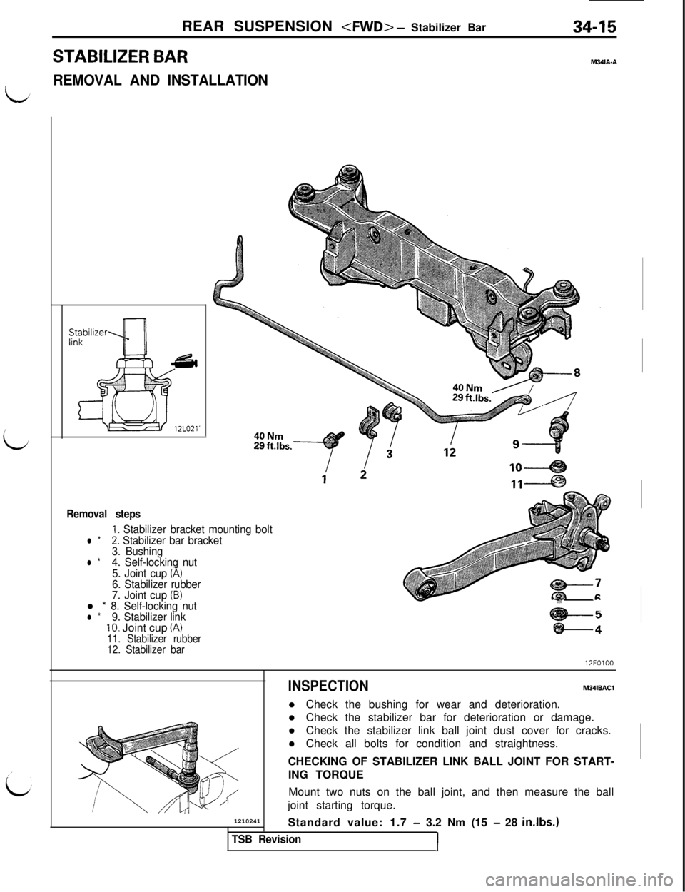
STABILIZER BARM341A.A
/REMOVAL AND INSTALLATION
i
,’
id
Removal steps
1. Stabilizer bracket mounting boltl *2. Stabilizer bar bracket
3. Bushing
l *4. Self-locking nut
5. Joint cup (A)6. Stabilizer rubber
7. Joint cup (B)l * 8. Self-locking nutl *9. Stabilizer link10. Joint cup (A)11. Stabilizer rubber
12. Stabilizer bar
-5
t:(I
-Z’-
@+-----4l?FOlOO
1210241
INSPECTIONMWBACll Check the bushing for wear and deterioration.
l Check the stabilizer bar for deterioration or damage.
l Check the stabilizer link ball joint dust cover for cracks.
l Check all bolts for condition and straightness.
CHECKING OF STABILIZER LINK BALL JOINT FOR START-
ING TORQUE
Mount two nuts on the ball joint, and then measure the ball
joint starting torque.
Standard value: 1.7
- 3.2 Nm (15 - 28 in.lbs.1
TSB RevisionI
Page 702 of 1146
34-16
REAR SUSPENSION
CGrinafiMultipurpose
grease
12LO21-
\12LO24:Hold with
wrench
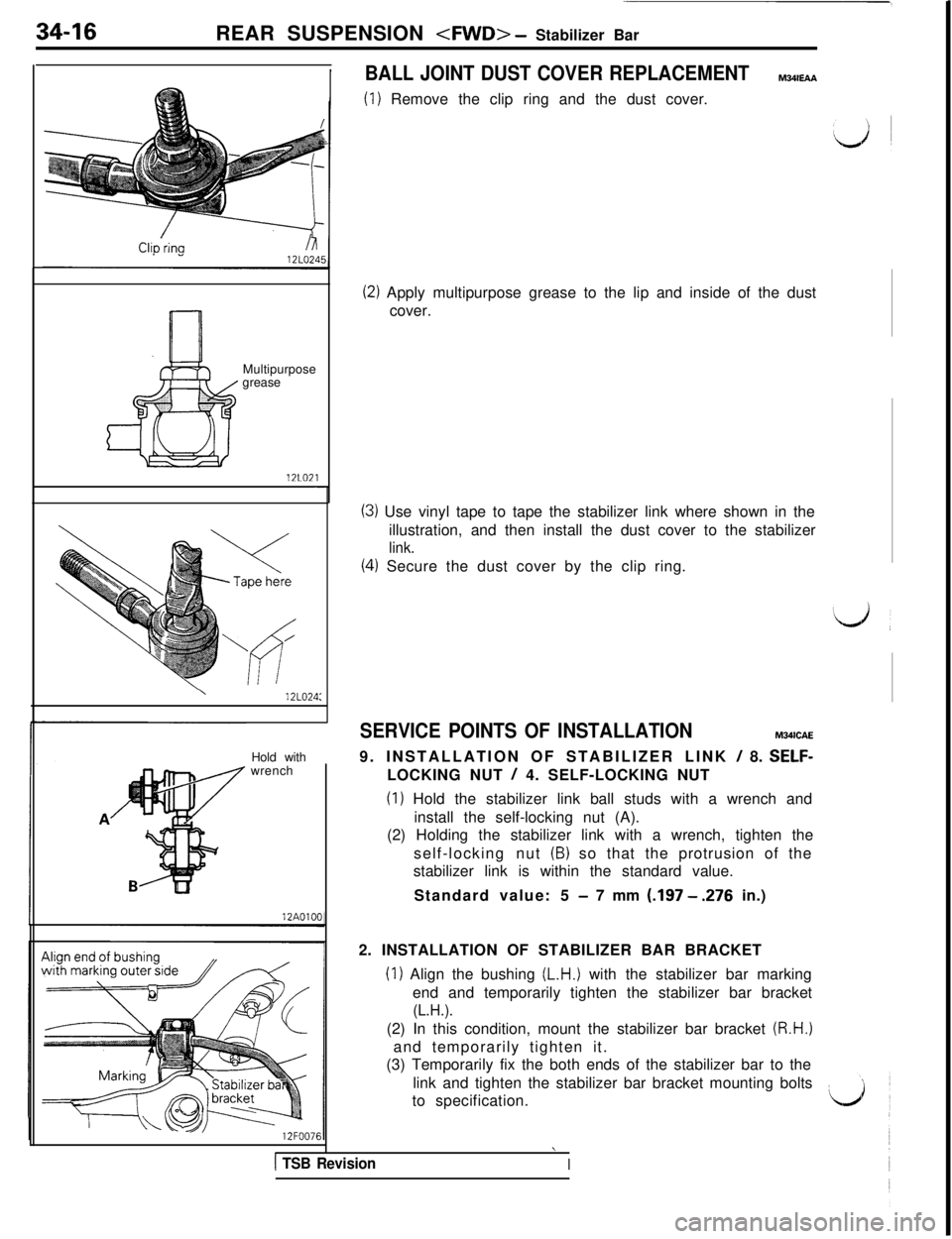
BALL JOINT DUST COVER REPLACEMENTMWEAA
(1) Remove the clip ring and the dust cover.
(2) Apply multipurpose grease to the lip and inside of the dust
cover.
(3) Use vinyl tape to tape the stabilizer link where shown in the
illustration, and then install the dust cover to the stabilizer
link.
(4) Secure the dust cover by the clip ring.
SERVICE POINTS OF INSTALLATIONM341CAE
9. INSTALLATION OF STABILIZER LINK
/ 8. SELF-LOCKING NUT
/ 4. SELF-LOCKING NUT
(I) Hold the stabilizer link ball studs with a wrench and
install the self-locking nut (A).
(2) Holding the stabilizer link with a wrench, tighten the
self-locking nut
(B) so that the protrusion of the
stabilizer link is within the standard value.
Standard value: 5
- 7 mm (197 - .276 in.)
2. INSTALLATION OF STABILIZER BAR BRACKET
(1) Align the bushing (L.H.) with the stabilizer bar marking
end and temporarily tighten the stabilizer bar bracket
(L.H.).(2) In this condition, mount the stabilizer bar bracket
(R.H.)and temporarily tighten it.
(3) Temporarily fix the both ends of the stabilizer bar to the
link and tighten the stabilizer bar bracket mounting bolts
to specification.
1 TSB Revision
\
I
Page 703 of 1146
REAR SUSPENSION
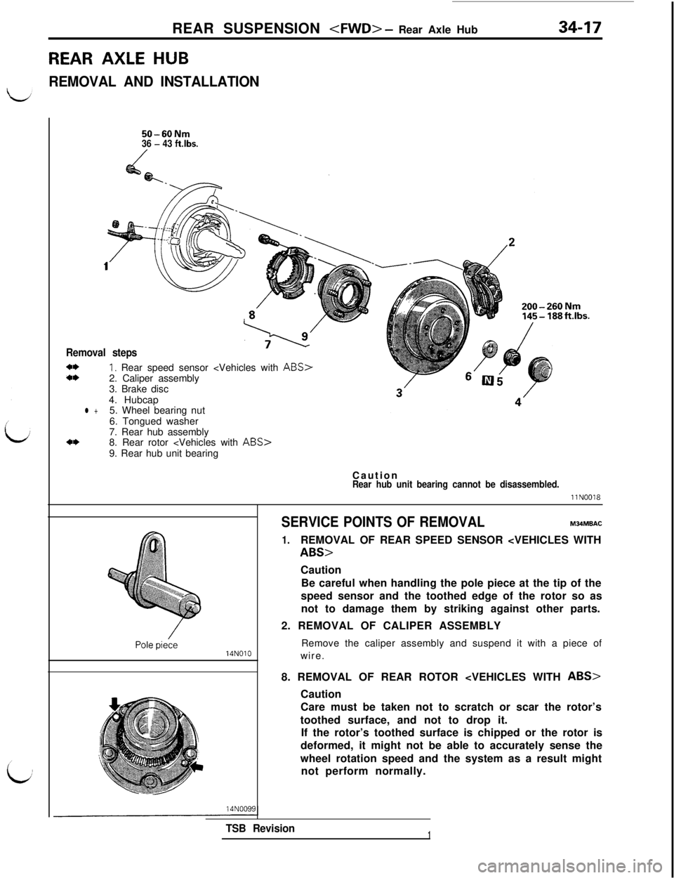
REAR AXLE HUB34-17
REMOVAL AND INSTALLATION
50-60Nm36 - 43 ftlbs.
1
Removal steps
*I)I, Rear speed sensor
3. Brake disc
4. Hubcap
l +5. Wheel bearing nut
6. Tongued washer
7. Rear hub assembly
*I)8. Rear rotor
Caution
Rear hub unit bearing cannot be disassembled.
llN0018
14NOlO14N009E
SERVICE POINTS OF REMOVALM34MBAC
1.REMOVAL OF REAR SPEED SENSOR
Be careful when handling the pole piece at the tip of the
speed sensor and the toothed edge of the rotor so as
not to damage them by striking against other parts.
2. REMOVAL OF CALIPER ASSEMBLY
Remove the caliper assembly and suspend it with a piece of
wire.
8. REMOVAL OF REAR ROTOR
Care must be taken not to scratch or scar the rotor’s
toothed surface, and not to drop it.
If the rotor’s toothed surface is chipped or the rotor is
deformed, it might not be able to accurately sense the
wheel rotation speed and the system as a result might
not perform normally.
TSB Revision1
Page 704 of 1146
34-18
REAR SUSPENSION
Spindle
_’ ,14NOOOt
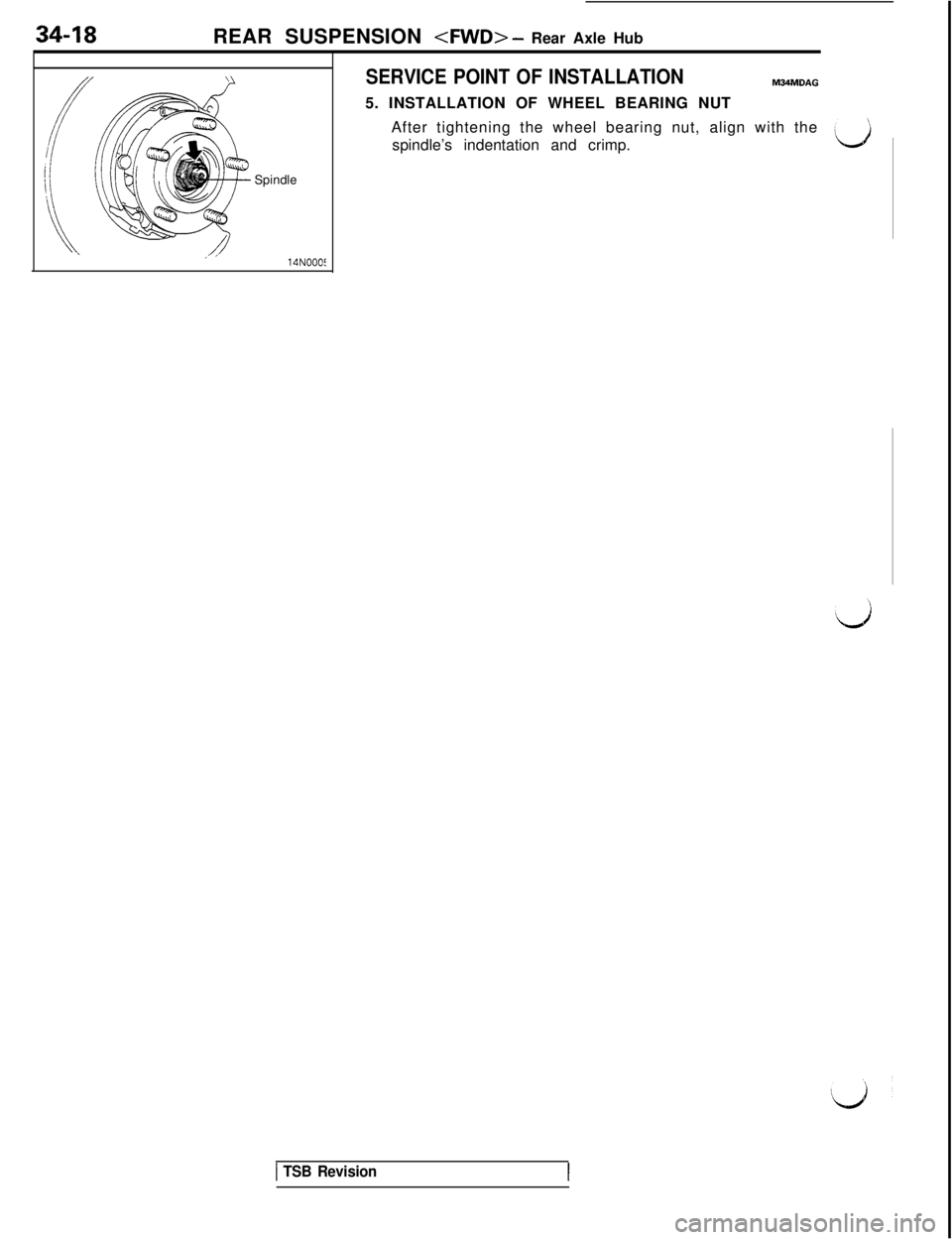
SERVICE POINT OF INSTALLATIONM34MDAG5. INSTALLATION OF WHEEL BEARING NUT
After tightening the wheel bearing nut, align with the
spindle’s indentation and crimp.
\a
1 TSB Revision
Page 705 of 1146
REAR SUSPENSION
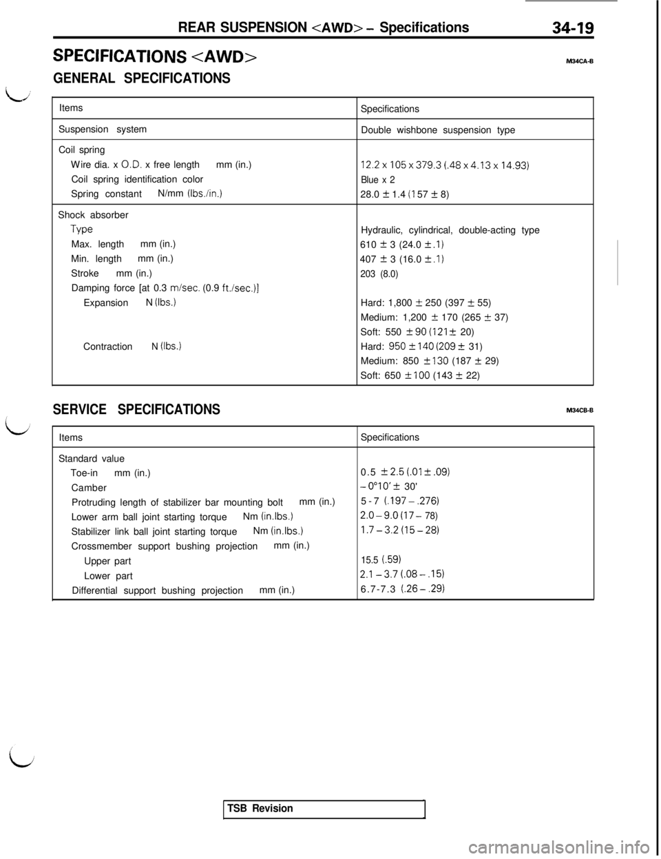
SPECIFICATIONS
GENERAL SPECIFICATIONS34-19M34CA-B
Items
Suspension system
Coil spring
Wire dia. x O.D. x free lengthmm (in.)
Coil spring identification color
Spring constantN/mm
(Ibs./in.)Shock absorberType
Max. lengthmm (in.)
Min. lengthmm (in.)
Strokemm (in.)
Damping force [at 0.3 misec. (0.9
ft./set.)]ExpansionN
(Ibs.)Contraction
N (Ibs.)Specifications
Double wishbone suspension type
12.2x105x379.3(.48x4.13x14.93)
Blue x 228.0
2 1.4 (I 57 -t 8)
Hydraulic, cylindrical, double-acting type
610
2 3 (24.0 f .I)407
f 3 (16.0 2 .I)
203 (8.0)Hard: 1,800
+ 250 (397 +- 55)
Medium: 1,200
rtr 170 (265 t 37)
Soft: 550
f 90(121 + 20)
Hard:
950? 140 (209 t 31)
Medium: 850
2 130 (187 + 29)
Soft: 650
f 100 (143 2 22)
SERVICE SPECIFICATIONSM34CB-B
ItemsSpecifications
Standard value
Toe-inmm (in.)0.5
k 2.5(.01 f .09)Camber
-0”lO’ Ifr 30'
Protruding length of stabilizer bar mounting boltmm (in.)5-7
(.197-,276)Lower arm ball joint starting torqueNm (in.lbs.)
2.0-9.0(17 - 78)Stabilizer link ball joint starting torqueNm
(inlbs.)1.7-3.2(15-28)Crossmember support bushing projectionmm (in.)
Upper part
15.5 (.59)Lower part
2.1-3.7(.08-.15)Differential support bushing projectionmm (in.)6.7-7.3
(.26-.29)
TSB Revision
Page 706 of 1146
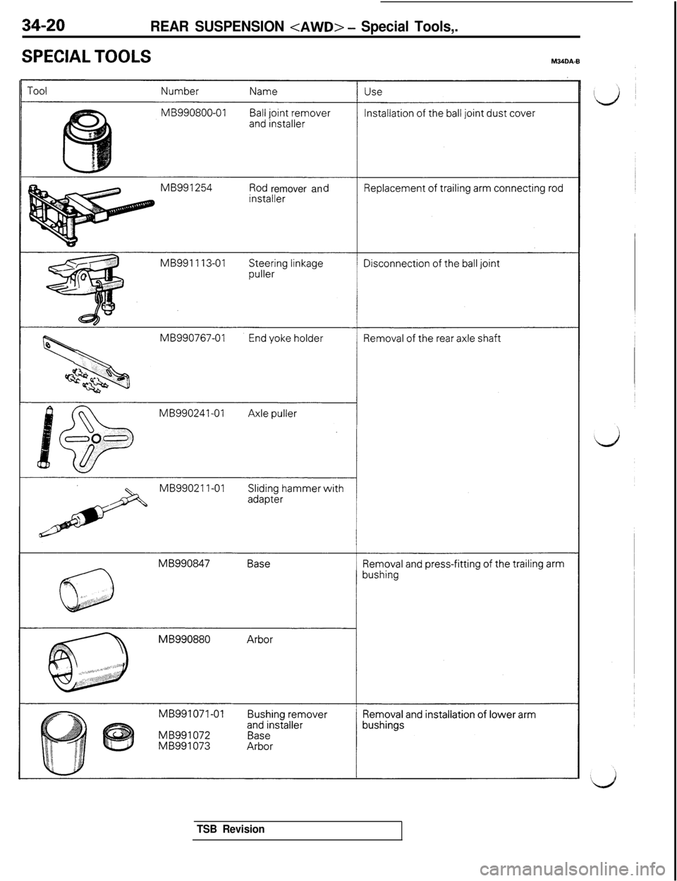
34-20REAR SUSPENSION
SPECIAL TOOLSM34DA.Bremover anMB990241-01
TSB Revision
Page 707 of 1146
REAR SUSPENSION
I’
id
TSB Revision
Page 708 of 1146
34-22REAR SUSPENSION
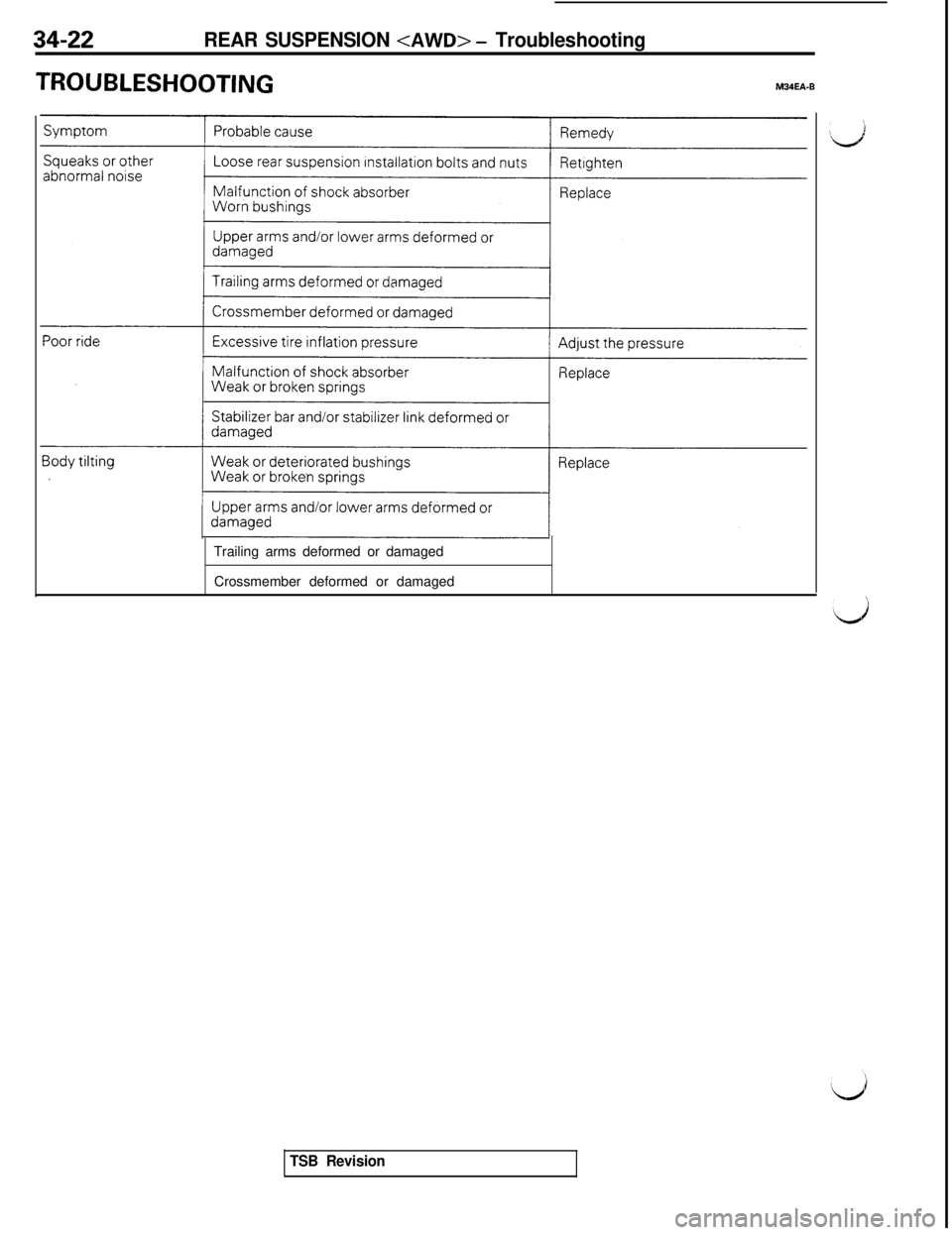
TROUBLESHOOTINGM34EA-B
Trailing arms deformed or damaged
Crossmember deformed or damaged
TSB Revision
Page 709 of 1146
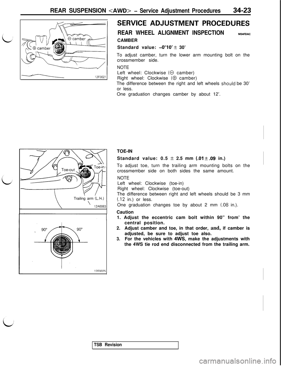
REAR SUSPENSION
SERVICE ADJUSTMENT PROCEDURES
REAR WHEEL ALIGNMENT INSPECTIONM34FDACCAMBER
Standard value:
-0”lO’ + 30’
To adjust camber, turn the lower arm mounting bolt on the
crossmember side.
NOTE
12FOO21Left wheel: Clockwise (0 camber)
Right wheel: Clockwise
(0 camber)
The difference between the right and left wheels
shoiuld be 30’
or less.
One graduation changes camber by about 12’.
\Trailing arm (L.H.)
\\12A0083
17FllO75TOE-IN
Standard value: 0.5
-t 2.5 mm (.Ol + .09 in.)
To adjust toe, turn the trailing arm mounting bolts on the
crossmember side on both sides the same amount.
NOTELeft wheel: Clockwise (toe-in)
Right wheel: Clockwise (toe-out)
The difference between right and left wheels should be 3 mm
(.12 in.) or less.
One graduation changes toe by about 2 mm
(.08 in.).
Caution
1. Adjust the eccentric cam bolt within 90” from’ the
central position.
2.Adjust camber and toe, in that order, and, if camber is
adjusted, be sure to adjust toe also.
3.For the vehicles with 4WS, make the adjustments with
the 4WS tie rod end disconnected from the trailing arm.
TSB Revision
Page 710 of 1146
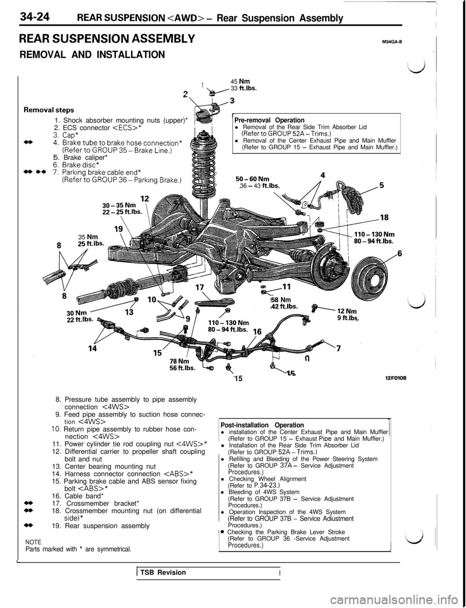
34-24REAR SUSPENSION
REAR SUSPENSION ASSEMBLY
REMOVAL AND INSTALLATION
M34GA-B
L
Rel
145 Nm9- 33 ftlbs.
1. Shock absorber mounting nuts (upper)*
2. ECS connector
(RefertoGROUP52A-Trims.)l Removal of the Center Exhaust Pipe and Main Muffler
(Refer to GROUP 15
- Exhaust Pipe and Main Muffler.)
5. Brake caliper*
1,50-60NmI36 - 43 ft.lbs.35 Nm
$8 Nm“?C,ILc. ashwez I,..“=.BP’----12Nm9 ftlbs.
15..e12FO1088. Pressure tube assembly to pipe assembly
connection
<4WS>9. Feed pipe assembly to suction hose connec-
tion
<4WS>10. Return pipe assembly to rubber hose con-
nection t4WS>11. Power cylinder tie rod coupling nut <4WS>*12. Differential carrier to propeller shaft coupling
bolt and nut
Post-installation Operationl installation of the Center Exhaust Pipe and Main Muffler
(Refer to GROUP 15
- Exhaust Pioe and Main Muffler.)
l Installation of the Rear Side Trim Absorber Lid
(Refer to GROUP
52A-Trims.)13. Center bearing mounting nut
14. Harness connector connection
CABS>*15. Parking brake cable and ABS sensor fixingl Refilling and Bleeding of the Power Steering System
(Refer to GROUP
37A- Service AdjustmentProcedures.)bolt
17. Crossmember bracket*
18. Crossmember mounting nut (on differential
side)”19. Rear suspension assemblyl Checking Wheel Alignment
(Refer to P.34-23.)
l Bleeding of 4WS System
(Refer to GROUP 37B
- Service Adjustment
Procedures.)
l Operation Inspection of the 4WS System
(Refer to GROUP 37B - Service AdiustmentProcedures.)
NOTEParts marked with * are symmetrical.
,* Checking the Parking Brake Lever Stroke
(Refer to GROUP 36 -Service Adjustment
Procedures.)i
1 TSB RevisionI