MITSUBISHI 3000GT 1991 Service Manual
Manufacturer: MITSUBISHI, Model Year: 1991, Model line: 3000GT, Model: MITSUBISHI 3000GT 1991Pages: 1146, PDF Size: 76.68 MB
Page 801 of 1146
SERVICE BRAKES - Front Disc Brake
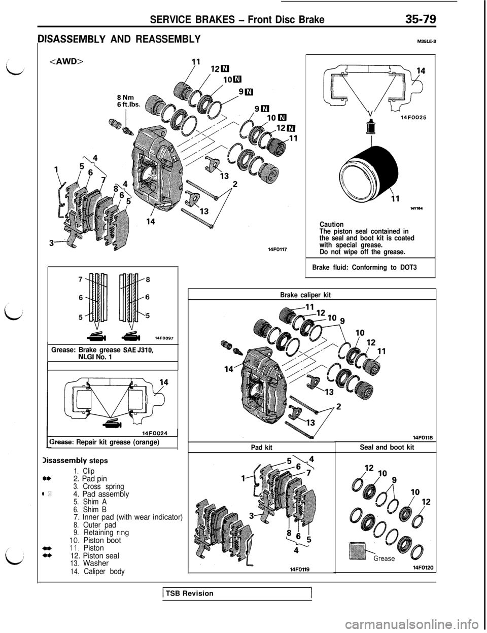
IISASSEMBLY AND REASSEMBLY
8
66
55
Grease: Brake grease SAE 5310,NLGI No. 1
14FOQ24
St-ease: Repair kit grease (orange)
Xsassembly steps
1.Clip*I)2. Pad pin3.Cross springl *4. Pad assembly5.Shim A6.Shim B7. Inner pad (with wear indicator)8.Outer pad9.Retainingnng
10.Piston boot*I)11.Piston*I)12. Piston seal13.Washer
14.Caliper body
14FO117
MJSLE-8V
f
14FOO25
Caution
The piston seal contained in
the seal and boot kit is coated
with special grease.
Do not wipe off the grease.
Brake fluid: Conforming to DOT3
Brake caliper kit
14FO118
Pad kitSeal and boot kit14FOll9
14FO120
,1 TSB Revision
Page 802 of 1146
35-80SERVICE BRAKES - Front Disc Brake14FOOl14FOO4
14FOO2:
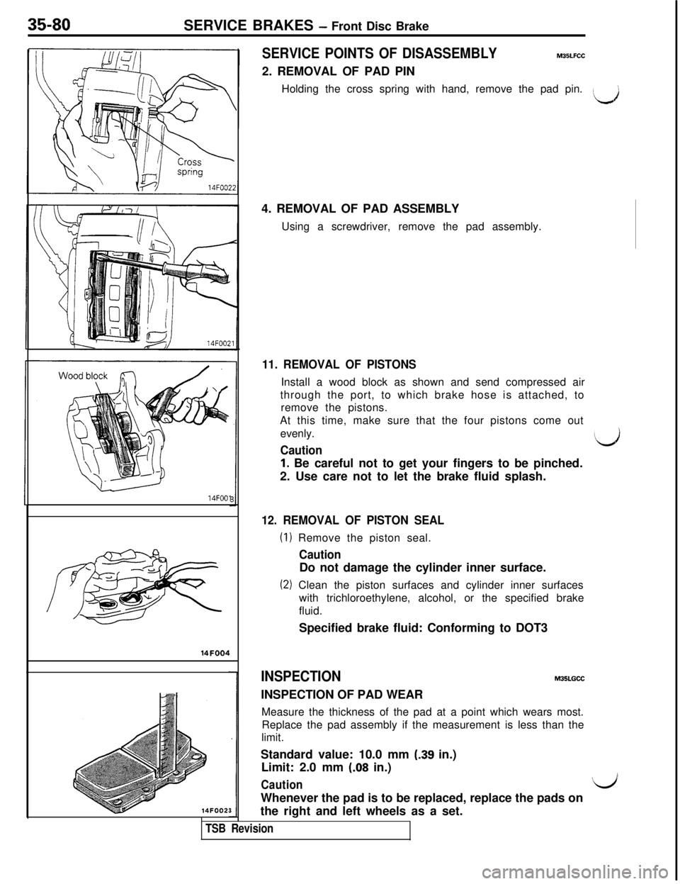
SERVICE POINTS OF DISASSEMBLYM35LFCC2. REMOVAL OF PAD PIN
Holding the cross spring with hand, remove the pad pin.
4. REMOVAL OF PAD ASSEMBLY
Using a screwdriver, remove the pad assembly.
11. REMOVAL OF PISTONSInstall a wood block as shown and send compressed air
through the port, to which brake hose is attached, to
remove the pistons.
At this time, make sure that the four pistons come out
evenly.
Caution
1. Be careful not to get your fingers to be pinched.
2. Use care not to let the brake fluid splash.
‘d
12. REMOVAL OF PISTON SEAL
(1) Remove the piston seal.
CautionDo not damage the cylinder inner surface.
(2) Clean the piston surfaces and cylinder inner surfaces
with trichloroethylene, alcohol, or the specified brake
fluid.
Specified brake fluid: Conforming to DOT3
INSPECTIONMJSLGCCINSPECTION OF PAD WEAR
Measure the thickness of the pad at a point which wears most.
Replace the pad assembly if the measurement is less than the
limit.
Standard value: 10.0 mm
(.39 in.)
Limit: 2.0 mm
(.08 in.)
CautionI/’Whenever the pad is to be replaced, replace the pads on
the right and left wheels as a set.
TSB Revision
Page 803 of 1146

SERVICE BRAKES - Rear Disc Brake35-81
REAR DISC BRAKE
/REMOVAL AND INSTALLATION
i
(Refer to P.35-48.1
50-60Nm36 - 43 ft.lbs.3
Removal steps
I. Brake hose~4 2. Rear brake assembly3. Brake disc
50-60Nm36 - 43 ftlbs.
M35MA- -
Flared brake line nuts
15 Nm
11 ft.lbs.
INSPECTION
INSPECTING THE BRAKE DISCl Check disc for wear. (Refer to
P.35-55.)l Check disc for runout. (Refer to
P.35-55.)l Check disc for damage.
M35MDAC
SERVICE POINT OF INSTALLATIONM35MCAG2. INSTALLATION OF THE REAR BRAKE ASSEMBLY
Install the rear brake assembly using the same procedure
as that for the front brake assembly. (Refer to
P.35-74.)TSB Revision
Page 804 of 1146
35-82SERVICE BRAKES - Rear Disc Brake
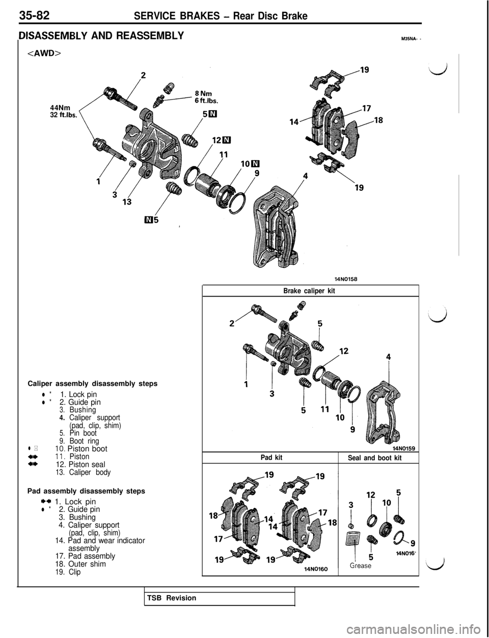
USASSEMBLY AND REASSEMBLYM35NA- -
32 ft.lbs.Caliper assembly disassembly steps
l *1. Lock pinl *2. Guide pin3.Bushing
4.Caliper support
(pad, clip, shim)
5.Pin boot9.Boot ringl *10. Piston boot4*11.Pistona*12. Piston seal13.Caliper bodyPad assembly disassembly steps
*+ 1. Lock pinl *2. Guide pin
3. Bushing
4. Caliper support
(pad, clip, shim)14. Pad and wear indicator
assembly
17. Pad assembly
18. Outer shim
19. Clip
,1814NOl58
Brake caliper kit
Pad kit
Seal and boot kit14N0160
TSB Revision
Page 805 of 1146
SERVICE BRAKES - Rear Disc Brake35-83
:FWD>
27 Nm20 ft.lbs.
6
Illi ’I13
-
11"?"L
pi,
d $A,, :;y,
44 4% w403.57
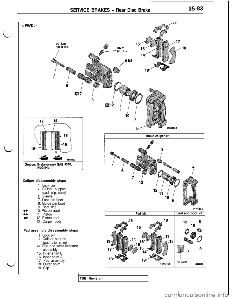
Grease: Br3rt;ty SAE J310,Caliper disassembly steps
1.Lock pin4.Caliper support
(pad, clip, shim)
6.Sleeve7. Lock pin boot
8. Guide pin boot
9.Boot ring*I)10. Piston boot*I)11.Piston*+12. Piston seal13.Caliper bodyPad assembly disassembly steps
1. Lock pin
4. Caliper support
(pad, clip, shim)14. Pad and wear indicator
assembly
15. Inner shim B
16. Inner shim A
17. Pad assembly18. Outer shim
19. Clip
w
19".*:a;*4~. ,/'.*"+:-r
48Nm&&----6ft.lbs.18I”,
Brake caliper kit
Pad kit
155
Seal and boot kit
18
14N0156Grease14N015TSB Revision
Page 806 of 1146
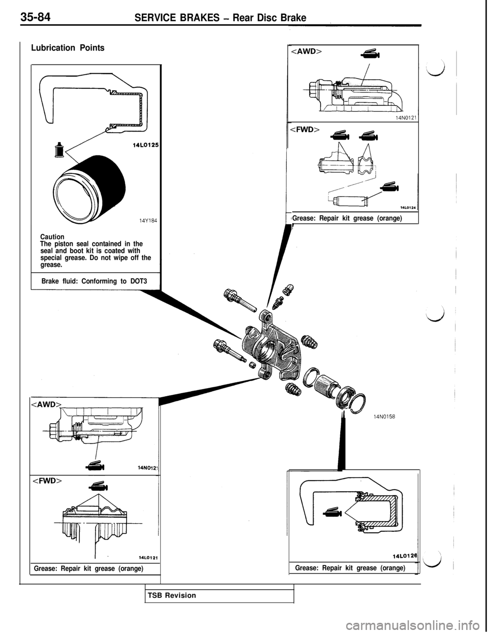
35-84SERVICE BRAKES - Rear Disc Brake
Lubrication Points14Y184
Caution
The piston seal contained in the
seal and boot kit is coated with
special grease. Do not wipe off the
grease.
Brake fluid: Conforming to DOT3
Grease: Repair kit grease (orange)
t14N0121
14LO12,
Grease: Repair kit grease (orange)
I-14NO158
Grease: Repair kit grease (orange)14LO128
TSB Revision
Page 807 of 1146
SERVICE BRAKES - Rear Disc Brake35-85
i
id14N0131
i
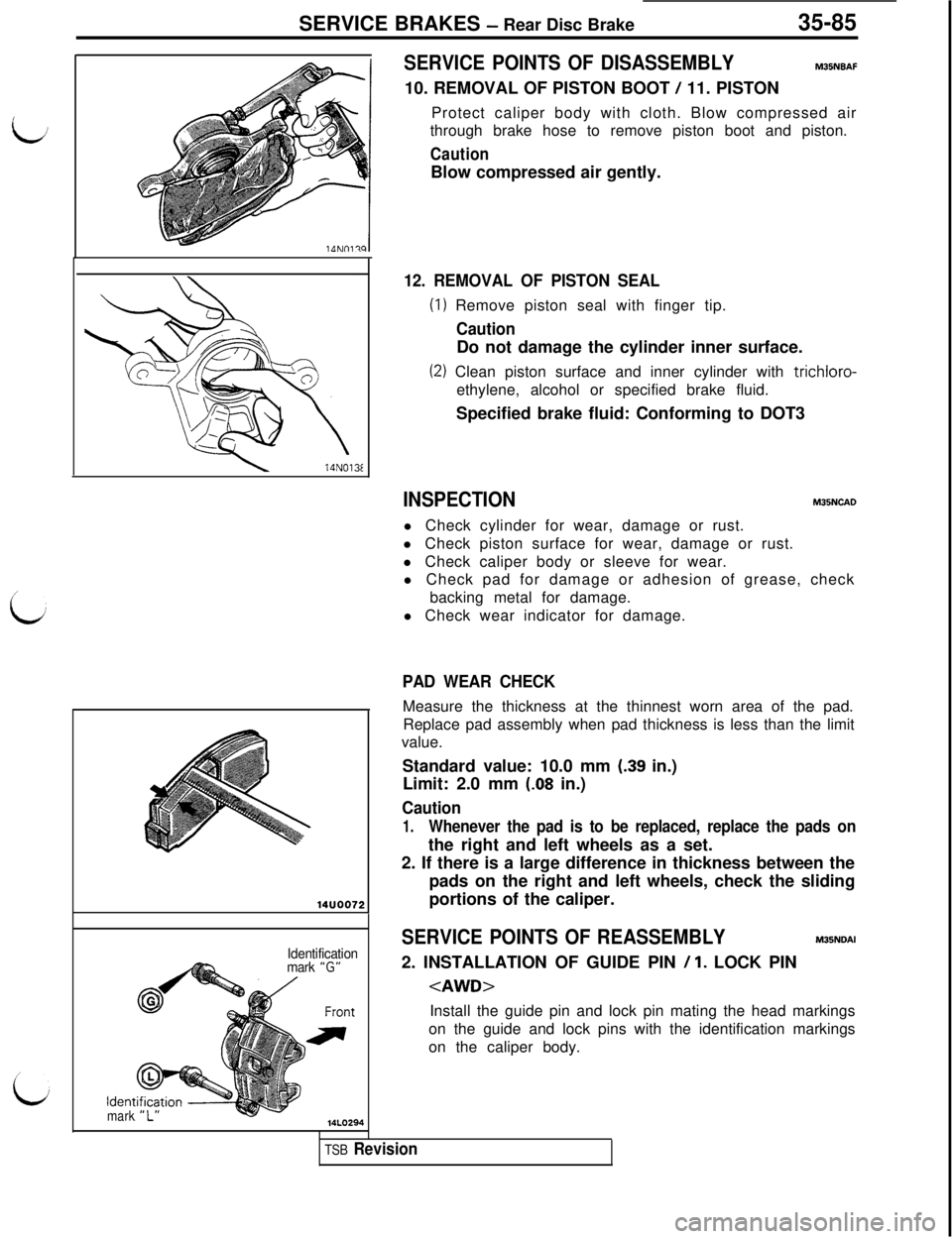
SERVICE POINTS OF DISASSEMBLYM35NBAF10. REMOVAL OF PISTON BOOT
/ 11. PISTON
Protect caliper body with cloth. Blow compressed air
through brake hose to remove piston boot and piston.
CautionBlow compressed air gently.
12. REMOVAL OF PISTON SEAL
(I) Remove piston seal with finger tip.
CautionDo not damage the cylinder inner surface.
(2) Clean piston surface and inner cylinder with trichloro-
ethylene, alcohol or specified brake fluid.
Specified brake fluid: Conforming to DOT3
INSPECTIONM35NCAOl Check cylinder for wear, damage or rust.
l Check piston surface for wear, damage or rust.
l Check caliper body or sleeve for wear.
l Check pad for damage or adhesion of grease, check
backing metal for damage.
l Check wear indicator for damage.
PAD WEAR CHECKMeasure the thickness at the thinnest worn area of the pad.
Replace pad assembly when pad thickness is less than the limit
value.
Standard value: 10.0 mm
(39 in.)
Limit: 2.0 mm
(.08 in.)
Caution
1.Whenever the pad is to be replaced, replace the pads onthe right and left wheels as a set.
2. If there is a large difference in thickness between the
pads on the right and left wheels, check the sliding
portions of the caliper.
Identification
mark “G”
ldentmark
SERVICE POINTS OF REASSEMBLYM35NOAI2. INSTALLATION OF GUIDE PIN
/ 1. LOCK PIN
on the guide and lock pins with the identification markings
on the caliper body.
TSB Revision
Page 808 of 1146
35-86SERVICE BRAKES - Hydraulic Unit (ABS)HYDRAULIC UNIT (ABS)
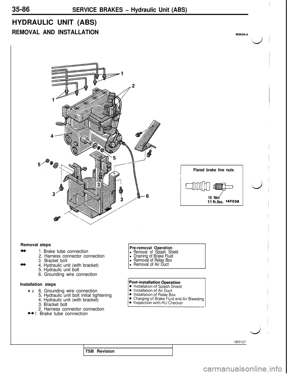
REMOVAL AND INSTALLATION
I
M350A.ARemoval steps
4*1. Brake tube connection
2. Harness connector connection
3.Bracketbolt4*4. Hydraulic unit (with bracket)
5. Hydraulic unit bolt
6. Grounding wire connection
1Flared brake line nuts
/15 Nmllftlbs. 14FO33
Pre-removal Operationl Removal of Splash Shieldl Draining of Brake Fluidl Removal of Relay Boxl Removal of Air DuctInstallation steps
l a6. Grounding wire connection
5. Hydraulic unit bolt initial tightening
4. Hydraulic unit (with bracket)
3. Bracket bolt
2. Harness connector connection
** 1. Brake tube connection19FO127
TSB Revision
Page 809 of 1146
SERVICE BRAKES - Hvdraulic Unit (ABS)35-87
14FOO8:
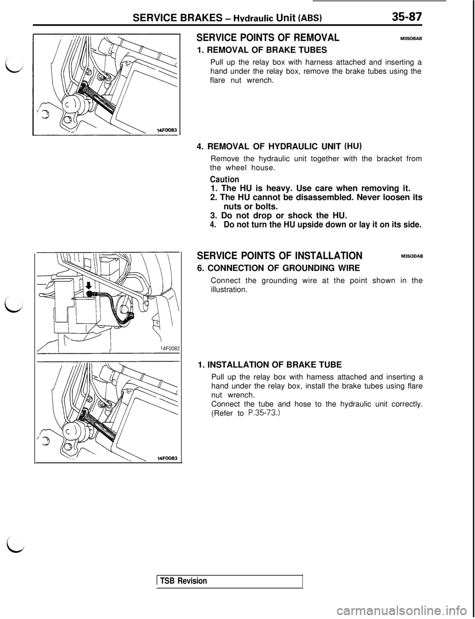
SERVICE POINTS OF REMOVALM350BAB1. REMOVAL OF BRAKE TUBES
Pull up the relay box with harness attached and inserting a
hand under the relay box, remove the brake tubes using the
flare nut wrench.
4. REMOVAL OF HYDRAULIC UNIT
(HU)Remove the hydraulic unit together with the bracket from
the wheel house.
Caution1. The HU is heavy. Use care when removing it.
2. The HU cannot be disassembled. Never loosen its
nuts or bolts.
3. Do not drop or shock the HU.
4.Do not turn the HU upside down or lay it on its side.
SERVICE POINTS OF INSTALLATIONM350DAB6. CONNECTION OF GROUNDING WIRE
Connect the grounding wire at the point shown in the
illustration.
1. INSTALLATION OF BRAKE TUBE
Pull up the relay box with harness attached and inserting a
hand under the relay box, install the brake tubes using flare
nut wrench.
Connect the tube and hose to the hydraulic unit correctly.
(Refer to
P.35-73.)
c
1 TSB Revision
Page 810 of 1146
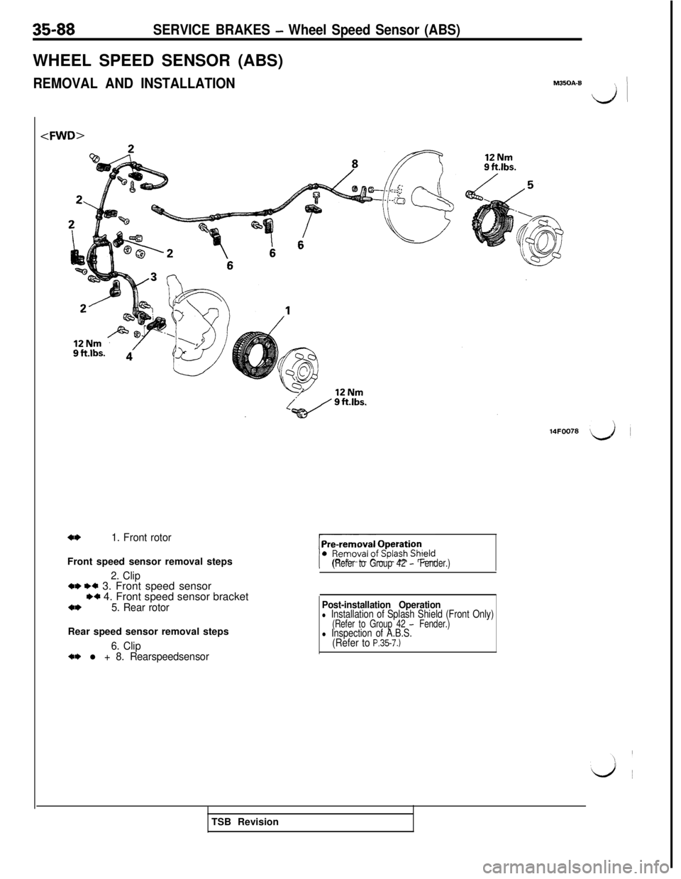
3588SERVICE BRAKES - Wheel Speed Sensor (ABS)WHEEL SPEED SENSOR (ABS)
REMOVAL AND INSTALLATION
a*1. Front rotorFront speed sensor removal steps
2. Clip*I) ++ 3. Front speed sensorw 4. Front speed sensor bracket*I)5. Rear rotorRear speed sensor removal steps
6. Clipa* l + 8. Rearspeedsensor
M350A-B L/ 1
(Refer to Group 42 - Fender.)
14FOO78LJ
Post-installation Operationl Installation of Splash Shield (Front Only)(Refer to Group 42 - Fender.)l Inspection of A.B.S.(Refer to P.35-7.)TSB Revision