MITSUBISHI 3000GT 1991 Service Manual
3000GT 1991
MITSUBISHI
MITSUBISHI
https://www.carmanualsonline.info/img/19/57085/w960_57085-0.png
MITSUBISHI 3000GT 1991 Service Manual
Trending: jump cable, oil filter, seats, clock reset, lock, window, brakes
Page 791 of 1146
SERVICE BRAKES - Master Cylinder and Brake Booster35-69light
scale14AO471
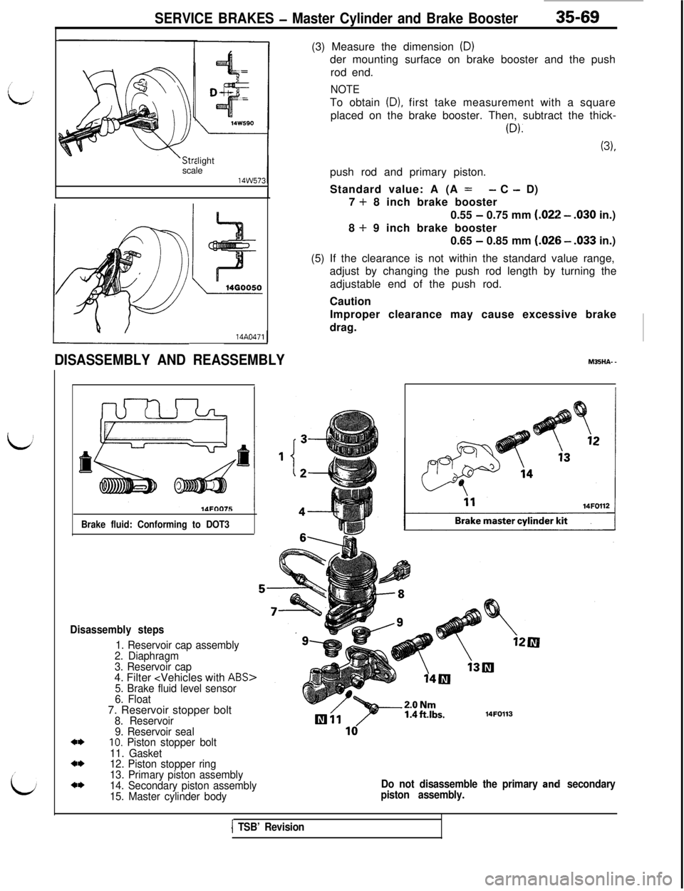
DISASSEMBLY AND REASSEMBLY
Brake fluid: Conforming to DOT3
Disassembly steps
1. Reservoir cap assembly
2. Diaphragm
3. Reservoir cap4. Filter
5. Brake fluid level sensor
6. Float7. Reservoir stopper bolt
8. Reservoir
9. Reservoir seal
*I)IO. Piston stopper bolt
11. Gasket
a*12. Piston stopper ring
13. Primary piston assembly
a*14. Secondary piston assembly
15. Master cylinder body(3) Measure the dimension
(D)der mounting surface on brake booster and the push
rod end.
NOTETo obtain
(D), first take measurement with a square
placed on the brake booster. Then, subtract the thick-
(D).
(3),push rod and primary piston.
Standard value: A (A
=- C - D)
7
+ 8 inch brake booster
0.55
- 0.75 mm (.022 - .030 in.)
8
+ 9 inch brake booster
0.65
- 0.85 mm (.026 - .033 in.)
(5) If the clearance is not within the standard value range,
adjust by changing the push rod length by turning the
adjustable end of the push rod.
Caution
Improper clearance may cause excessive brake
drag.M35HA-
-
14FOll3
Do not disassemble the primary ancH secondary
piston assembly.
1 TSB’ Revision
Page 792 of 1146
35-70SERVICE BRAKES - Master Cylinder and Brake Booster
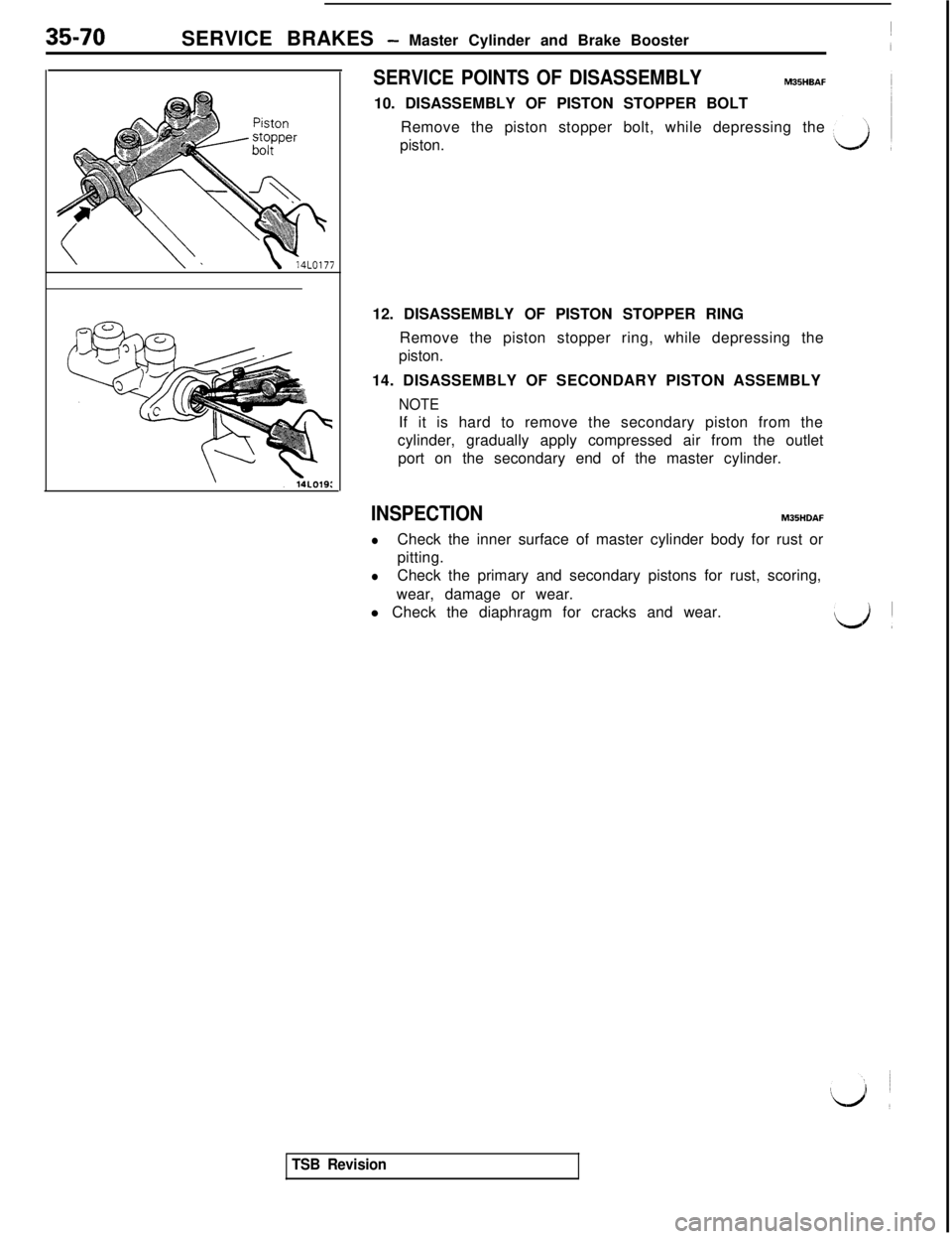
SERVICE POINTS OF DISASSEMBLYMBSHBAF10. DISASSEMBLY OF PISTON STOPPER BOLT
Remove the piston stopper bolt, while depressing the
piston.
12. DISASSEMBLY OF PISTON STOPPER RING
Remove the piston stopper ring, while depressing the
piston.
14. DISASSEMBLY OF SECONDARY PISTON ASSEMBLY
NOTEIf it is hard to remove the secondary piston from the
cylinder, gradually apply compressed air from the outlet
port on the secondary end of the master cylinder.
INSPECTIONM35HDAF
lCheck the inner surface of master cylinder body for rust or
pitting.
lCheck the primary and secondary pistons for rust, scoring,
wear, damage or wear.
l Check the diaphragm for cracks and wear.
‘.‘d I
TSB Revision
Page 793 of 1146
SERVICE BRAKES - Brake Line
BRAKE LINE
REMOVAL AND INSTALLATION35-71
M35uA. -
ABS>
Pre-removal Operationl Draining of Brake Fluid
Post-installation Operationl Supplying Brake Fluid
l Bleeding (Refer to P.35-48.)
Flared brake line nuts
15 Nm
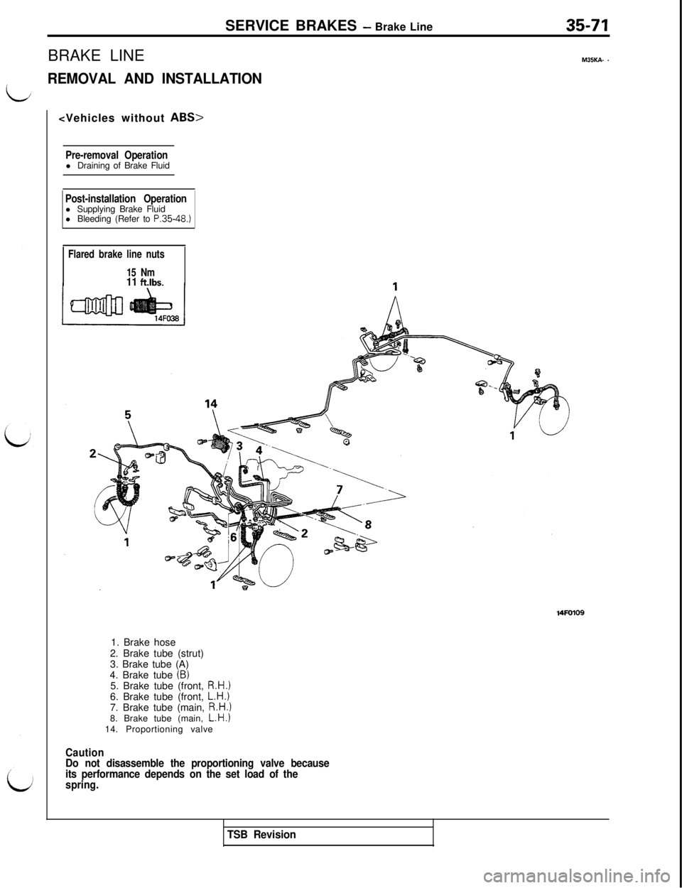
11 ft.lbs.1. Brake hose
2. Brake tube (strut)
3. Brake tube (A)
4. Brake tube
(B)5. Brake tube (front, R.H.)6. Brake tube (front, L.H.)7. Brake tube (main, R.H.)8. Brake tube (main, L.H.)14. Proportioning valve
Caution
Do not disassemble the proportioning valve because
its performance depends on the set load of the
spring.
TSB Revision
Page 794 of 1146
35-72SERVICE BRAKES - Brake Line
ABS>
IFlared brake line nutsI15Nm
11 ft.lbs.
1 AFO38
Cormecting part ofhvdraulic wnit
54
12
113
614FOOlS
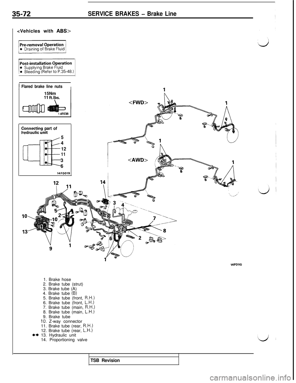
,1. Brake hose
2. Brake tube (strut)
3. Brake tube (A)
4. Brake tube
(B)5. Brake tube (front, R.H.)6. Brake tube (front, L.H.)7. Brake tube (main, R.H.)8. Brake tube (main, L.H.)9. Brake tube
10. Z-way connector
11. Brake tube (rear, R.H.)12. Brake tube (rear, L.H.)O+ 13. Hydraulic unit
14. Proportioning valve
TSB Revision
Page 795 of 1146
SERVICE BRAKES - Brake Line / Front Disc Brake35-73 (1’
‘6
14FOO20
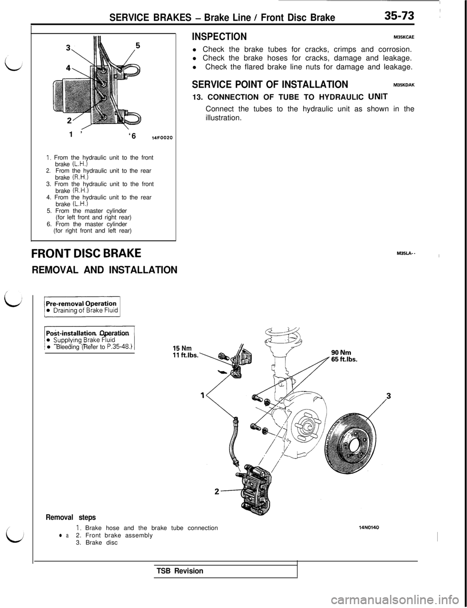
1. From the hydraulic unit to the front
brake (L.H.)2.From the hydraulic unit to the rear
brake (R.H.)3. From the hydraulic unit to the front
brake
(R.H.)4. From the hydraulic unit to the rear
brake
(L.H.)5. From the master cylinder
(for left front and right rear)
6. From the master cylinder
(for right front and left rear)
INSPECTIONMPBKCAEl Check the brake tubes for cracks, crimps and corrosion.
l Check the brake hoses for cracks, damage and leakage.
lCheck the flared brake line nuts for damage and leakage.
SERVICE POINT OF INSTALLATIONMOBKDAK13. CONNECTION OF TUBE TO HYDRAULIC
UNIITConnect the tubes to the hydraulic unit as shown in the
illustration.
FRONT DISC BRAKE
REMOVAL AND INSTALLATIONM35LA-.
I
Pod-installation Operationl Bleeding (Refer to
P.35-48.)
::Nmft.lbs.
Removal steps
I, Brake hose and the brake tube connection14N0140
l a2. Front brake assembly
3. Brake discI
TSB Revision
Page 796 of 1146
35-74
SERVICE BRAKES - Front Disc Brake
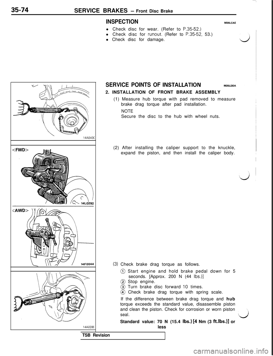
INSPECTIONM35LCAEl Check disc for wear. (Refer to
P.35-52.)l Check disc for runout. (Refer to
P.35-52, 53.)Il Check disc for damage.14A040C
(2) After installing the caliper support to the knuckle,
expand the piston, and then install the caliper body.
(3) Check brake drag torque as follows.@ Start engine and hold brake pedal down for 5
seconds. [Approx. 200 N (44
Ibs.)]@ Stop engine.@ Turn brake disc forward
10 times.@ Check brake drag torque with spring scale.
If the difference between brake drag torque and hub
torque exceeds the standard value, disassemble piston
and clean the piston. Check for corrosion or worn piston
\\
seal.l/iStandard value: 70 N (15.4 Ibs.)
[4 Nm (3 ft.lbs.)l or14A033E
less
SERVICE POINTS OF lNS?ALLATlONM35LDDA2. INSTALLATION OF FRONT BRAKE ASSEMBLY
(1) Measure hub torque with pad removed to measure
brake drag torque after pad installation.
NOTESecure the disc to the hub with wheel nuts.
TSB Revision
Page 797 of 1146
SERVICE BRAKES - Front Disc Brake35-75
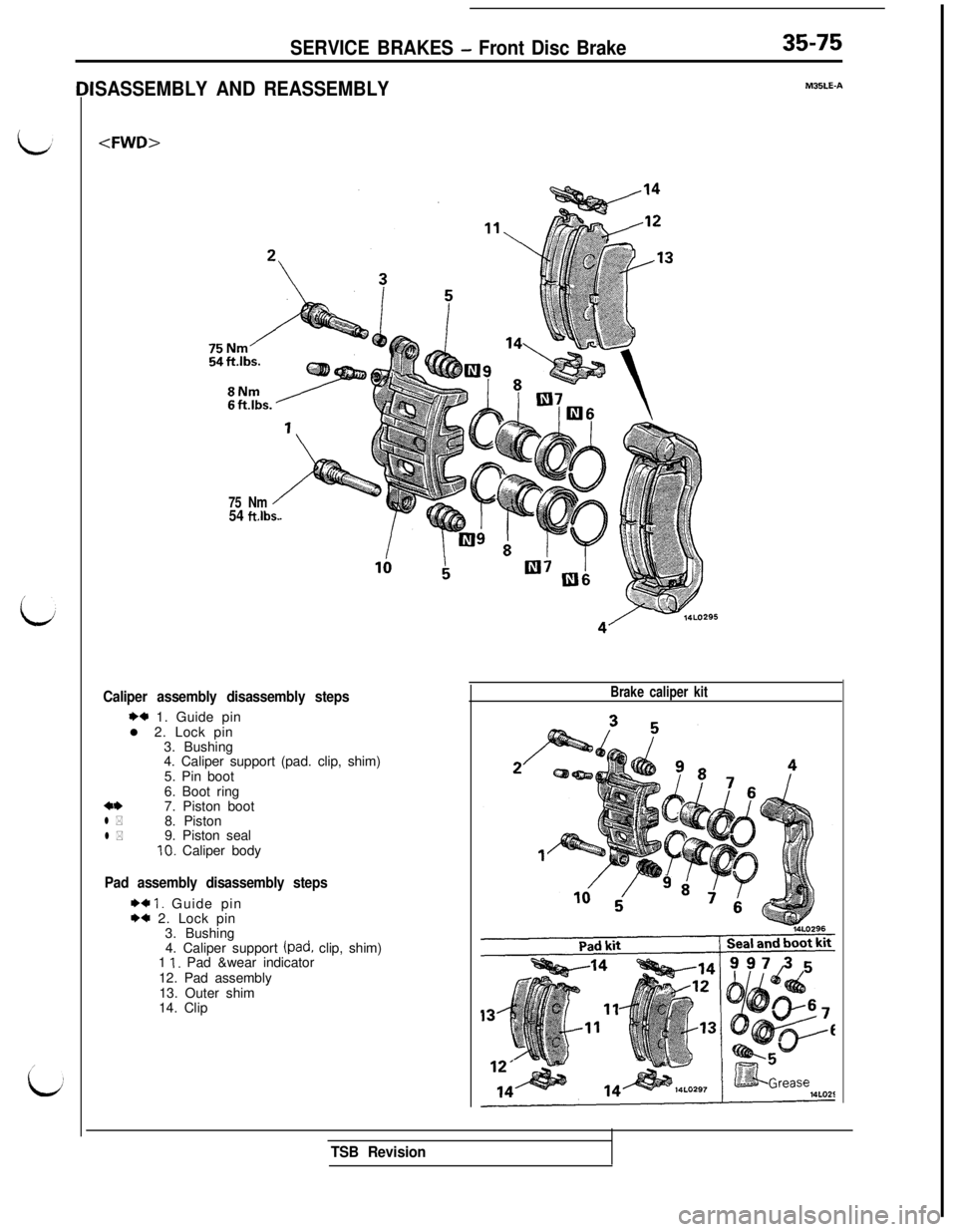
SASSEMBLY AND REASSEMBLYM35LE-A
Caliper assembly disassembly steps
1)* 1. Guide pin
l 2. Lock pin
3. Bushing
4. Caliper support (pad. clip, shim)
5. Pin boot
6. Boot ring
7. Piston boot
8. Piston
9. Piston sealIO. Caliper body
a*l *
l *
Pad assembly disassembly steps
I)+ I. Guide pinw 2. Lock pin
3. Bushing
4. Caliper support
(pad, clip, shim)
1 I. Pad &wear indicator
12. Pad assembly
13. Outer shim
14. Clip
75 Nm54 ftlbs.
Brake caliper kit
TSB Revision
Page 798 of 1146
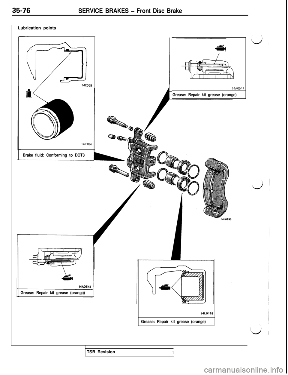
35-76SERVICE BRAKES - Front Disc BrakeLubrication points
!14KO6914Y184
-
ai
Brake fluid: Conforming to DOT3
Grease: Repair kit grease (orange)14A0541
Grease: Repair kit grease (orange)
14LO128
Grease: Repair kit grease (orange)TSB Revision
1
Page 799 of 1146
SERVICE BRAKES - Front Disc Brake35-77
14AO553
14AO55114uoo7i
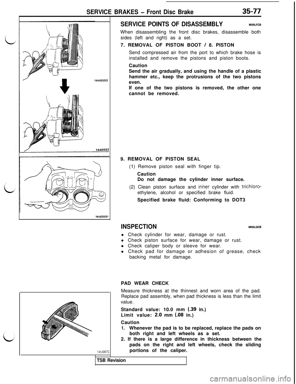
SERVICE POINTS OF DISASSEMBLYM35LFCB
When disassembling the front disc brakes, disassemble both
sides (left and right) as a set.
7. REMOVAL OF PISTON BOOT
/ 8. PISTON
Send compressed air from the port to which brake hose is
installed and remove the pistons and piston boots.
Caution
Send the air gradually, and using the handle of a plastic
hammer etc., keep the protrusions of the two pistons
even.
If one of the two pistons is removed, the other one
cannot be removed.
9. REMOVAL OF PISTON SEAL
(1) Remove piston seal with finger tip.
Caution
Do not damage the cylinder inner surface.
(2) Clean piston surface and inher cylinder with trichloro-
ethylene, alcohol or specified brake fluid.
Specified brake fluid: Conforming to DOT3
INSPECTIONMOBLGCBl Check cylinder for wear, damage or rust.
l Check piston surface for wear, damage or rust.
l Check caliper body or sleeve for wear.
l Check pad for damage or adhesion of grease, check
backing metal for damage.
PAD WEAR CHECK
Measure thickness at the thinnest and worn area of the pad.
Replace pad assembly, when pad thickness is less than the limit
value.
Standard value: 10.0 mm (.39 in.)
Limit value: 2.0 mm
(08 in.)
Caution
1.Whenever the pad is to be replaced, replace the pads on
both right and left wheels as a set.
2. If there is a large difference in thickness between the
pads on the right and left wheels, check the sliding
portions of the caliper.
TSB Revision
Page 800 of 1146
SERVICE BRAKES - Front Disc Brake
ldenti
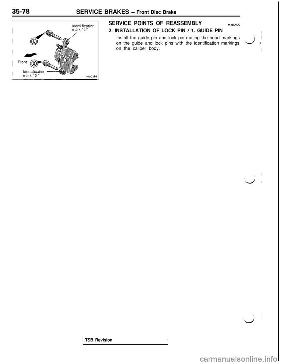
ficationSERVICE POINTS OF REASSEMBLYM35LHCC2. INSTALLATION OF LOCK PIN
/ 1. GUIDE PINIInstall the guide pin and lock pin mating the head markings
‘I ~
on the guide and lock pins with the identification markings
LJ i
on the caliper body.
I
1 TSB Revision1
Trending: coolant reservoir, wheel bolt torque, air bleeding, gas mileage, automatic transmission fluid, transmission fluid, length

