MITSUBISHI 3000GT 1991 Service Manual
Manufacturer: MITSUBISHI, Model Year: 1991, Model line: 3000GT, Model: MITSUBISHI 3000GT 1991Pages: 1146, PDF Size: 76.68 MB
Page 771 of 1146
SERVICE BRAKES - Service Adiustment Procedures
i14LO29C
1Al 0781
14LO291141029
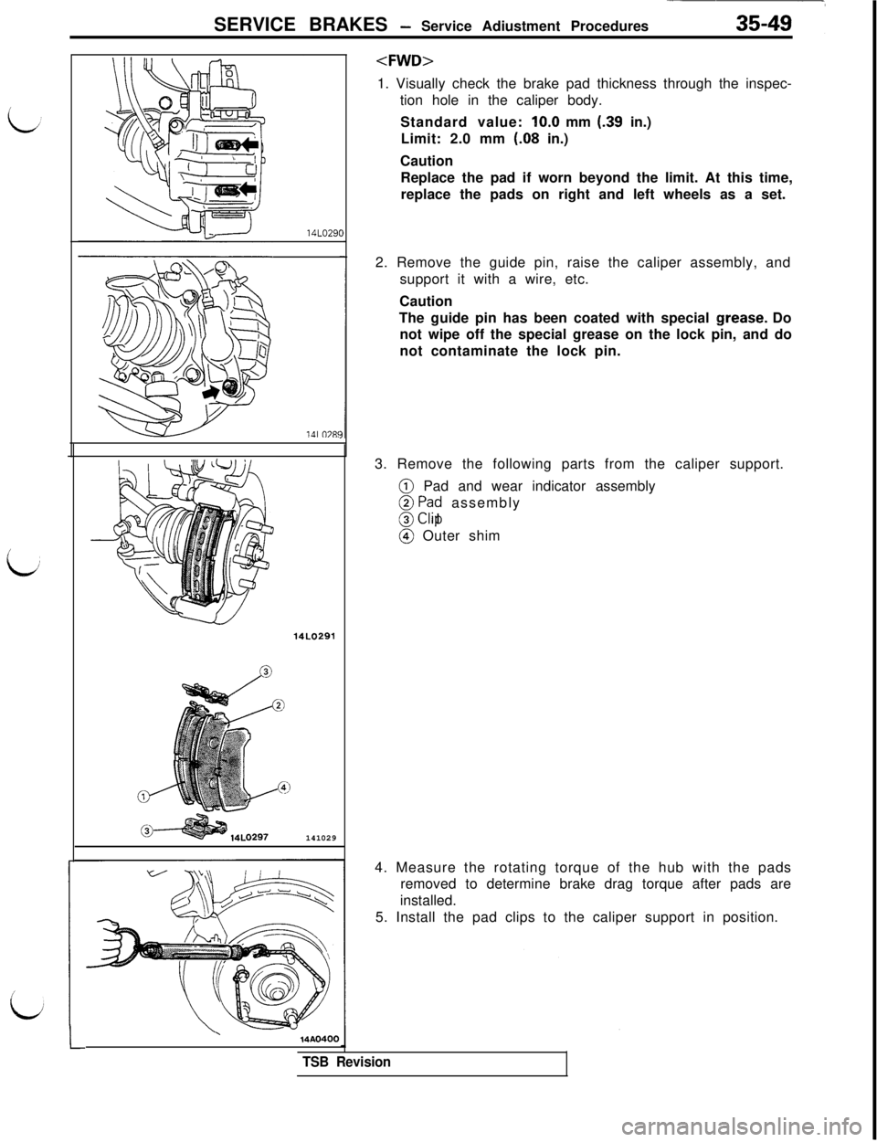
tion hole in the caliper body.
Standard value: IO.0 mm
(.39 in.)
Limit: 2.0 mm (.08 in.)
Caution
Replace the pad if worn beyond the limit. At this time,
replace the pads on right and left wheels as a set.
2. Remove the guide pin, raise the caliper assembly, and
support it with a wire, etc.
Caution
The guide pin has been coated with special
Igrease. Do
not wipe off the special grease on the lock pin, and do
not contaminate the lock pin.
3. Remove the following parts from the caliper support.@ Pad and wear indicator assembly
8 F$$ assembly
3 I@ Outer shim
4. Measure the rotating torque of the hub with the pads
removed to determine brake drag torque after pads are
installed.
5. Install the pad clips to the caliper support in position.
\14AO400
TSB Revision
Page 772 of 1146
35-50SERVICE BRAKES - Service Adjustment Procedures
Pad pin
1 AFnn97
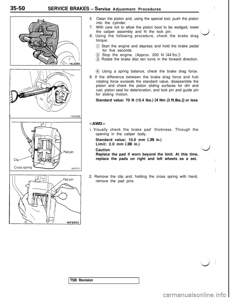
6.Clean the piston and, using the special tool, push the piston
into the cylinder.
7.With care not to allow the piston boot to be wedged, lower
the caliper assembly and fit the lock pin.
8. Using the following procedure, check the brake drag
‘d ,
torque.@ Start the engine and depress and hold the brake pedal
for five seconds.@ Stop the engine. (Approx. 200 N
[44 Ibs.])@ Rotate the brake disc ten turns in the forward direction.@ Using a spring balance, check the brake drag force.
9. If the difference between the brake drag force and hub
rotating force exceeds the standard value, disassemble the
piston and check the piston sliding surfaces for dirt and
rust, piston seal for deterioration, and lock pin and guide pin
for sliding motion.
Standard value: 70 N (15.4 Ibs.)
[4 Nm (3 ftlbs.)] or less
opening in the caliper body.
Standard value: 10.0 mm
(-39 in.)
Limit: 2.0 mm
(.08 in.)
Caution
‘L&iReplace the pad if worn beyond the limit. At this time,
replace the pads on right and left wheels as a set.
I2. Remove the clip and, holding the cross spring with hand,
remove the pad pins.
TSB Revision
Page 773 of 1146
SERVICE BRAKES - Service Adjustment Procedures35-51
iPad assembly
Shim A
Shim B
3‘IShim B
Shim A
14FOO9i.
_-TSB RevisionGrease
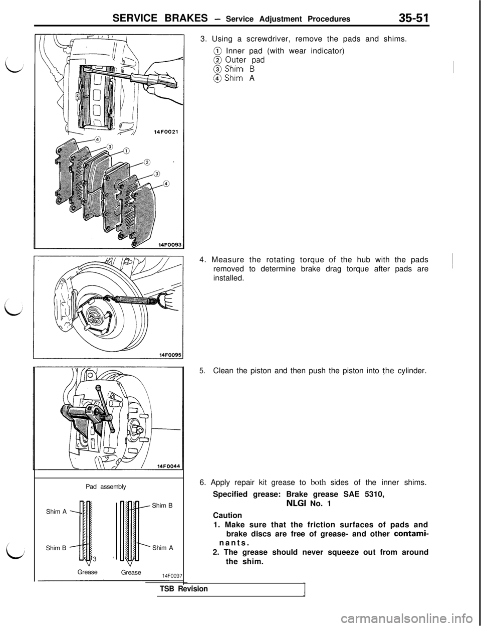
Grease3. Using a screwdriver, remove the pads and shims.
@ Inner pad (with wear indicator)
8 C$+r ;ad
(iJ Sh:: A
4. Measure the rotating torque
qf the hub with the pads
removed to determine brake drag torque after pads are~
installed.
5.Clean the piston and then push the piston into the cylinder.
6. Apply repair kit grease to both sides of the inner shims.
Specified grease: Brake grease SAE 5310,NLGI No. 1
Caution
1. Make sure that the friction surfaces of pads and
brake discs are free of grease- and other
contami-nants.
2. The grease should never squeeze out from around
the shim.
Page 774 of 1146
35-52SERVICE BRAKES - Service Adjustment Procedures
14FOO94
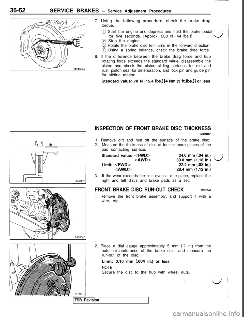
k.!! I14FOO427. Using the following procedure, check the brake drag
torque.@ Start the engine and depress and hold the brake pedal
’for five seconds. [Approx. 200 N (44
Ibs.)]@ Stop the engine.@ Rotate the brake disc ten turns in the forward direction.@ Using a spring balance, check the brake drag force.
8. If the difference between the brake drag force and hub
rotating force exceeds the standard value, disassemble the
piston and check the piston sliding surfaces for dirt and
rust, piston seal for deterioration, and lock pin and guide pin
for sliding motion.
Standard value: 70 N (15.4
Ibs.) [4 Nm (3 ft.lbs.)] or less
INSPECTION OF FRONT BRAKE DISC THICKNESS1. Remove dirt and rust off the surface of the brake disc.
2.Measure the thickness of disc at four or more places of the
pad contacting surface.
Standard value:
,Limit:
3.If the wear exceeds the limit even at one place, replace the
right and left discs and brake pads as a set.
FRONT BRAKE DISC RUN-OUT CHECKM35FSAF
1. Remove the front brake assembly; and support it with a
wire, etc.
TSB Revision2. Place a dial gauge approximately 5 mm
(.2 in.) from the
outer circumference of the brake disc, and measure the
run-out of the disc.
Limit: 0.10 mm (.004 in.) or less
NOTESecure the disc to the hub with wheel nuts.
Page 775 of 1146
L.
SERVICE BRAKES -Service Adjustment Procedures35-53
I14A0398
14F003r
i14A04014NOO27
7
FRONT BRAKE DISC RUN-OUT CORRECTION
M35FFAC
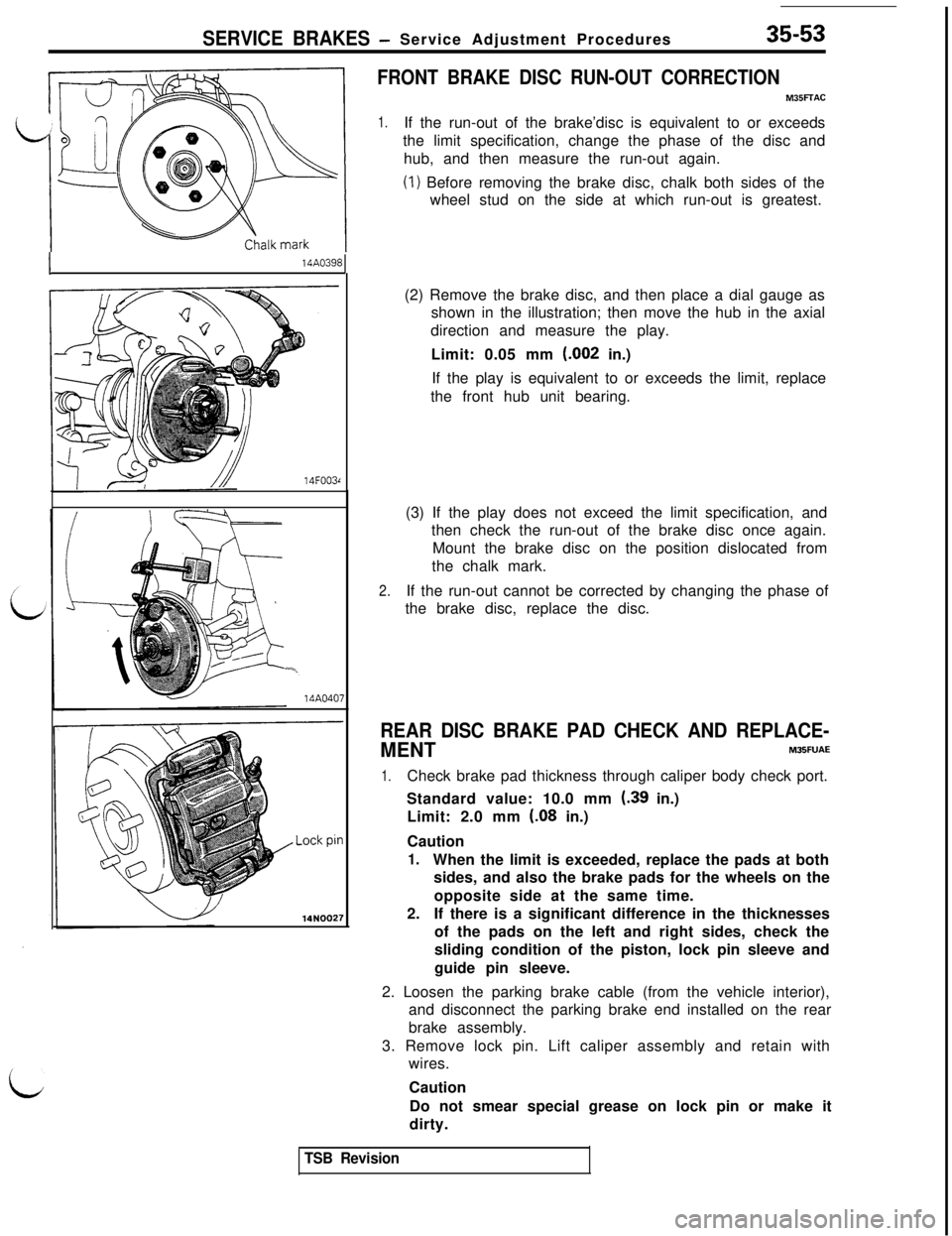
1.If the run-out of the brake’disc is equivalent to or exceeds
the limit specification, change the phase of the disc and
hub, and then measure the run-out again.
(1) Before removing the brake disc, chalk both sides of the
wheel stud on the side at which run-out is greatest.
(2) Remove the brake disc, and then place a dial gauge as
shown in the illustration; then move the hub in the axial
direction and measure the play.
Limit: 0.05 mm (.002 in.)
If the play is equivalent to or exceeds the limit, replace
the front hub unit bearing.
(3) If the play does not exceed the limit specification, and
then check the run-out of the brake disc once again.
Mount the brake disc on the position dislocated from
the chalk mark.
2.If the run-out cannot be corrected by changing the phase of
the brake disc, replace the disc.
REAR DISC BRAKE PAD CHECK AND REPLACE-
MENTM35FUAE
1.Check brake pad thickness through caliper body check port.
Standard value: 10.0 mm
(39 in.)
Limit: 2.0 mm
(08 in.)
Caution
1.When the limit is exceeded, replace the pads at both
sides, and also the brake pads for the wheels on the
opposite side at the same time.
2.If there is a significant difference in the thicknesses
of the pads on the left and right sides, check the
sliding condition of the piston, lock pin sleeve and
guide pin sleeve.
2. Loosen the parking brake cable (from the vehicle interior),
and disconnect the parking brake end installed on the rear
brake assembly.
3. Remove lock pin. Lift caliper assembly and retain with
wires.
Caution
Do not smear special grease on lock pin or make it
dirty.
TSB Revision
Page 776 of 1146
SERVICE BRAKES - Service Adjustment Procedures
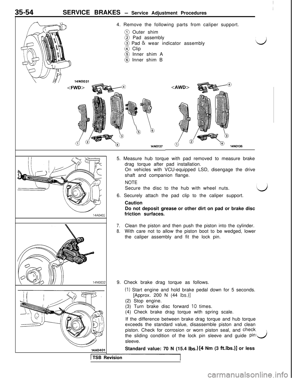
4. Remove the following parts from caliper support.@ Outer shim@ Pad assembly@ Pad & wear indicator assembly@ Clip@ Inner shim A@ Inner shim B
d
14N0031
/0014N013714A040;14N003:
14AO401
l%FLision
14N01365. Measure hub torque with pad removed to measure brake
drag torque after pad installation.
On vehicles with VCU-equipped LSD, disengage the drive
shaft and companion flange.
NOTESecure the disc to the hub with wheel nuts.
6. Securely attach the pad clip to the caliper support.
Caution
Do not deposit
&ease or other dirt on pad or brake disc
friction surfaces.
7.Clean the piston and then push the piston into the cylinder.
8.With care not to allow the piston boot to be wedged, lower
the caliper assembly and fit the lock pin.
9. Check brake drag torque as follows.
(I) Start engine and hold brake pedal down for 5 seconds.
[Approx. 200 N (44
Ibs.)](2) Stop engine.
(3) Turn brake disc forward
10 times.
(4) Check brake drag torque with spring scale.
If the difference between brake drag torque and hub torque
exceeds the standard value, disassemble piston and clean
piston. Check for corrosion or worn piston seal, andcheck
the sliding condition of the lock pin sleeve and guide
pinl/jsleeve.
Standard value: 70 N (15.4
Ibs,,) [4 Nm (3 ft.lbs.)] or less
Page 777 of 1146
![MITSUBISHI 3000GT 1991 Service Manual SERVICE BRAKES - Service Adjustment Procedures35-5514N0171
\\ \ \14NOO98]
14A04013
REAR BRAKE DISC THICKNESS CHECKM35FVA.D1. Remove dirt and rust from brake disc surface.
2. Measure disc thickness at MITSUBISHI 3000GT 1991 Service Manual SERVICE BRAKES - Service Adjustment Procedures35-5514N0171
\\ \ \14NOO98]
14A04013
REAR BRAKE DISC THICKNESS CHECKM35FVA.D1. Remove dirt and rust from brake disc surface.
2. Measure disc thickness at](/img/19/57085/w960_57085-776.png)
SERVICE BRAKES - Service Adjustment Procedures35-5514N0171
\\ \ \14NOO98]
14A04013
REAR BRAKE DISC THICKNESS CHECKM35FVA.D1. Remove dirt and rust from brake disc surface.
2. Measure disc thickness at 4 locations or more.
Standard value:
Limit:
Replace the discs and pad assembly for both sides left and
right of the vehicle if they are worn beyond the specified
limit.
REAR BRAKE DISC RUN-OUT CHECKM35FWAC
1.Remove the rear brake assembly, and support it by a wire,
etc.
2. Place a dial gauge approximately 5 mm
(.2 in.) from the
outer circumference of the brake disc, and measure the
run-out of the disc.
Limit: 0.08 mm
(.0031 in.) or less
NOTETighten nuts to secure the disc to the hub.
REAR BRAKE DISC RUN-OUT CORRECTIONM35FXAB
1.If the run-out of the brake disc is equivalent to or exceeds
the limit specification, change the phase of the disc and
hub, and then measure the run-out again.
NOTEThe procedures for checking by changing the installation
phase of the disc are the same as those for the front brake
discs. Note, however, that the axial play (limit) in the hub
differs. (Refer to
P.35-53.)Limit:
2.If the problem cannot be corrected by changing the phase
of the brake disc, replace the disc.
1 TSB Revision
Page 778 of 1146
35-56SERVICE BRAKES - Service Adjustment Proceduresi
14N0179
\14N008Ei
BRAKE LINING THICKNESS CHECKM35FIAD
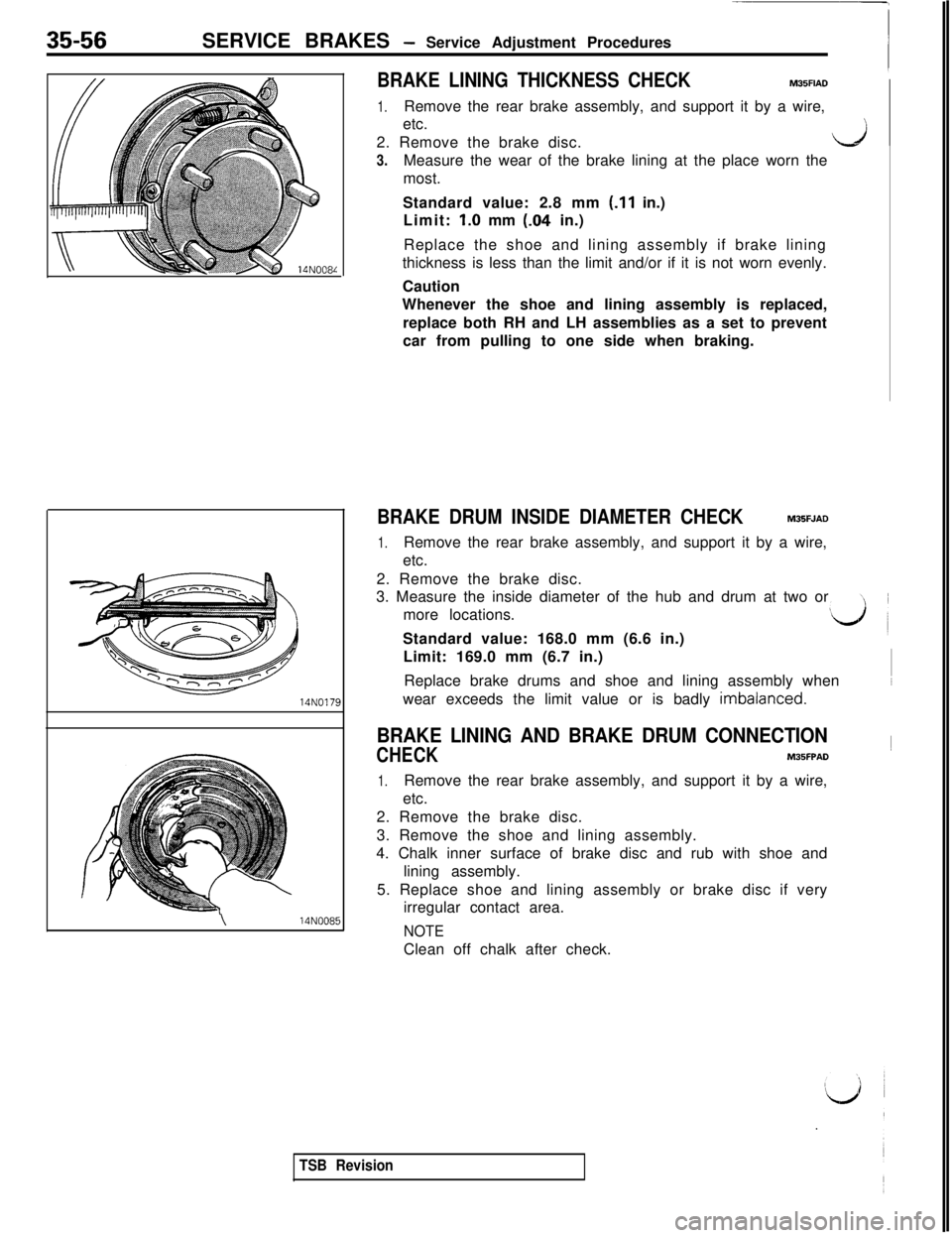
1.Remove the rear brake assembly, and support it by a wire,
etc.
2. Remove the brake disc.
3.
L?jMeasure the wear of the brake lining at the place worn the
most.
Standard value: 2.8 mm
(.I1 in.)
Limit:
1.0 mm (-04 in.)
Replace the shoe and lining assembly if brake lining
thickness is less than the limit and/or if it is not worn evenly.
Caution
Whenever the shoe and lining assembly is replaced,
replace both RH and LH assemblies as a set to prevent
car from pulling to one side when braking.
BRAKE DRUM INSIDE DIAMETER CHECKM35FJAD
1.Remove the rear brake assembly, and support it by a wire,
etc.
2. Remove the brake disc.
3. Measure the inside diameter of the hub and drum at two or
more locations.
Standard value: 168.0 mm (6.6 in.)
Limit: 169.0 mm (6.7 in.)
Replace brake drums and shoe and lining assembly when~~
wear exceeds the limit value or is badly imbalanced.
BRAKE LINING AND BRAKE DRUM CONNECTION
CHECK~M35FPAD
1.Remove the rear brake assembly, and support it by a wire,
etc.
2. Remove the brake disc.
3. Remove the shoe and lining assembly.
4. Chalk inner surface of brake disc and rub with shoe and
lining assembly.
5. Replace shoe and lining assembly or brake disc if very
irregular contact area.
NOTEClean off chalk after check.
TSB Revision
Page 779 of 1146
SERVICE BRAKES - Service Adjustment Procedures35-57
i
~18~17~16~15~14~13~12~11~10~ 9 18 I 7 16 I 5 14 13 12 1 1 1[35~34~33~32~31~30~29~28~27~26~25~24~23~22~21~20~19~Check connector
ECU
/m/Body harness
MB991 35614N018(
I I I 2When turned manually
~---~---~-.-~---[--.I 1MEASUREMENT OF
WHEEL SPEED SENSOR
OUTPUT VOLTAGEM35FOAO
1. Lift up the vehicle and release the parking brake.
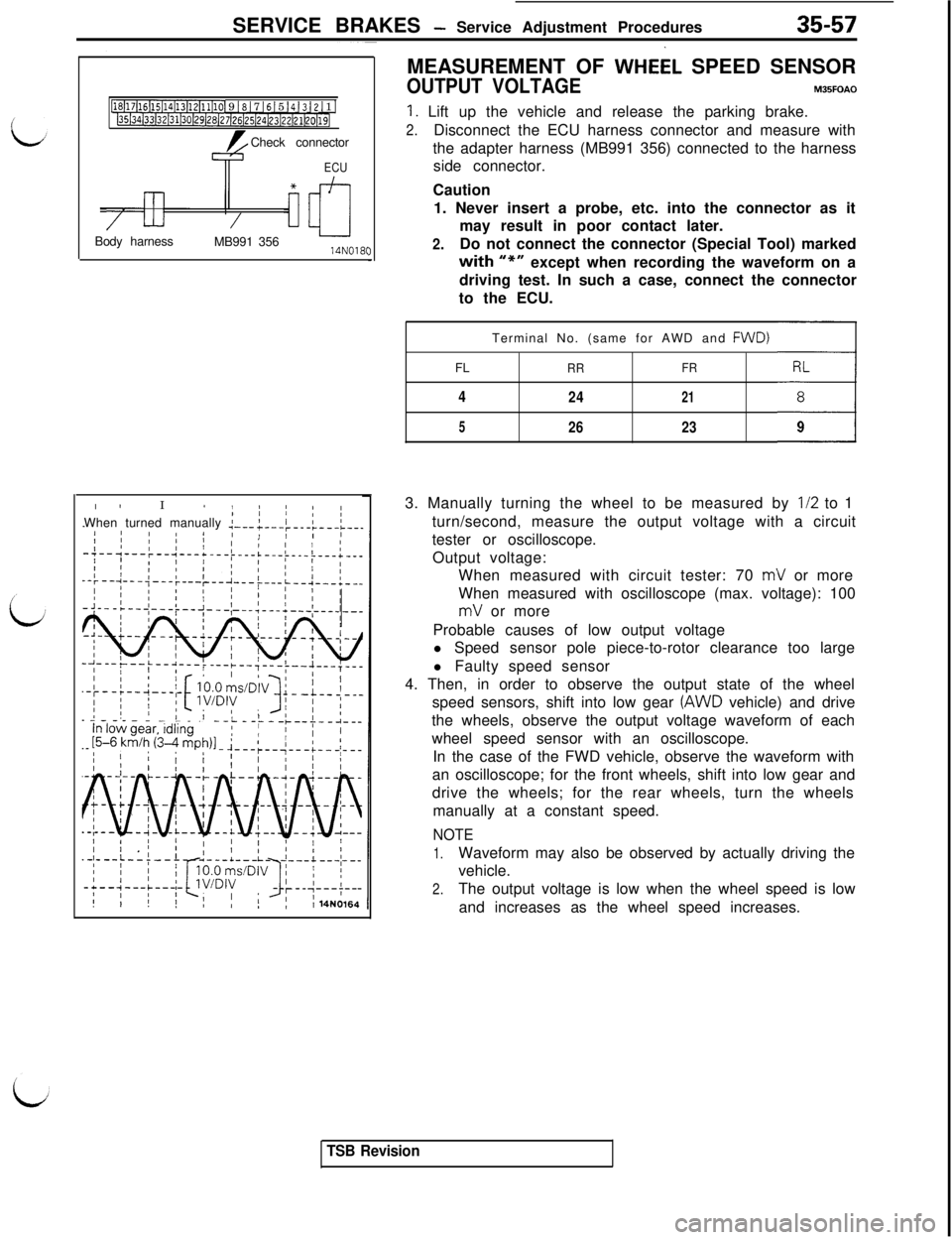
2.Disconnect the ECU harness connector and measure with
the adapter harness (MB991 356) connected to the harness
side connector.
Caution
1. Never insert a probe, etc. into the connector as it
may result in poor contact later.
2.Do not connect the connector (Special Tool) markedwith “r+”except when recording the waveform on a
driving test. In such a case, connect the connector
to the ECU.
Terminal No. (same for AWD and FWD)
FL
RRFRRL
4
24218
52623393. Manually turning the wheel to be measured by
112 to 1
turn/second, measure the output voltage with a circuit
tester or oscilloscope.
Output voltage:
When measured with circuit tester: 70
mV or more
When measured with oscilloscope (max. voltage): 100
mV or more
Probable causes of low output voltage
l Speed sensor pole piece-to-rotor clearance too large
l Faulty speed sensor
4. Then, in order to observe the output state of the wheel
speed sensors, shift into low gear
(AWD vehicle) and drive
the wheels, observe the output voltage waveform of each
wheel speed sensor with an oscilloscope.
In the case of the FWD vehicle, observe the waveform with
an oscilloscope; for the front wheels, shift into low gear and
drive the wheels; for the rear wheels, turn the wheels
manually at a constant speed.
NOTE
1.Waveform may also be observed by actually driving the
vehicle.
2.The output voltage is low when the wheel speed is low
and increases as the wheel speed increases.
TSB Revision
Page 780 of 1146
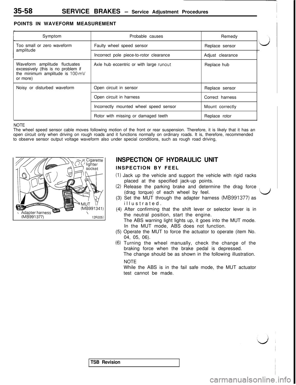
35-58SERVICE BRAKES - Service Adjustment Procedures
POINTS IN WAVEFORM MEASUREMENT
Symptom
Too small or zero waveform
amplitudeProbable causes
Faulty wheel speed sensorRemedy
Replace sensor
Incorrect pole piece-to-rotor clearance
Adjust clearance
Waveform amplitude fluctuates
excessively (this is no problem ifAxle hub eccentric or with large runout
Replace hub
the minimum amplitude is
100 mV
or more)
Noisy or disturbed waveformOpen circuit in sensor
Open circuit in harness
Incorrectly mounted wheel speed sensor
Rotor with missing or damaged teethReplace sensor
Correct harness
Mount correctly
Replace rotor
NOTEThe wheel speed sensor cable moves following motion of the front or rear suspension. Therefore, it is likely that it has an
open circuit only when driving on rough roads and it functions normally on ordinary roads. It is, therefore, recommended
to observe sensor output voltage waveform also under special conditions, such as rough road driving,
(ME!991 377)12FOO5i
INSPECTION OF HYDRAULIC UNITINSPECTION BY FEEL
(I) Jack up the vehicle and support the vehicle with rigid racks
placed at the specified jack-up points.
(2) Release the parking brake and determine the drag force
(drag torque) of each wheel by feel.
LJ(3) Set the MUT through the adapter harness (MB991377) as
illustrated.
(4) After confirming that the shift lever or selector lever is in
the neutral position, start the engine.
The ABS warning light lights up, it goes into the MUT mode.
In the MUT mode, ABS does not function.
(5) Operate the MUT to force the actuator to operate (item No.
04, 05, 06).
(6) Turning the wheel manually, check the change of the
braking force when the brake pedal is depressed.
The change should be as shown in the following illustration.
NOTEWhile the ABS is in the fail safe mode, the MUT actuator
test cannot be made.
TSB Revision