MITSUBISHI 3000GT 1991 Service Manual
Manufacturer: MITSUBISHI, Model Year: 1991, Model line: 3000GT, Model: MITSUBISHI 3000GT 1991Pages: 1146, PDF Size: 76.68 MB
Page 941 of 1146
/
L
,
LJEXTERIOR
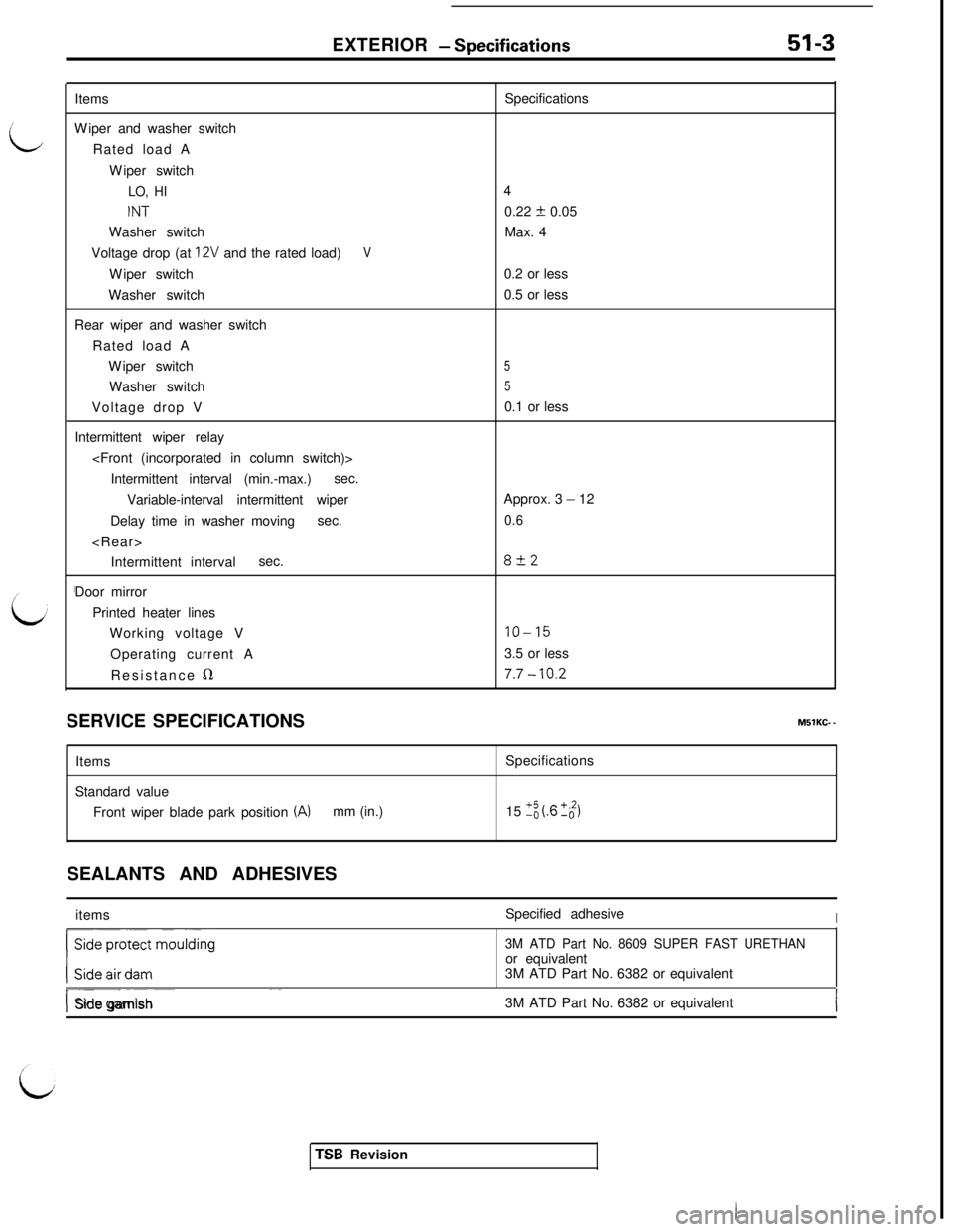
- SDecifications-a- - -~------~----ItemsSpecifications
Wiper and washer switch
Rated load A
Wiper switch
LO, HI4
INT0.22 f 0.05
Washer switchMax. 4
Voltage drop (at
12V and the rated load)VWiper switch0.2 or less
Washer switch0.5 or less
Rear wiper and washer switch
Rated load A
Wiper switch
5Washer switch
5Voltage drop V0.1 or less
Intermittent wiper relay
Intermittent interval (min.-max.)sec.
Variable-interval intermittent wiperApprox. 3
- 12
Delay time in washer movingsec.
0.6
Intermittent intervalsec.
8+2Door mirror
Printed heater lines
Working voltage V
IO-15Operating current A3.5 or less
Resistance
s17.7 - 10.2SERVICE SPECIFICATIONSMBlKC-
-ItemsSpecifications
Standard value
Front wiper blade park position
(A)mm (in.)15 ‘-; (.6 +_$ISEALANTS AND ADHESIVES
itemsSpecified adhesive
I
3M ATD Part No. 8609 SUPER FAST URETHANor equivalent
3M ATD Part No. 6382 or equivalent
r--- ~~Side garnish3M ATD Part No. 6382 or equivalent
TSB Revision
Page 942 of 1146
EXTERIOR - SDecial Tools
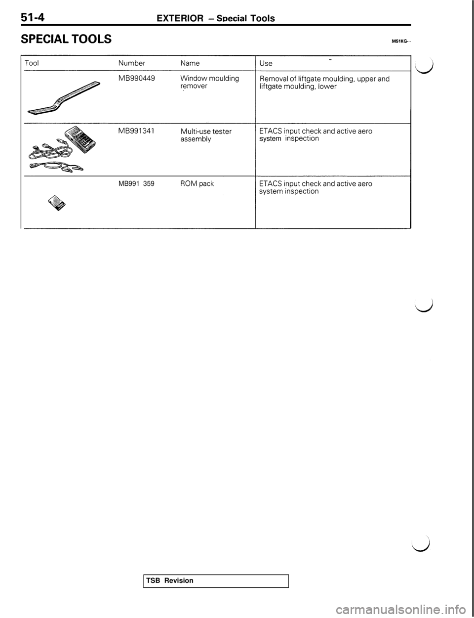
SPECIAL TOOLSMBlKG- .
I-system inspectlon
MB991 359TSB Revision
Page 943 of 1146
EXTERIOR - Troubleshooting51-5
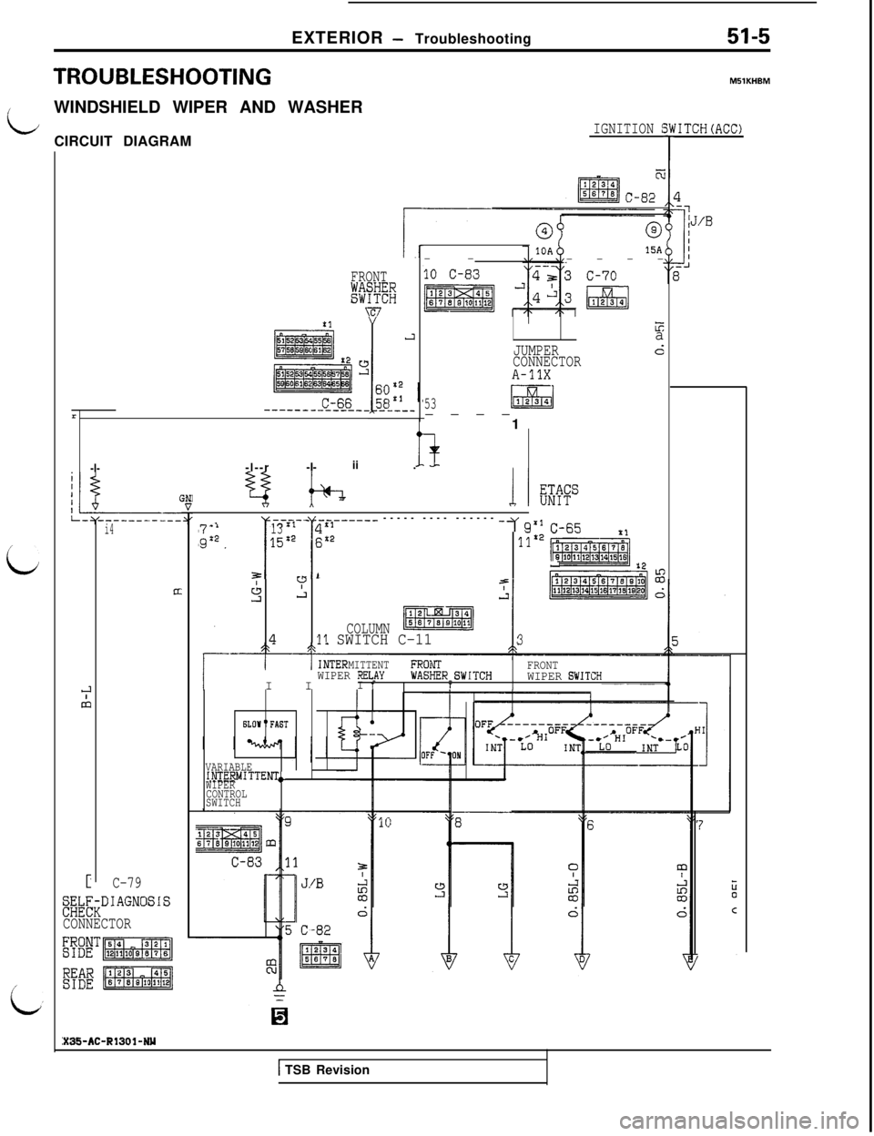
TROUBLESHOOTING
LWINDSHIELD WIPER AND WASHER
CIRCUIT DIAGRAMIGNITION :
i
ir
FRONT
KmYE7
-I--l--r-I-ii .
@
15A--
----
JUMPER
CONNECTOR
A-11X
Ea
d
53----
1
i4
CT
C-79
S&~DIAGNOSIS
CONNECTOR
EB'p%Jg@
g:f;:[pm1
:X35-AC-R1301-NY.:1
~;x2,--f-l--13L1------ ----- ---- ------ -7 q’,
I i
15:2 $x2
~-fi5
x3lTX2 pi2k%hw, :2~
3r,. I-EIv
s.LIjWl z
COLUMNn11 SWITCH C-113
MITTENTFROiiFRONTI IWIPER RELAYWIPER SWITCIII 1WASHER_SWITCHTI
34
TMSlKHBM
fITCH(ACC)
6LOll"FAST
VARIABLEINTERMITTENTo
WIPER
CONTROL
SWITCH
1 TSB Revision
Page 944 of 1146
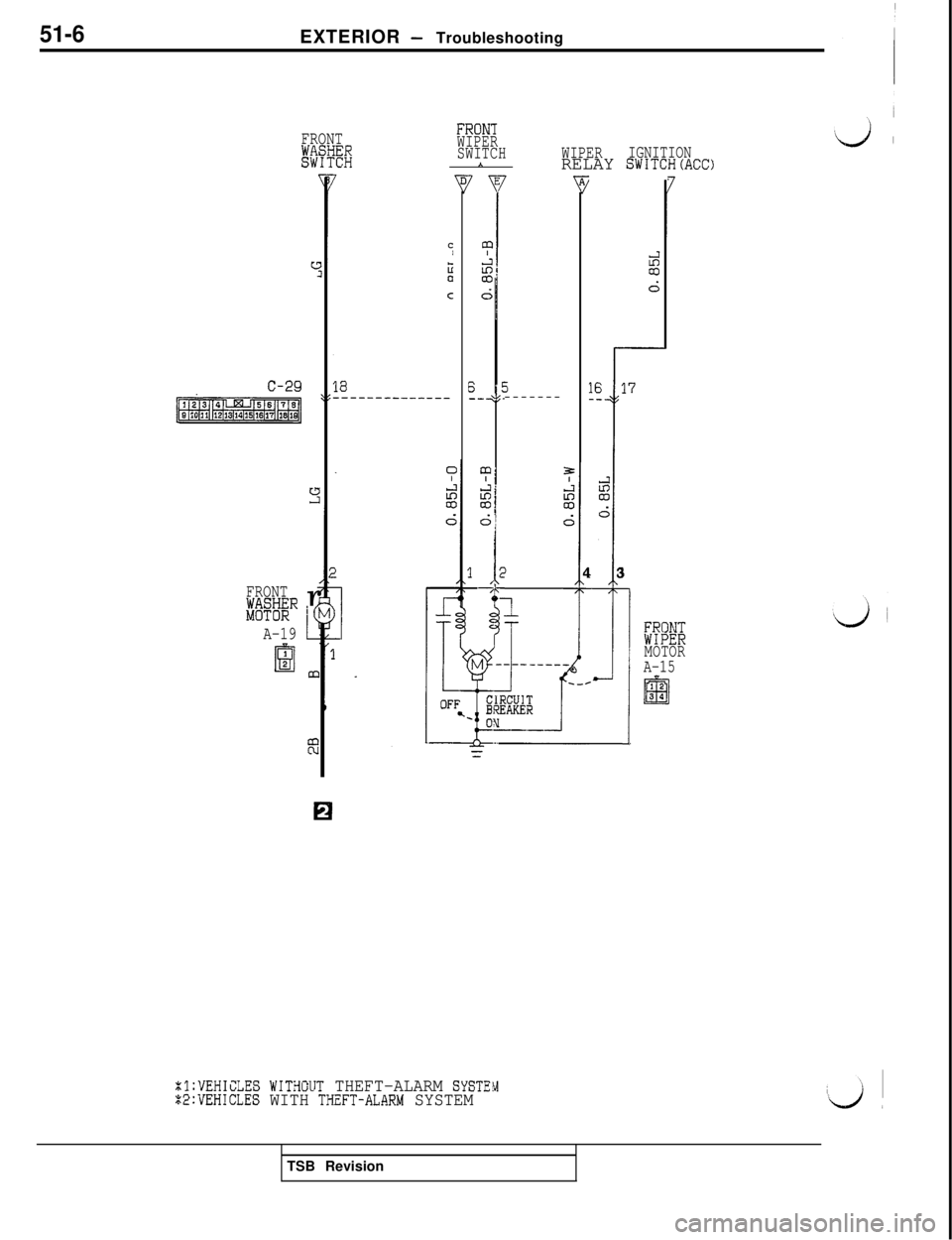
51-6EXTERIOR - Troubleshooting
FRONT
wm
c
c-29
[ml
FRONT
E%iRr‘(
A-19L
II:C
Iza
C
.---
FRON'IWIPER
SWITCH
*WIPERIGNITIONRELAY SWITCH(ACC)
7
$1
1
7I
I27’
jA -’
I--CII;BRE+lk
5-------
%l:VEHICLES WITHCUT THEFT-ALARM SYSTEUZ2:VEHICLES WITH THZFT-ALARM SYSTEM
1
I
------_
CUITFAKER
-.--I
5
5:CD
d
44 31
1
rEBRMOTOR
A-15TSB Revision
Page 945 of 1146
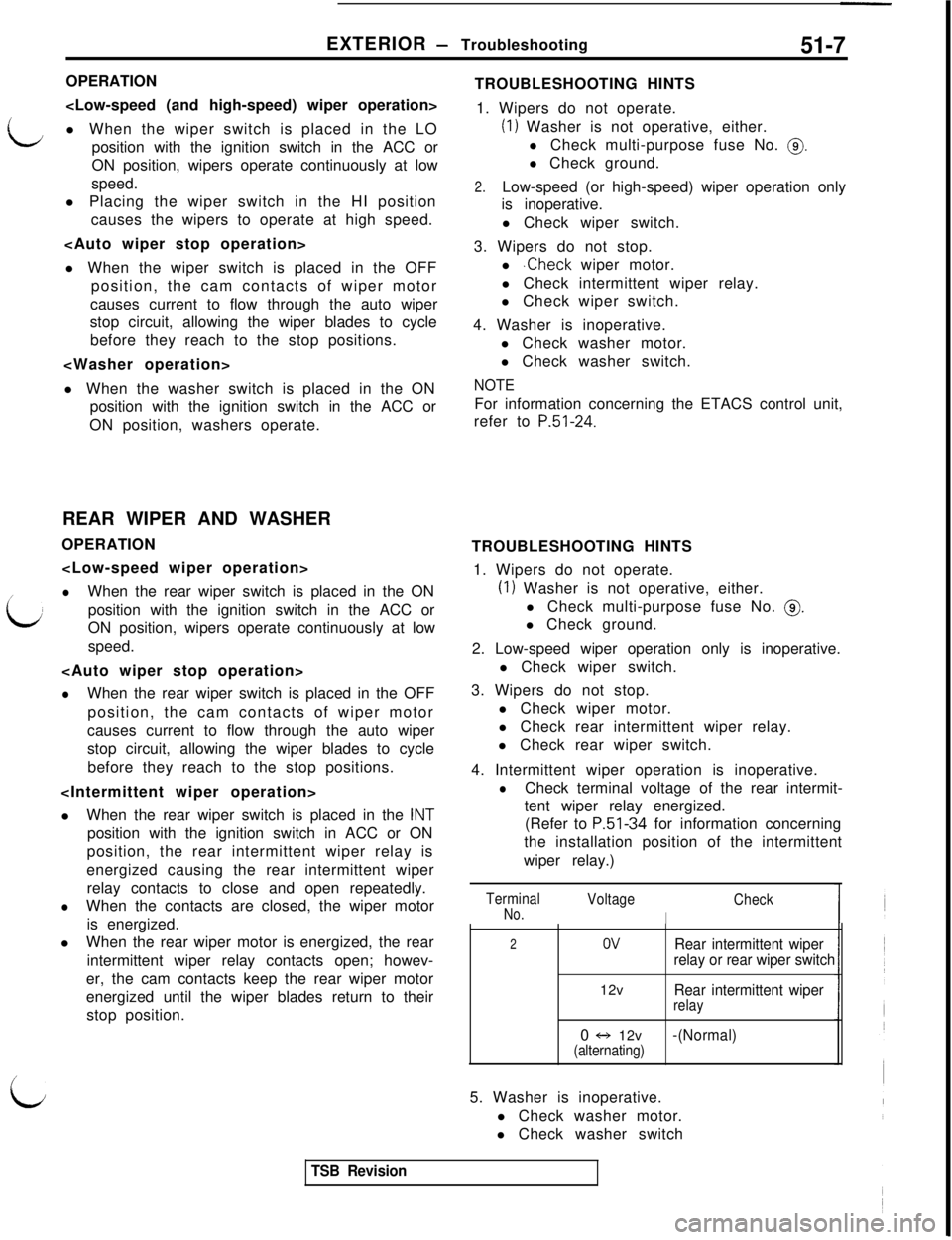
EXTERIOR - Troubleshooting51-7
LOPERATION
l When the wiper switch is placed in the LO
position with the ignition switch in the ACC or
ON position, wipers operate continuously at low
speed.
l Placing the wiper switch in the HI position
causes the wipers to operate at high speed.
l When the wiper switch is placed in the OFF
position, the cam contacts of wiper motor
causes current to flow through the auto wiper
stop circuit, allowing the wiper blades to cycle
before they reach to the stop positions.
l When the washer switch is placed in the ON
position with the ignition switch in the ACC or
ON position, washers operate.
REAR WIPER AND WASHER
OPERATION
/l
i,When the rear wiper switch is placed in the ON
position with the ignition switch in the ACC or
ON position, wipers operate continuously at low
speed.
lWhen the rear wiper switch is placed in the OFF
position, the cam contacts of wiper motor
causes current to flow through the auto wiper
stop circuit, allowing the wiper blades to cycle
before they reach to the stop positions.
lWhen the rear wiper switch is placed in the
INTposition with the ignition switch in ACC or ON
position, the rear intermittent wiper relay is
energized causing the rear intermittent wiper
relay contacts to close and open repeatedly.
lWhen the contacts are closed, the wiper motor
is energized.
lWhen the rear wiper motor is energized, the rear
intermittent wiper relay contacts open; howev-
er, the cam contacts keep the rear wiper motor
energized until the wiper blades return to their
stop position.
LTROUBLESHOOTING HINTS
1. Wipers do not operate.
(1) Washer is not operative, either.
l Check multi-purpose fuse No.
0.l Check ground.
2.Low-speed (or high-speed) wiper operation only
is inoperative.
l Check wiper switch.
3. Wipers do not stop.
l
.Check wiper motor.
l Check intermittent wiper relay.
l Check wiper switch.
4. Washer is inoperative.
l Check washer motor.
l Check washer switch.
NOTEFor information concerning the ETACS control unit,
refer to
P.51-24.TROUBLESHOOTING HINTS
1. Wipers do not operate.
(1) Washer is not operative, either.
l Check multi-purpose fuse No.
@.l Check ground.
2. Low-speed wiper operation only is inoperative.
l Check wiper switch.
3. Wipers do not stop.
l Check wiper motor.
l Check rear intermittent wiper relay.
l Check rear wiper switch.
4. Intermittent wiper operation is inoperative.
lCheck terminal voltage of the rear intermit-
tent wiper relay energized.
(Refer to
P.51-34 for information concerning
the installation position of the intermittent
wiper relay.)
TerminalNo.Voltage
I
Check
2OVRear intermittent wiper
relay or rear wiper switch12v
Rear intermittent wiperrelay0 f-, 12v
-(Normal)(alternating)5. Washer is inoperative.
l Check washer motor.
l Check washer switch
TSB Revision
Page 946 of 1146
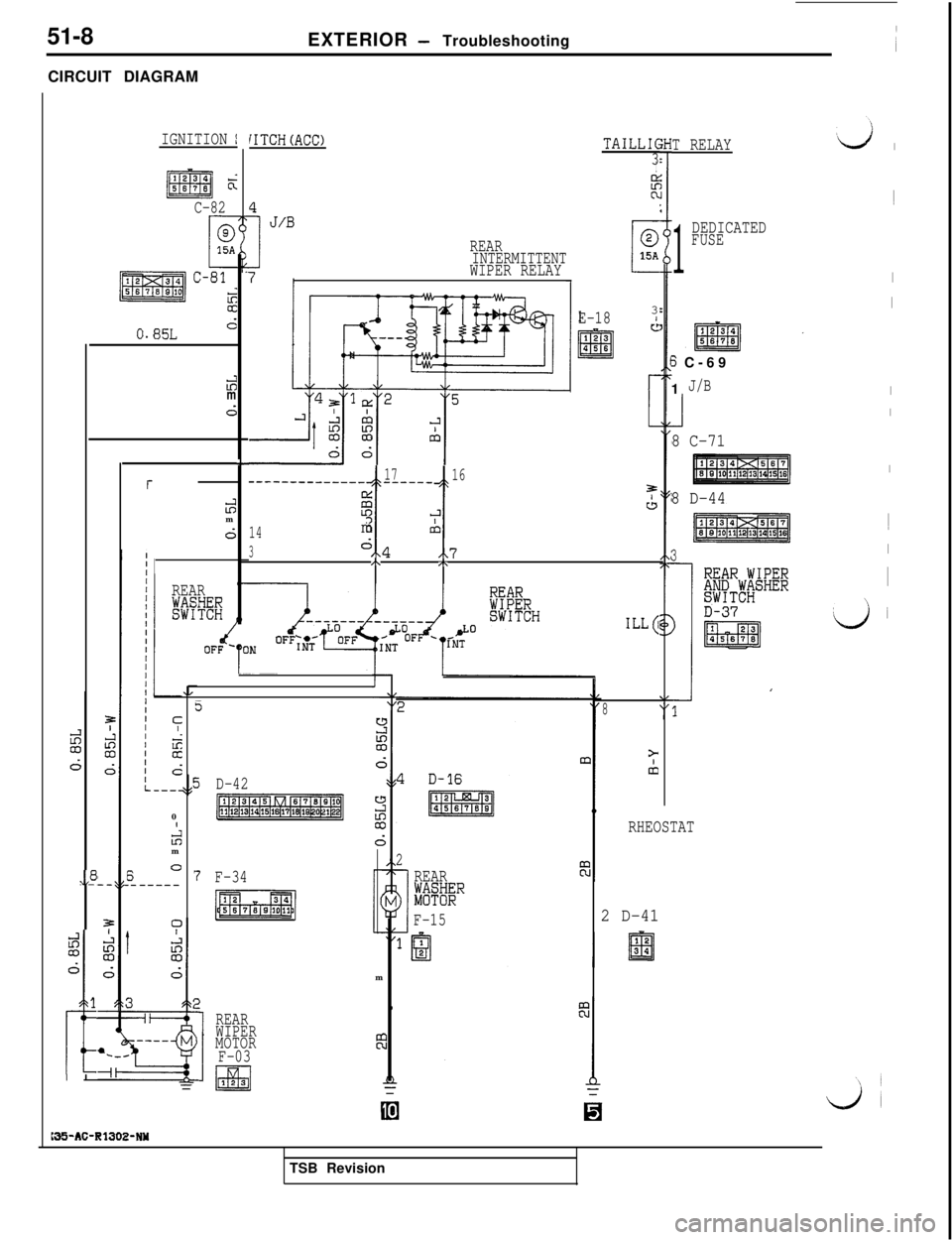
51-8
EXTERIOR - Troubleshooting
CIRCUIT DIAGRAM
IGNITION IiITCH(ACC)TAILLIC
3
I
F0.
REAR0
INTERMITTENTc15A
IWIPER RELAYI
E-1836
1417
16_----_-----_-- ----__
CL
t1
3
23J&m
0;
3
%x4/X7/\/\
I~
I
I
I
I
I~
I
I
‘4 i
T RELAY
C-82
1
DEDICATEDFUSE
0.85Ld
3 C-69
1
J/Bii+m
d1
8 C-71
L
ii?m
d
8 D-44
3
REAR
LmFi/ILL6
80
I
iim
6 O.------
5
,,8
D-42
-1
RHEOSTAT
2
REAR
iii%~~R
F-15 F-34pLi%Fq2 D-41
idm
d
I
1m
I
REAR
WIPER
MOTOR
F-03
w123
b5-AC-RlJOE-NYTSB Revision
Page 947 of 1146
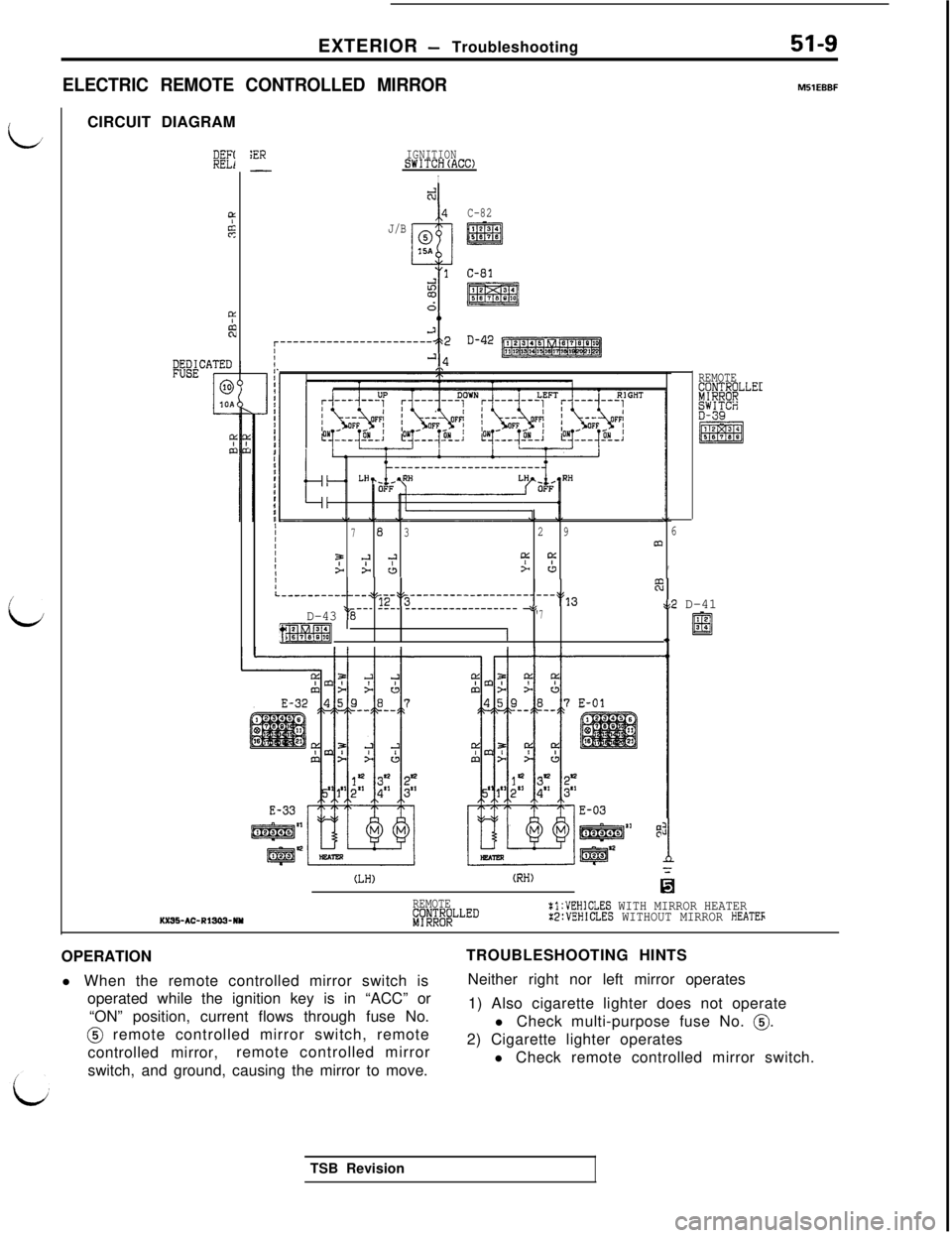
EXTERIOR - Troubleshooting
i.l
L
ELECTRIC REMOTE CONTROLLED MIRRORMSlEBBFCIRCUIT DIAGRAM
BEI
LLIfs
9LF?
PWATED
1
@iOA
w&
:ERIGNITIONSWITCH(ACC)-I
d
4
J/B
@ ::::15A
9
C-82
m
$i$iiq
:I1I’II
,IIIIIIII
IttI
1II,I
IIII
IIIt,
---------------------2 2
f
D-42
'-14
7
83296m9
-?;'9:c:a > c3> u,
REMOTEfjI#;"o;LLE'
EFti
tIL-------------q+1~-I~---------------------)L13w
.D-43 ‘1'8--- ---- ------------------ +’'7at2 D-41
/liRmqtI.) El::
:
1
(LH)(RH)
REMOTEiy;;I$)LLED:l:VEHICLES WITH MIRROR HEATERKXS-AC-R13C3-NYX2:VEHICLES WITHOUT MIRROR HEATEFOPERATION
l When the remote controlled mirror switch is
operated while the ignition key is in “ACC” or
“ON” position, current flows through fuse No.@ remote controlled mirror switch, remote
controlled mirror,remote controlled mirror
switch, and ground, causing the mirror to move.TROUBLESHOOTING HINTS
Neither right nor left mirror operates
1) Also cigarette lighter does not operate
l Check multi-purpose fuse No.
0.2) Cigarette lighter operates
l Check remote controlled mirror switch.
TSB Revision
Page 948 of 1146
51-10EXTERIOR - Service Adjustment Procedures
68FOO51
Multl-use tester
,SERVICE ADJUSTMENT PROCEDURES
INSPECTION OF ACTIVE AERO SYSTEM
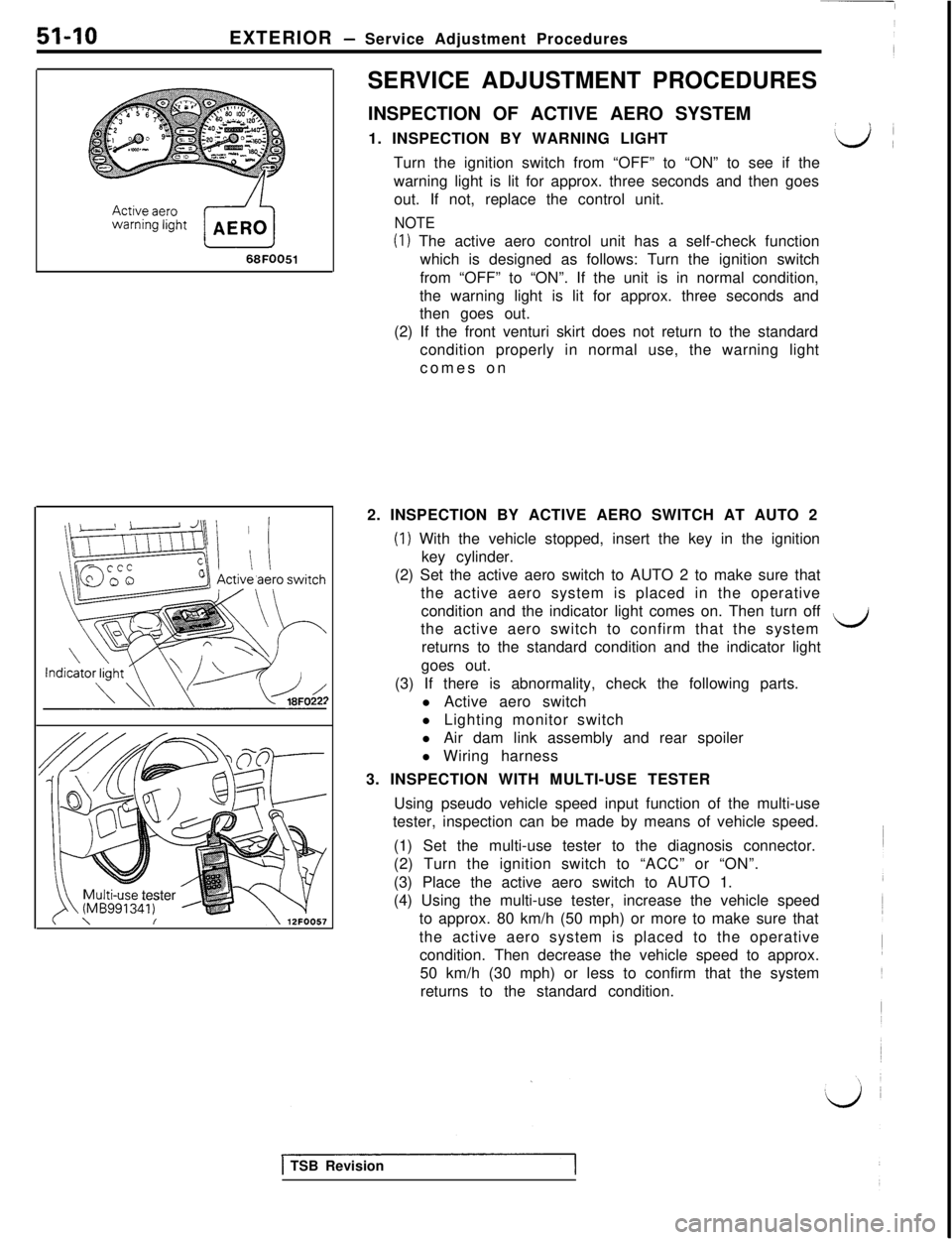
1. INSPECTION BY WARNING LIGHT
d!Turn the ignition switch from “OFF” to “ON” to see if the
warning light is lit for approx. three seconds and then goes
out. If not, replace the control unit.
NOTE
(1) The active aero control unit has a self-check function
which is designed as follows: Turn the ignition switch
from “OFF” to “ON”. If the unit is in normal condition,
the warning light is lit for approx. three seconds and
then goes out.
(2) If the front venturi skirt does not return to the standard
condition properly in normal use, the warning light
comes on
2. INSPECTION BY ACTIVE AERO SWITCH AT AUTO 2
(1) With the vehicle stopped, insert the key in the ignition
key cylinder.
(2) Set the active aero switch to AUTO 2 to make sure that
the active aero system is placed in the operative
condition and the indicator light comes on. Then turn off
the active aero switch to confirm that the system
LCJreturns to the standard condition and the indicator light
goes out.
(3) If there is abnormality, check the following parts.
l Active aero switch
l Lighting monitor switch
l Air dam link assembly and rear spoiler
l Wiring harness
3. INSPECTION WITH MULTI-USE TESTER
Using pseudo vehicle speed input function of the multi-use
tester, inspection can be made by means of vehicle speed.
(1) Set the multi-use tester to the diagnosis connector.
(2) Turn the ignition switch to “ACC” or “ON”.
(3) Place the active aero switch to AUTO 1.
(4) Using the multi-use tester, increase the vehicle speed
to approx. 80 km/h (50 mph) or more to make sure that
the active aero system is placed to the operative
condition. Then decrease the vehicle speed to approx.
50 km/h (30 mph) or less to confirm that the system
returns to the standard condition.
1 TSB Revision
Page 949 of 1146
/
iEXTERIOR
- Front Bumper51-11
We A
Installation
Grommet
Screw
Me B
Removal
Screw
t
10NOl8718N0185
installation
t18N018818N0184
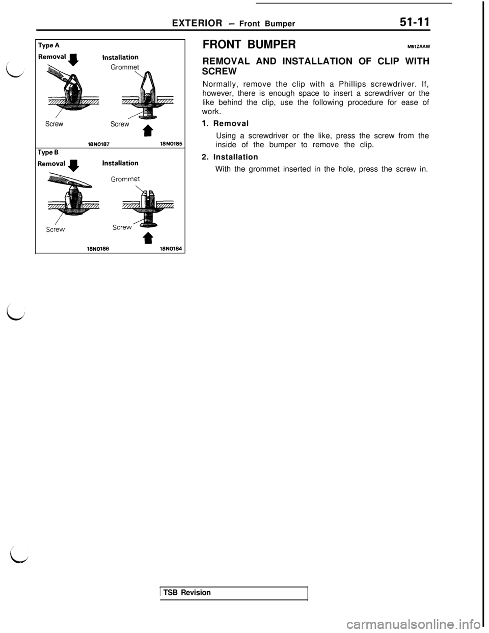
FRONT BUMPERM51ZAAW
REMOVAL AND INSTALLATION OF CLIP WITH
SCREW
Normally, remove the clip with a Phillips screwdriver. If,
however, there is enough space to insert a screwdriver or the
like behind the clip, use the following procedure for ease of
work.
1. Removal
Using a screwdriver or the like, press the screw from the
inside of the bumper to remove the clip.
2. Installation
With the grommet inserted in the hole, press the screw in.
1 TSB Revision
I’
L
Page 950 of 1146
51-12EXTERIOR - Front BummerIREMOVAL
,AND INSTALLATION
9
F IL
d.94Lag
.d,
;3
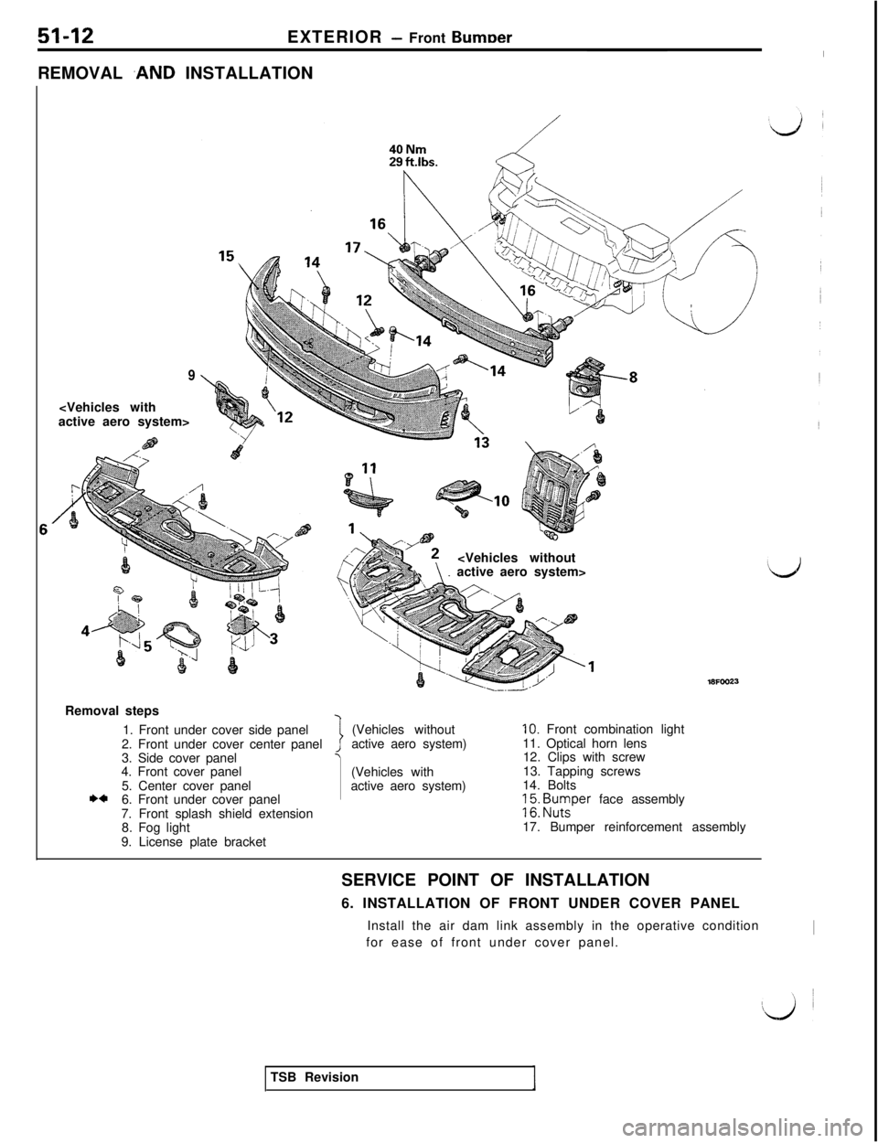
\Removal steps
1. Front under cover side panel
2. Front under cover center panel
3. Side cover panel
4. Front cover panel
5. Center cover panel
I)*6. Front under cover panel
7. Front splash shield extension
8. Fog light
9. License plate bracket
7i(Vehicles without
active aero system)
(Vehicles with
active aero system)
10. Front combination light
11. Optical horn lens
12. Clips with screw
13. Tapping screws
14. Bolts;
51: Bu;per face assembly
17. Bumper reinforcement assembly
SERVICE POINT OF INSTALLATION
6. INSTALLATION OF FRONT UNDER COVER PANEL
Install the air dam link assembly in the operative condition
for ease of front under cover panel.
ITSB Revision