MITSUBISHI 3000GT 1991 Service Manual
Manufacturer: MITSUBISHI, Model Year: 1991, Model line: 3000GT, Model: MITSUBISHI 3000GT 1991Pages: 1146, PDF Size: 76.68 MB
Page 951 of 1146
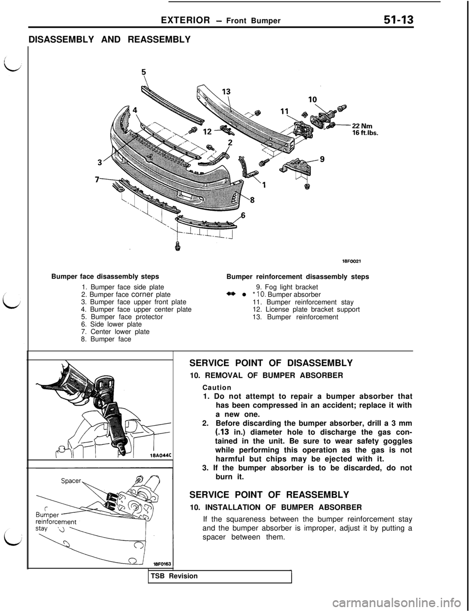
EXTERIOR - Front Bumper51-13DISASSEMBLY AND REASSEMBLY
22 Nm16 ftlbs.
Bumper face disassembly steps
1. Bumper face side plate
2. Bumper face corner plate
3. Bumper face upper front plate
4. Bumper face upper center plate
5. Bumper face protector
6. Side lower plate
7. Center lower plate
8. Bumper faceBumper reinforcement disassembly steps
9. Fog light bracket
** l * IO. Bumper absorber
11. Bumper reinforcement stay
12. License plate bracket support
13. Bumper reinforcement
SERVICE POINT OF DISASSEMBLY
10. REMOVAL OF BUMPER ABSORBER
Caution
1. Do not attempt to repair a bumper absorber that
has been compressed in an accident; replace it with
a new one.
2.Before discarding the bumper absorber, drill a 3 mm(.13 in.) diameter hole to discharge the gas con-
tained in the unit. Be sure to wear safety goggles
while performing this operation as the gas is not
harmful but chips may be ejected with it.
3. If the bumper absorber is to be discarded, do not
burn it.
SERVICE POINT OF REASSEMBLY
10. INSTALLATION OF BUMPER ABSORBER
If the squareness between the bumper reinforcement stay
and the bumper absorber is improper, adjust it by putting a
spacer between them.
TSB Revision
Page 952 of 1146
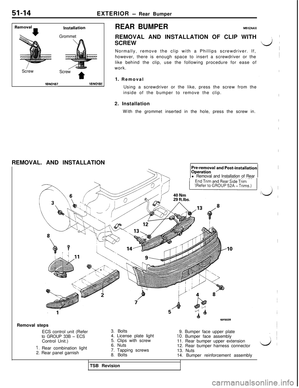
EXTERIOR - Rear Bumper
ScrewGrommet
Screw
t
REAR BUMPERMllZAAXREMOVAL AND INSTALLATION OF CLIP WITH
SCREW
Normally, remove the clip with a Phillips screwdriver. If,
however, there is enough space to insert a screwdriver or the
like behind the clip, use the following procedure for ease of
work.
1. Removal
Using a screwdriver or the like, press the screw from the
inside of the bumper to remove the clip.
2. Installation
With the grommet inserted in the hole, press the screw in.
REMOVAL. AND INSTALLATION
/Pre-removal and Post-installationOperationlRemoval and Installation of RearRemovalsteps
ECS control unit (Refer
to GROUP 33B - ECSControl Unit.)
1. Rear combination light
2. Rear panel garnish3. Bolts
4. License plate light
5. Clips with screw
6. Nuts
7. Tapping screws
8. Bolts9. Bumper face upper plate
10. Bumper face assembly
11. Rear bumper upper extension
12. Rear bumper harness connector
LA’13. Nuts
14. Bumper reinforcement assembly
I
d ’~
I
I
I
I
I
I
Ld;
I1
TSB Revision
Page 953 of 1146
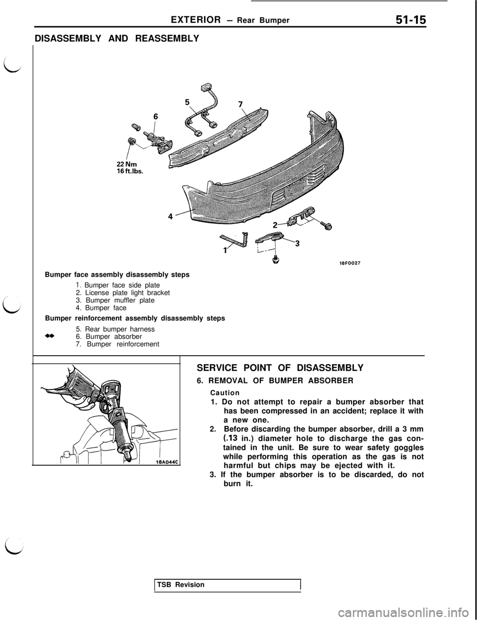
EXTERIOR - Rear Bumper
DISASSEMBLY AND REASSEMBLY51-15
221618FOO27
Bumper face assembly disassembly steps
I. Bumper face side plate
2. License plate light bracket
3. Bumper muffler plate
4. Bumper face
Bumper reinforcement assembly disassembly steps
5. Rear bumper harness
+I)6. Bumper absorber
7. Bumper reinforcement
SERVICE POINT OF DISASSEMBLY
6. REMOVAL OF BUMPER ABSORBER
Caution
1. Do not attempt to repair a bumper absorber that
has been compressed in an accident; replace it with
a new one.
2.Before discarding the bumper absorber, drill a 3 mm(.13 in.) diameter hole to discharge the gas con-
tained in the unit. Be sure to wear safety goggles
while performing this operation as the gas is not
harmful but chips may be ejected with it.
3. If the bumper absorber is to be discarded, do not
burn it.
TSB Revision
Page 954 of 1146
51-16
EXTERIOR - Garnishes and Mouldings
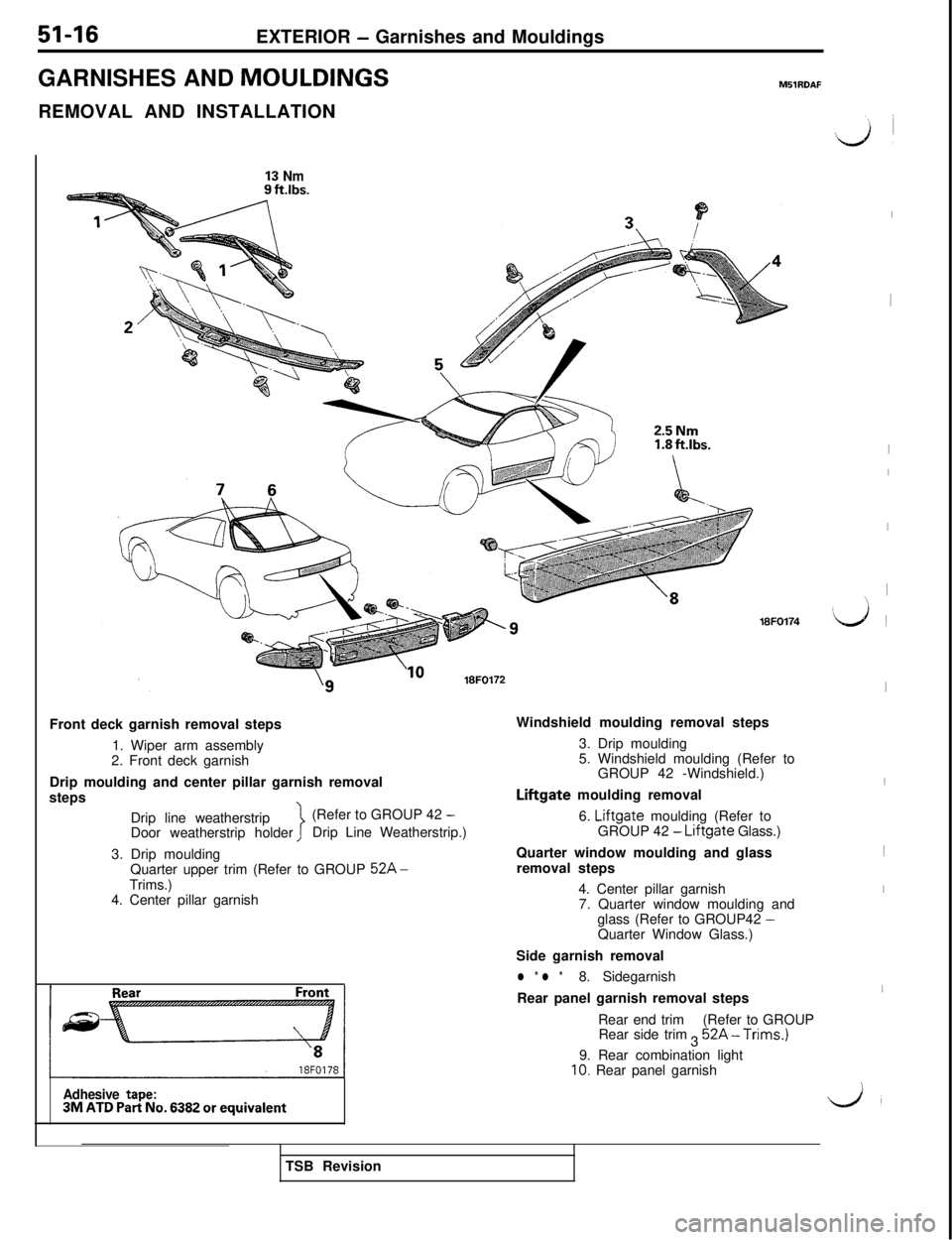
GARNISHES AND MOULDINGS
M51RDAFREMOVAL AND INSTALLATION
13 Nm2.5Nm18FO174
Front deck garnish removal steps
1. Wiper arm assembly
2. Front deck garnish
Drip moulding and center pillar garnish removal
steps
Drip line weatherstrip(Refer to GROUP 42
-Door weatherstrip holderDrip Line Weatherstrip.)
3. Drip moulding
Quarter upper trim (Refer to GROUP
52A-Trims.)
4. Center pillar garnish
Adhesive tape:3M ATD Part No. 6382 or equivalentWindshield moulding removal steps
3. Drip moulding
5. Windshield moulding (Refer to
GROUP 42 -Windshield.)
Liftgate moulding removal
6.
Liftgate moulding (Refer to
GROUP 42 - Liftgate Glass.)
Quarter window moulding and glass
removal steps
4. Center pillar garnish
7. Quarter window moulding and
glass (Refer to GROUP42
-Quarter Window Glass.)
Side garnish removal
l * l *8. Sidegarnish
Rear panel garnish removal steps
Rear end trim
Rear side trim
3(Refer to GROUP
52A-Trims.)9. Rear combination light
10. Rear panel garnish
I
I
I
I
I1
~
:Ij ~
I
I1
I
I
L.JTSB Revision
Page 955 of 1146
EXTERIOR - Garnishes and Mouldings51-17
Protective tape/
i
I18FO181
Pressure sensitive
double-sided tape
Resin spatulaSERVICE POINT OF REMOVAL
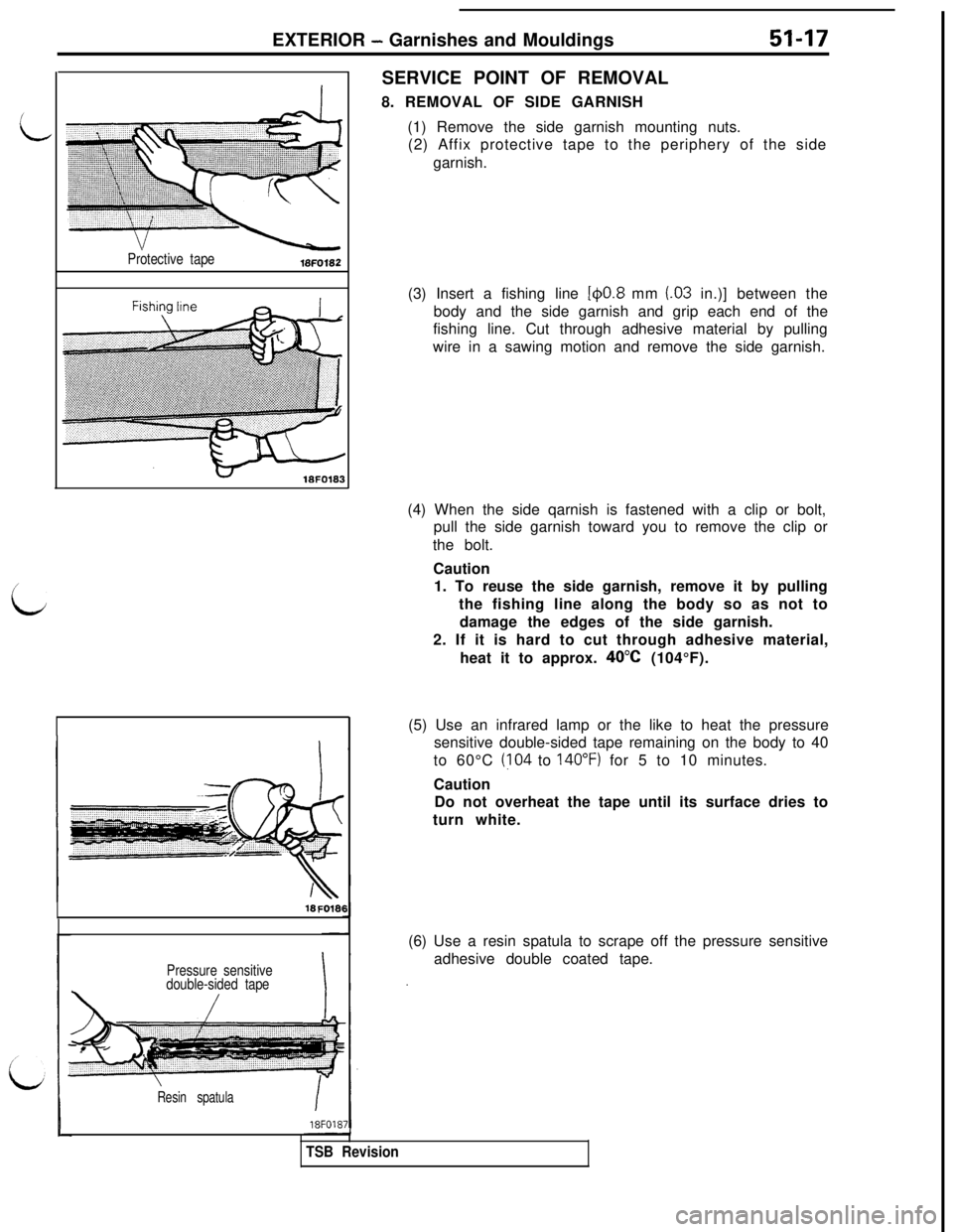
8. REMOVAL OF SIDE GARNISH
(1) Remove the side garnish mounting nuts.
(2) Affix protective tape to the periphery of the side
garnish.
(3) Insert a fishing line
[@0.8 mm (03 in.)] between the
body and the side garnish and grip each end of the
fishing line. Cut through adhesive material by pulling
wire in a sawing motion and remove the side garnish.
(4) When the side qarnish is fastened with a clip or bolt,
pull the side garnish toward you to remove the clip or
the bolt.
Caution
1. To reuse the side garnish, remove it by pulling
the fishing line along the body so as not to
damage the edges of the side garnish.
2. If it is hard to cut through adhesive material,
heat it to approx.
40°C (104°F).-I
TSB Revision(5) Use an infrared lamp or the like to heat the pressure
sensitive double-sided tape remaining on the body to 40
to 60°C
(?04 to 140°F) for 5 to 10 minutes.
Caution
Do not overheat the tape until its surface dries to
turn white.
(6) Use a resin spatula to scrape off the pressure sensitive
adhesive double coated tape.
Page 956 of 1146
51-18EXTERIOR - Garnishes and Mouldings
~~~,~,.
. . . .>cpe
~-~~~~~o
18FO19;,
RearFront
Pressure sensitive
double-sided tape
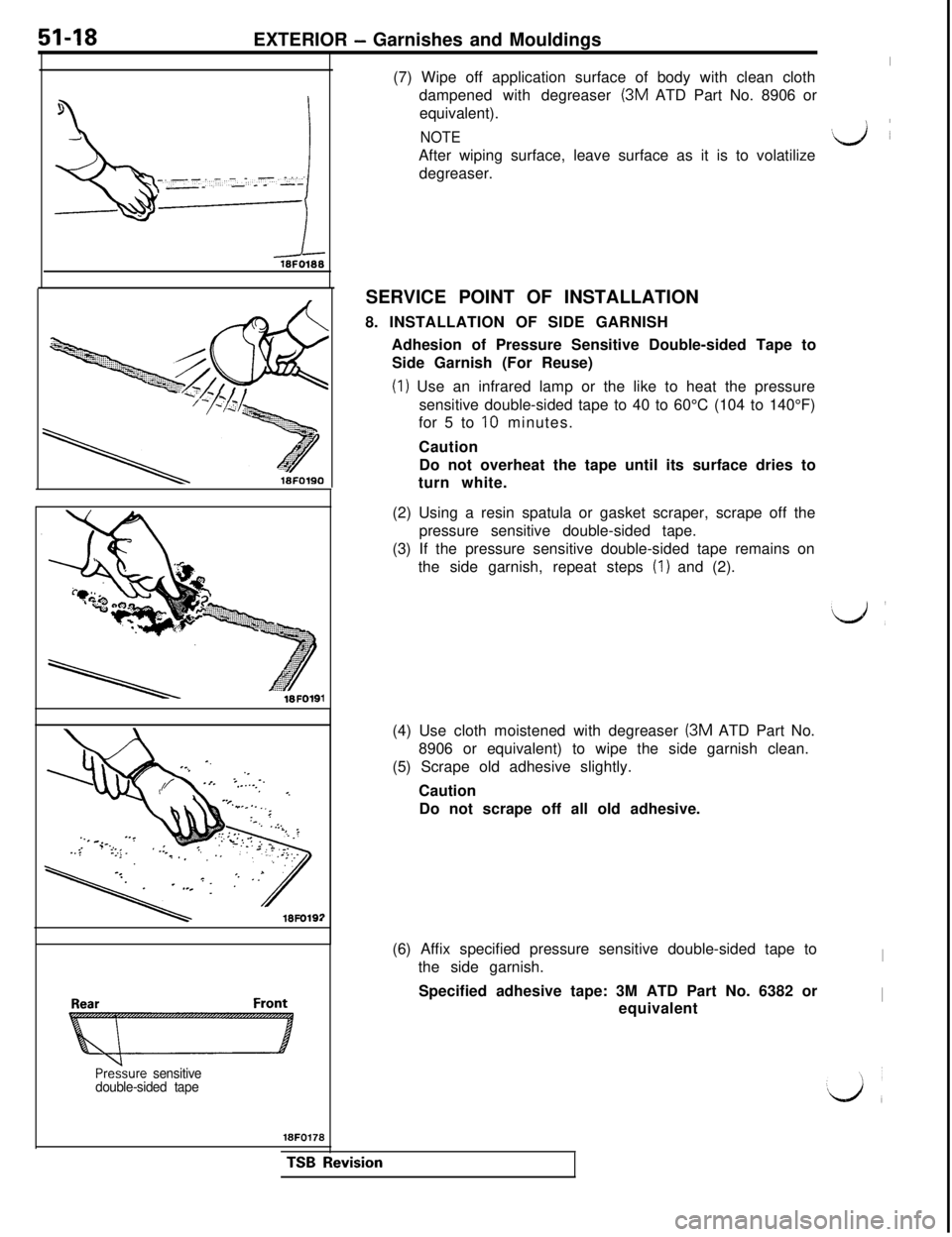
18FO178(7) Wipe off application surface of body with clean cloth
dampened with degreaser (3M ATD Part No. 8906 or
equivalent).
NOTEGJ ~
After wiping surface, leave surface as it is to volatilize
degreaser.
SERVICE POINT OF INSTALLATION
8. INSTALLATION OF SIDE GARNISH
Adhesion of Pressure Sensitive Double-sided Tape to
Side Garnish (For Reuse)
(1) Use an infrared lamp or the like to heat the pressure
sensitive double-sided tape to 40 to 60°C (104 to 140°F)
for 5 to
10 minutes.
Caution
Do not overheat the tape until its surface dries to
turn white.
(2) Using a resin spatula or gasket scraper, scrape off the
pressure sensitive double-sided tape.
(3) If the pressure sensitive double-sided tape remains on
the side garnish, repeat steps
(1) and (2).
(4) Use cloth moistened with degreaser
(3M ATD Part No.
8906 or equivalent) to wipe the side garnish clean.
(5) Scrape old adhesive slightly.
Caution
Do not scrape off all old adhesive.
(6) Affix specified pressure sensitive double-sided tape to
the side garnish.
ISpecified adhesive tape: 3M ATD Part No. 6382 or
equivalent
ITSB Revision
Page 957 of 1146
EXTERIOR - Garnishes and Mouldings51-19
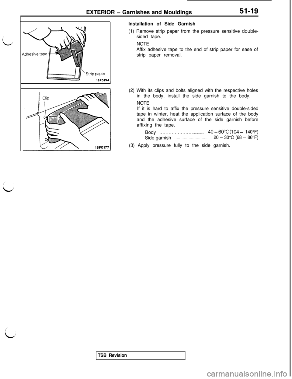
18FO194Installation of Side Garnish
(1) Remove strip paper from the pressure sensitive double-
sided tape.
NOTEAffix adhesive tape to the end of strip paper for ease of
strip paper removal.
(2) With its clips and bolts aligned with the respective holes
in the body, install the side garnish to the body.
NOTEIf it is hard to affix the pressure sensitive double-sided
tape in winter, heat the application surface of the body
and the adhesive surface of the side garnish before
affixing the tape.
Body
. . . . . . . . . . . . . . . . . . . . . . .._...........40-60°C (104- 140°F)Side garnish
. . . . . . . . . . . . . . . . . . . . . . . . . . . .20 - 30°C (68 - 86°F)(3) Apply pressure fully to the side garnish.
TSB Revision
Page 958 of 1146
51-20EXTERIOR - Aero Parts
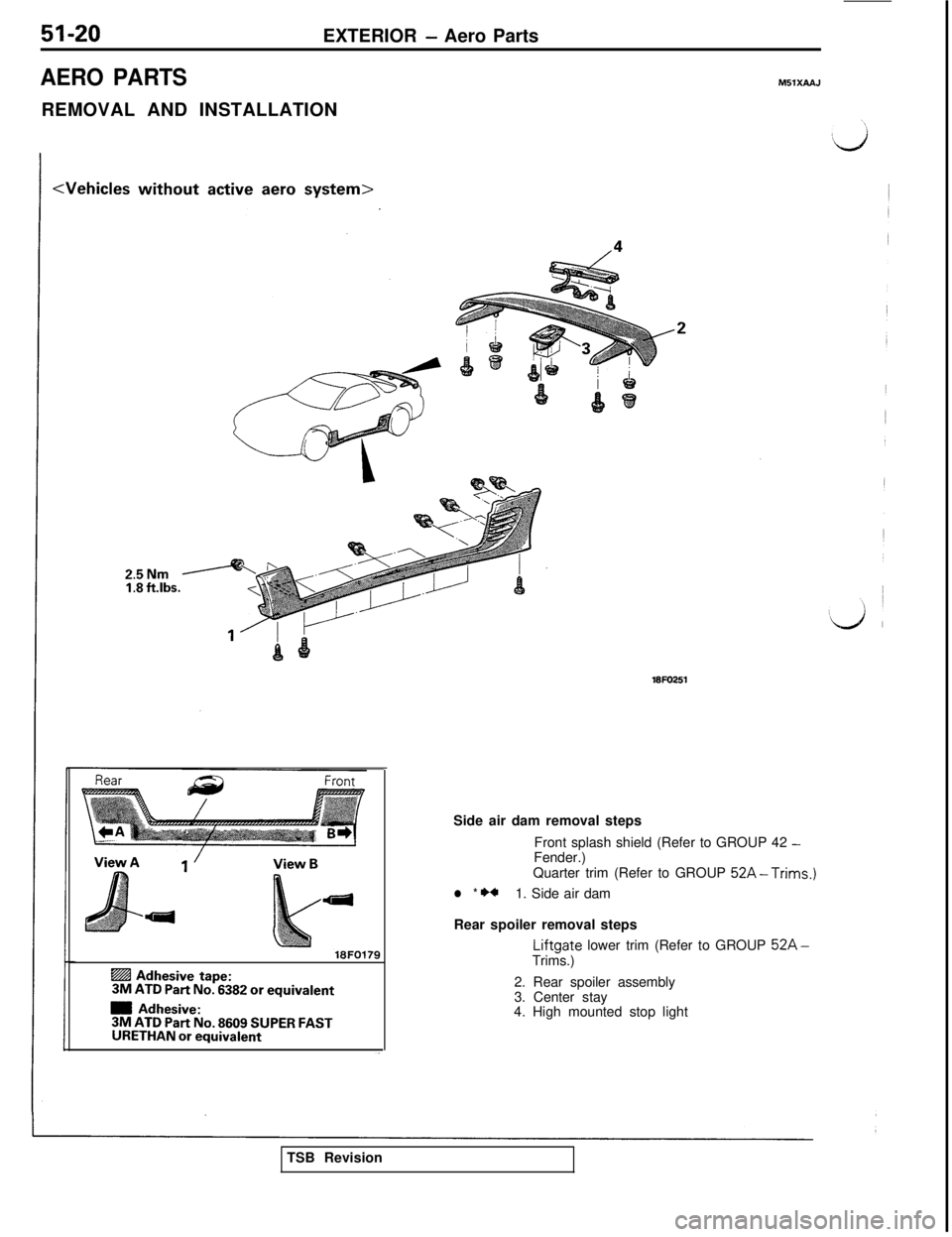
AERO PARTSM5lXAA.J
REMOVAL AND INSTALLATION
25NmI:8 ft.lbs.
18FO179
@ Adhesive tape:3M ATD Part No. 6382 or equivalent
m Adhesive:3M ATD Part No. 8609 SUPER FASTURETHAN or equivalent
18FO251Side air dam removal steps
Front splash shield (Refer to GROUP 42
-Fender.)
Quarter trim (Refer to GROUP
52A-Trims.)
l * **1. Side air dam
Rear spoiler removal steps
Liftgate lower trim (Refer to GROUP 52A-Trims.)
2. Rear spoiler assembly
3. Center stay
4. High mounted stop light
TSB Revision
Page 959 of 1146
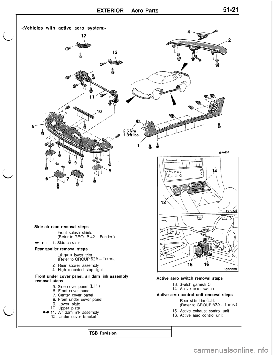
EXTERIOR - Aero Parts51-21
8
Side air dam removal steps
Front splash shield
(Refer to GROUP 42
- Fender.)
+I) l +1. Side airdamRear spoiler removal steps
Liftgate lower trim
(Refer to GROUP 52A-Trims.)2. Rear spoiler assembly
4. High mounted stop light
Front under cover panel, air dam link assembly
removal steps
5. Side cover panel
(L.H.)6. Front cover panel
7. Center cover panel
8. Front under cover panel
9. Lower plate
10. Upper plateI)* 11. Air dam link assembly
12. Under cover bracket
16FO252
16FOO53Active aero switch removal steps
13. Switch garnish C
14. Active aero switch
Active aero control unit removal steps
Rear side trim
(L.H.)(Refer to GROUP 52A-Trims.)15. Active exhaust control unit
16. Active aero control unitTSB Revision
Page 960 of 1146
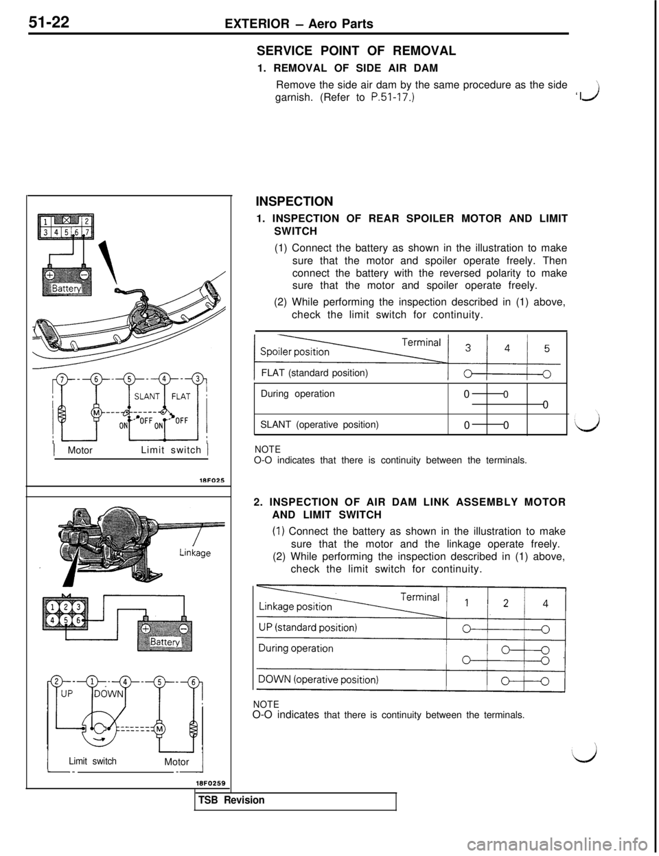
51-22
EXTERIOR - Aero Parts
1 MotorLimit switch )
iLimit switch--Motor /_I
18FO259SERVICE POINT OF REMOVAL
1. REMOVAL OF SIDE AIR DAM
Remove the side air dam by the same procedure as the side
’garnish. (Refer to P.51-17.)‘IJINSPECTION
1. INSPECTION OF REAR SPOILER MOTOR AND LIMIT
SWITCH
(1) Connect the battery as shown in the illustration to make
sure that the motor and spoiler operate freely. Then
connect the battery with the reversed polarity to make
sure that the motor and spoiler operate freely.
(2) While performing the inspection described in (1) above,
check the limit switch for continuity.
FLAT (standard position)
During operation
00
0
SLANT (operative position)
00
NOTEO-O indicates that there is continuity between the terminals.
2. INSPECTION OF AIR DAM LINK ASSEMBLY MOTOR
AND LIMIT SWITCH
(1) Connect the battery as shown in the illustration to make
sure that the motor and the linkage operate freely.
(2) While performing the inspection described in (1) above,
check the limit switch for continuity.
NOTEO-O indicates that there is continuity between the terminals.
TSB Revision