engine MITSUBISHI 380 2005 Service Manual
[x] Cancel search | Manufacturer: MITSUBISHI, Model Year: 2005, Model line: 380, Model: MITSUBISHI 380 2005Pages: 1500, PDF Size: 47.87 MB
Page 831 of 1500
AUTO A/C DIAGNOSIS
HEATER, AIR CONDITIONING AND VENTILATION55-130
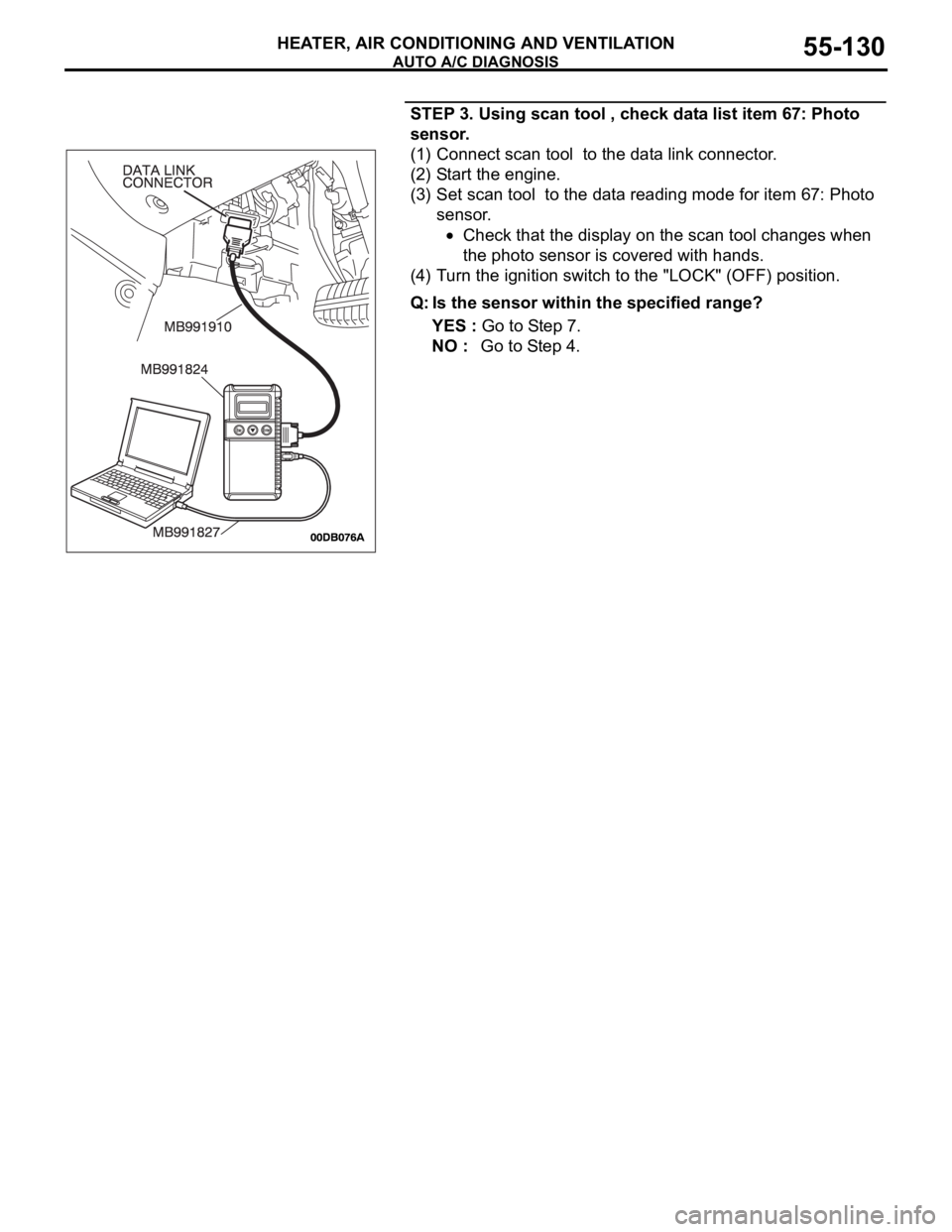
STEP 3. Using scan tool , check data list item 67: Photo
sensor.
(1) Connect scan tool to the data link connector.
(2) Start the engine.
(3) Set scan tool to the data reading mode for item 67: Photo
sensor.
Check that the display on the scan tool changes when
the photo sensor is covered with hands.
(4) Turn the ignition switch to the "LOCK" (OFF) position.
Q: Is the sensor within the specified range?
YES : Go to Step 7.
NO : Go to Step 4.
Page 834 of 1500

AUTO A/C DIAGNOSIS
HEATER, AIR CONDITIONING AND VENTILATION55-133
DATA LIST REFERENCE TABLEM1554005100136
MUT-III
DIAGNOSTIC
TOOL DISPLAYITEM
NO.INSPECTION ITEM INSPECTION REQUIREMENT NORMAL VALUE
Inside
temperature
sensor59 Interior temperature
sensorIgnition switch: ON Inside air
temperature and
temperature
displayed on the
diagnostic tool are
identical.
Outside
temperature
sensor58 Outside temperature
sensorIgnition switch: ON Outside air
temperature and
temperature
displayed on the
diagnostic tool are
identical.
Air thermo sensor 20 Air thermo sensor Ignition switch: ON The temperature
measured behind
the evaporator
matches the
displayed value on
the diagnostic tool
while the engine is
cold.
Pressure sensor 61 A/C pressure sensor Ignition switch: ON Measured refrigerant
pressure is nearly
equal to the value
shown on the
diagnostic tool
(MPa).
Water
temperature
sensor62 Engine coolant
temperature sensor
(Data received by
CAN
Communication)Ignition switch: ON Engine coolant
temperature and
temperature
displayed on the
diagnostic tool are
identical.
Photo sensor 67 Photo sensor Ignition switch: ON Amount of light is
proportional to
voltage displayed on
the diagnostic tool.
Air mix
potentiometer63 Air mixing damper
control motor
potentiometerIgnition switch: ON Damper
positionOpening degree (V)
MAX. HOT Approx. 5
MAX. COOL Approx. 0
Air mix
potentiometer
(Target)64 Target value for air
mixing damper
control motor
potentiometerIgnition switch: ON Damper
positionOpening degree (V)
MAX. HOT Approx. 5
MAX. COOL Approx. 0
Page 836 of 1500

AUTO A/C DIAGNOSIS
HEATER, AIR CONDITIONING AND VENTILATION55-135
Temperature
setting23 Temperature setting
actualIgnition switch: ON The actual setting
corresponds with
diagnostic tool
display.
Vehicle speed 26 Actual vehicle speed Ignition switch: ON The vehicle speed
corresponds with
diagnostic tool
display.
A/C compressor
drive request27 Compressor clutch Engine: ON
Compressor:
ONDiagnostic tool
indication: "ON"
Compressor:
OFFDiagnostic tool
indication: "OFF"
Illumination 15 Display lighting Ignition switch: ON
Lights: ON
Diagnostic tool
indication: "ON"
Lights: OFF
Diagnostic tool
indication: "OFF"
Engine speed 23 Actual engine speed Engine: ON The engine speed
corresponds with
diagnostic tool
display.
In/out air select
switch state3 In/out air select
switch Ignition switch: ON In/out air
switch: ONDiagnostic tool
indication: "pressed"
In/out air
switch: OFFDiagnostic tool
indication: "release"
Rear defogger
relay72 Rear defogger relay Ignition switch: ON
Rear defogger:
ONDiagnostic tool
indication: "ON"
Rear defogger:
OFFDiagnostic tool
indication: "OFF" MUT-III
DIAGNOSTIC
TOOL DISPLAYITEM
NO.INSPECTION ITEM INSPECTION REQUIREMENT NORMAL VALUE
Page 842 of 1500
ON-VEHICLE SERVICE
HEATER, AIR CONDITIONING AND VENTILATION55-141
ON-VEHICLE SERVICE
REFRIGERANT LEVEL TESTM1552008400408
Use the refrigerant recovery station to remove all of the refrig-
erant, and then calculate the amount of the refrigerant and
charge it.
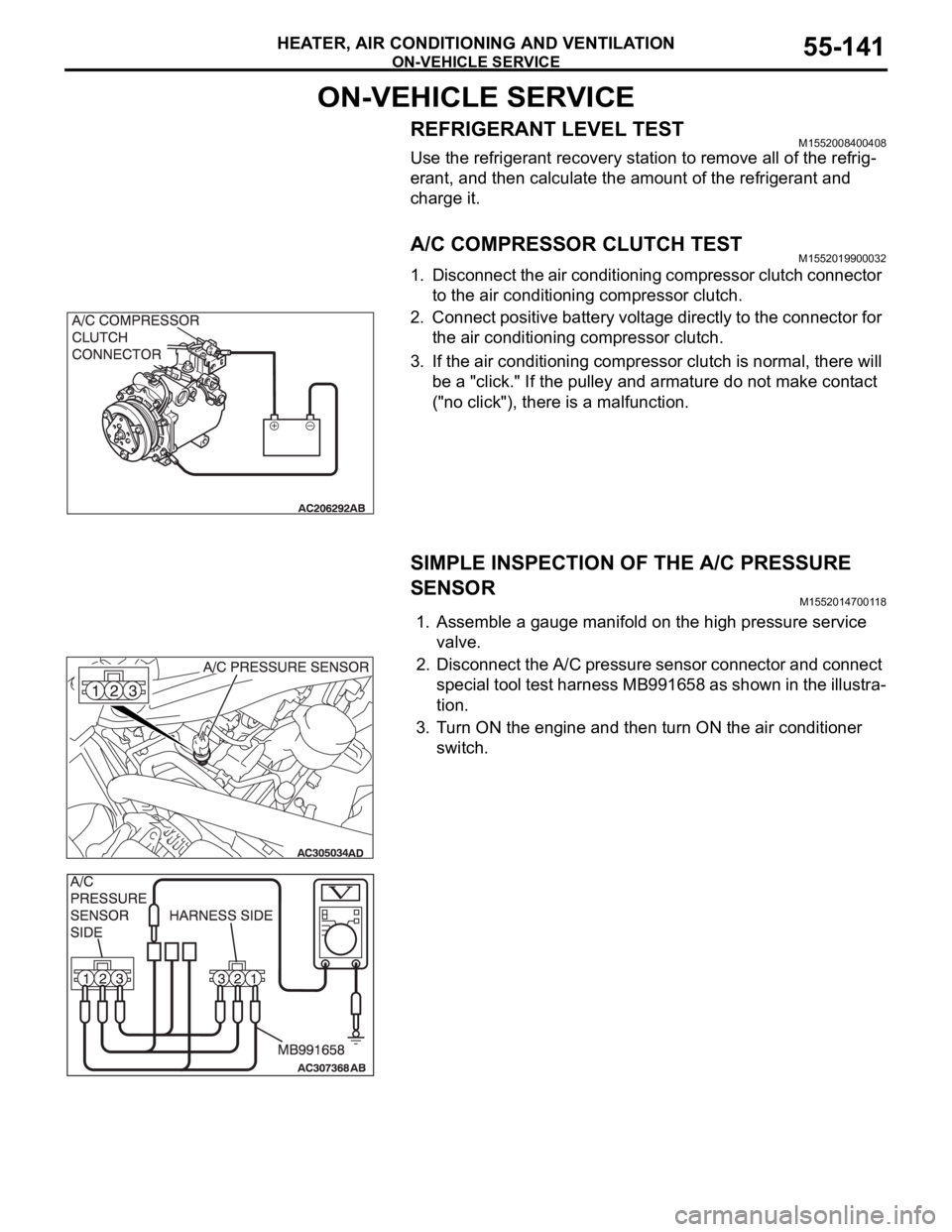
A/C COMPRESSOR CLUTCH TESTM1552019900032
1. Disconnect the air conditioning compressor clutch connector
to the air conditioning compressor clutch.
2. Connect positive battery voltage directly to the connector for
the air conditioning compressor clutch.
3. If the air conditioning compressor clutch is normal, there will
be a "click." If the pulley and armature do not make contact
("no click"), there is a malfunction.
SIMPLE INSPECTION OF THE A/C PRESSURE
SENSOR
M1552014700118
1. Assemble a gauge manifold on the high pressure service
valve.
2. Disconnect the A/C pressure sensor connector and connect
special tool test harness MB991658 as shown in the illustra-
tion.
3. Turn ON the engine and then turn ON the air conditioner
switch.
Page 844 of 1500
ON-VEHICLE SERVICE
HEATER, AIR CONDITIONING AND VENTILATION55-143
PERFORMANCE TEST M1552001400526
The vehicles to be tested should be parked out of direct sun-
light.
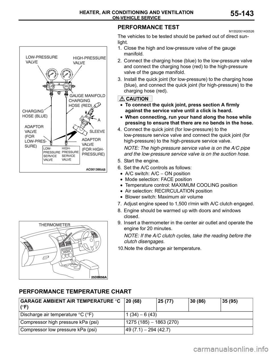
1. Close the high and low-pressure valve of the gauge
manifold.
2. Connect the charging hose (blue) to the low-pressure valve
and connect the charging hose (red) to the high-pressure
valve of the gauge manifold.
3. Install the quick joint (for low-pressure) to the charging hose
(blue), and connect the quick joint (for high-pressure) to the
charging hose (red).
To connect the quick joint, press section A firmly
against the service valve until a click is heard.
When connecting, run your hand along the hose while
pressing to ensure that there are no bends in the hose.
4. Connect the quick joint (for low-pressure) to the
low-pressure service valve and connect the quick joint (for
high-pressure) to the high-pressure service valve.
NOTE: The high-pressure service valve is on the A/C pipe
and the low-pressure service valve is on the suction hose.
5. Start the engine.
6. Set the A/C controls as follows:
A/C switch: A/C ON position
Mode selection: FACE position
Temperature control: MAXIMUM COOLING position
Air selection: RECIRCULATION position
Blower switch: Maximum air volume
7. Adjust engine speed to 1,500 r/min with A/C clutch engaged.
8. Engine should be warmed up with doors and windows
closed.
9. Insert a thermometer in the center air outlet and operate the
engine for 20 minutes.
NOTE: If the A/C clutch cycles, take the reading before the
clutch disengages.
10.Note the discharge air temperature.
PERFORMANCE TEMPERATURE CHART
GARAGE AMBIENT AIR TEMPERATURE C
(
F)20 (68) 25 (77) 30 (86) 35 (95)
Discharge air temperature
C (F) 1 (34) 6 (43)
Compressor high pressure kPa (psi) 1275 (185)
1863 (270)
Compressor low pressure kPa (psi) 49 (7.1)
294 (42.7)
Page 847 of 1500

ON-VEHICLE SERVICE
HEATER, AIR CONDITIONING AND VENTILATION55-146
Sharper bends will reduce the flow of refrigerant. The flexible
hose lines should be routed so that they are at least 80 mm
(3.1 inches) from the exhaust manifold. It is good practice to
inspect all flexible hose lines at least once a year to make sure
they are in good condition and properly routed.
On standard plumbing fittings with O-rings, these O-rings are
not reusable.
AIR CONDITIONING NOISE TEST
You must first know the conditions when the noise occurs.
These conditions are: weather, vehicle speed, in gear or neu-
tral, engine temperature or any other special conditions.
Noises that develop during A/C operation can often be mislead-
ing. For example: what sounds like a failed front bearing or
connecting rod, may be caused by loose bolts, nuts, mounting
brackets, or a loose clutch assembly. Verify accessory drive
belt tension (power steering or generator).
Improper accessory drive belt tension can cause a misleading
noise when the compressor is engaged and little or no noise
when the compressor is disengaged.
Drive belts are speed-sensitive. That is, at different engine
speeds, and depending upon belt tension, belts can develop
unusual noises that are often mistaken for mechanical prob-
lems within the compressor.
Normal air conditioning operation will generate some level of
operational noise. To judge what is normal and abnormal,
requires an understanding of the air conditioning system. This
test is to detail the most common noise complaints and the
repair methods.
VEHICLE CONDITION
1. Ensure the system is not over or under charged.(Refer to
P.55-142).
2. Tighten all compressor mounting bolts, clutch mounting
bolts and compressor drive belt.
3. Inspect layout of the system is correct, ie no interference
between hoses and all retaining clamps are in place.
Page 849 of 1500
ON-VEHICLE SERVICE
HEATER, AIR CONDITIONING AND VENTILATION55-148
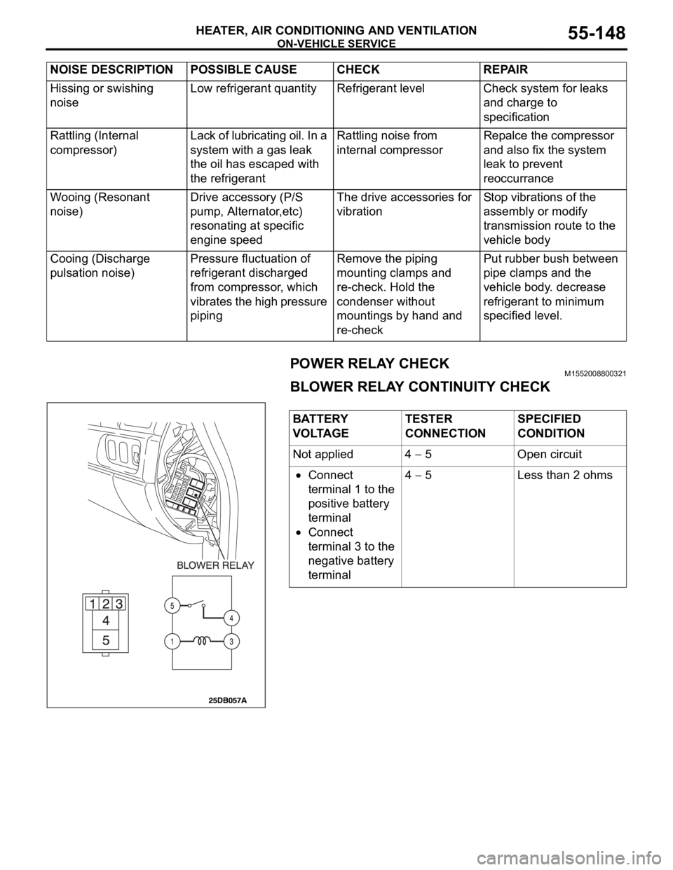
POWER RELAY CHECKM1552008800321
BLOWER RELAY CONTINUITY CHECK
Hissing or swishing
noiseLow refrigerant quantity Refrigerant level Check system for leaks
and charge to
specification
Rattling (Internal
compressor)Lack of lubricating oil. In a
system with a gas leak
the oil has escaped with
the refrigerantRattling noise from
internal compressorRepalce the compressor
and also fix the system
leak to prevent
reoccurrance
Wooing (Resonant
noise)Drive accessory (P/S
pump, Alternator,etc)
resonating at specific
engine speedThe drive accessories for
vibrationStop vibrations of the
assembly or modify
transmission route to the
vehicle body
Cooing (Discharge
pulsation noise)Pressure fluctuation of
refrigerant discharged
from compressor, which
vibrates the high pressure
pipingRemove the piping
mounting clamps and
re-check. Hold the
condenser without
mountings by hand and
re-checkPut rubber bush between
pipe clamps and the
vehicle body. decrease
refrigerant to minimum
specified level. NOISE DESCRIPTION POSSIBLE CAUSE CHECK REPAIR
BATTERY
VOLTAGETESTER
CONNECTIONSPECIFIED
CONDITION
Not applied 4
5 Open circuit
Connect
terminal 1 to the
positive battery
terminal
Connect
terminal 3 to the
negative battery
terminal4
5 Less than 2 ohms
Page 850 of 1500
ON-VEHICLE SERVICE
HEATER, AIR CONDITIONING AND VENTILATION55-149
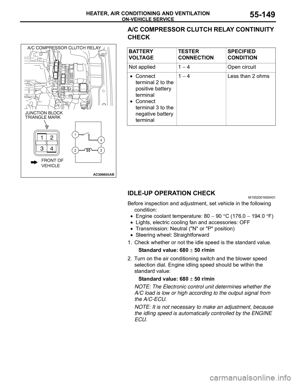
A/C COMPRESSOR CLUTCH RELAY CONTINUITY
CHECK
IDLE-UP OPERATION CHECK
M1552001600401
Before inspection and adjustment, set vehicle in the following
condition:
Engine coolant temperature: 80 90 C (176.0 194.0 F)
Lights, electric cooling fan and accessories: OFF
Transmission: Neutral ("N" or "P" position)
Steering wheel: Straightforward
1. Check whether or not the idle speed is the standard value.
Standard value: 680
50 r/min
2. Turn on the air conditioning switch and the blower speed
selection dial. Engine idling speed should be within the
standard value:
Standard value: 680
50 r/min
NOTE: The Electronic control unit determines whether the
A/C load is low or high according to the output signal from
the A/C-ECU.
NOTE: It is not necessary to make an adjustment, because
the idling speed is automatically controlled by the ENGINE
ECU. BATTERY
V O LTA G ETESTER
CONNECTIONSPECIFIED
CONDITION
Not applied 1
4 Open circuit
Connect
terminal 2 to the
positive battery
terminal
Connect
terminal 3 to the
negative battery
terminal1
4 Less than 2 ohms
Page 852 of 1500
HEATER UNIT, HEATER CORE, BLOWER ASSEMBLY AND EVAPORATOR UNIT
HEATER, AIR CONDITIONING AND VENTILATION55-151
HEATER UNIT, HEATER CORE, BLOWER ASSEMBLY AND
EVAPORATOR UNIT
REMOVAL AND INSTALLATIONM1552021400012
Before removing the front seat assembly, refer to GROUP 52B, Service Precautions
P.52B-16 and Air Bag Module and Clock Spring P.52B-237.
Pre-removal and Post-installation Operation
Refrigerant draining and Refilling (Refer to Charging and
Discharging P.55-142).
Engine coolant Draining and Refilling (Refer to GROUP
00, Engine coolant P.00-47).
Instrument Panel Removal and Installation (Refer to
GROUP 52A, Instrument Panel P.52A-4).
Steering Column Shaft Assembly Removal and Installa-
tion (Refer to GROUP 37A, Steering ShaftP.37-25).
Floor Console Removal and Installation (Refer to GROUP
52A, Floor Console P.52A-10).
Front Seat Assembly Removal and Installation (Refer to
GROUP 52A, Front Seat P.52A-21).
² Strut Tower Bar (Refer to GROUP 42, Removal And
InstallationP.42-12.)
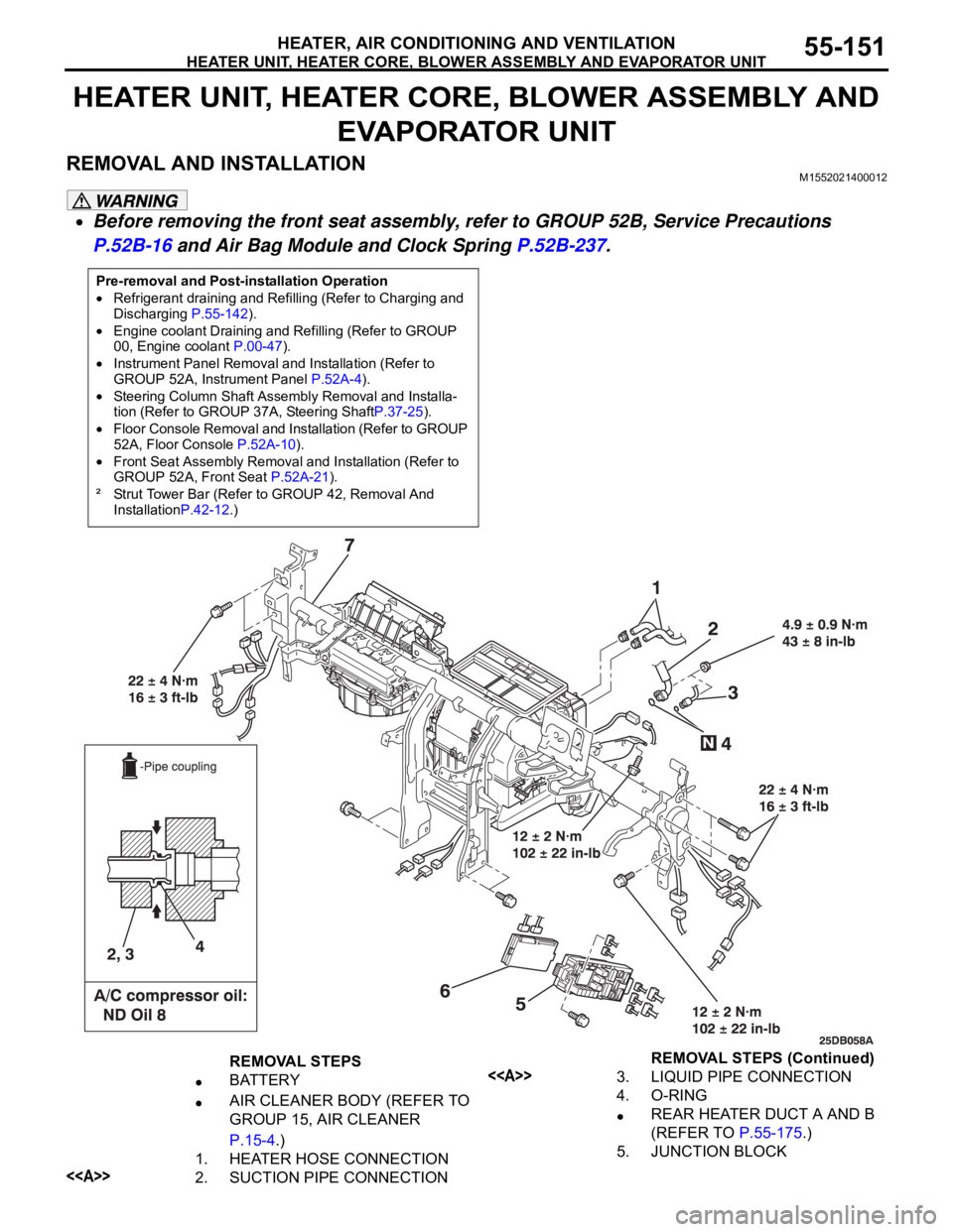
REMOVAL STEPS
BATTERY
AIR CLEANER BODY (REFER TO
GROUP 15, AIR CLEANER
P.15-4.)
1. HEATER HOSE CONNECTION
<>2. SUCTION PIPE CONNECTION
<>3. LIQUID PIPE CONNECTION
4. O-RING
REAR HEATER DUCT A AND B
(REFER TO P.55-175.)
5. JUNCTION BLOCKREMOVAL STEPS (Continued)
Page 881 of 1500
FUSIBLE LINK, FUSE AND IOD OR STORAGE CONNECTOR
COMPONENT LOCATIONS70-2
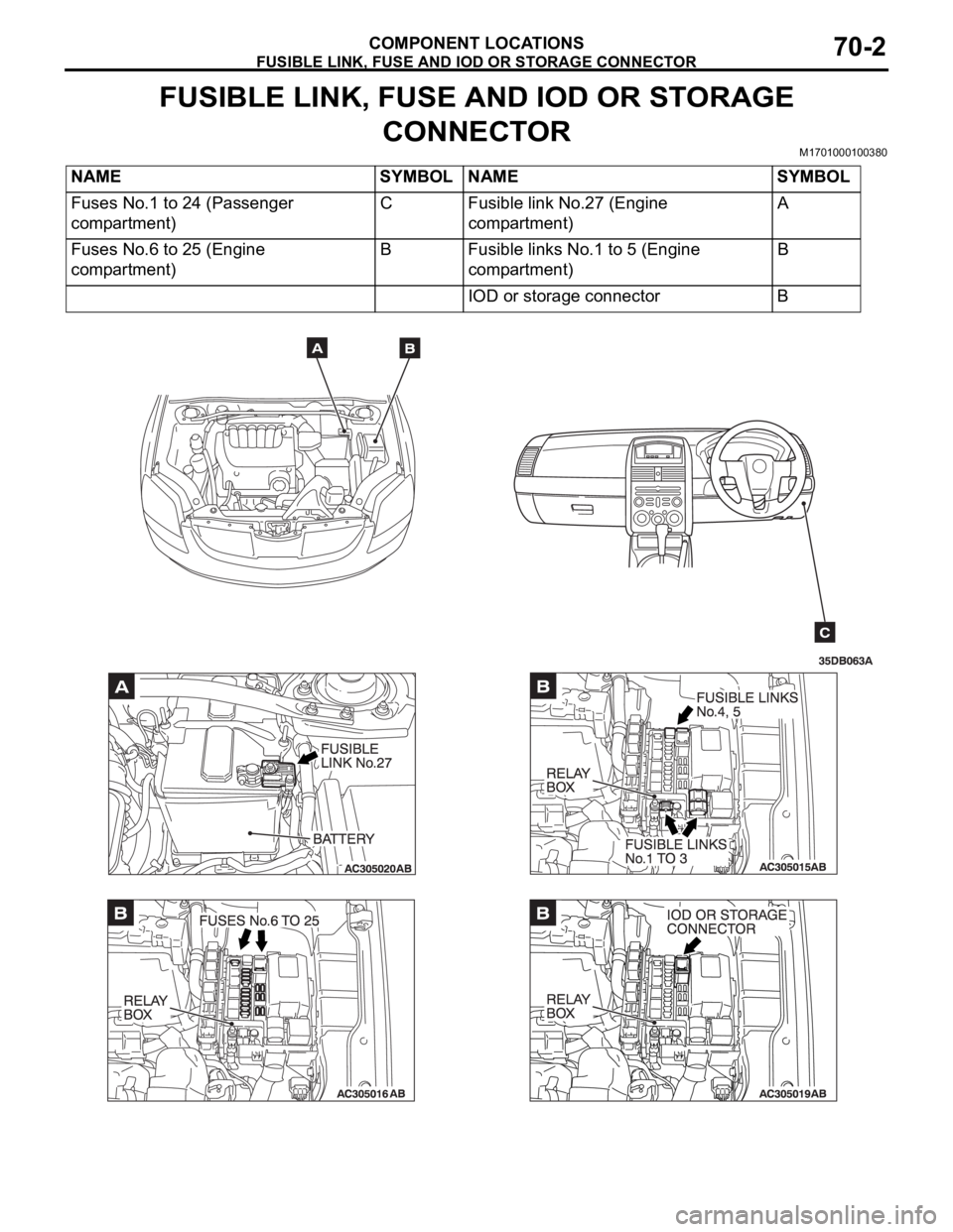
FUSIBLE LINK, FUSE AND IOD OR STORAGE
CONNECTOR
M1701000100380
NAME SYMBOL NAME SYMBOL
Fuses No.1 to 24 (Passenger
compartment)C Fusible link No.27 (Engine
compartment)A
Fuses No.6 to 25 (Engine
compartment)B Fusible links No.1 to 5 (Engine
compartment)B
IOD or storage connector B