MITSUBISHI COLT 2006 Service Repair Manual
Manufacturer: MITSUBISHI, Model Year: 2006, Model line: COLT, Model: MITSUBISHI COLT 2006Pages: 364, PDF Size: 11.65 MB
Page 321 of 364

CONSTRUCTION DIAGRAM
ACTIVE STABILITY CONTROL SYSTEM (ASC)35C-11
C1371Yaw rate sensor signal
errorEnabledEnabledProhibitedProhibitedProhibitedProhibited
C1385Yaw rate sensor error
C1387Lateral G-sensor errorEnabledEnabledProhibitedProhibitedProhibitedProhibited
C1388Yaw rate sensor active
check errorEnabledEnabledProhibitedProhibitedProhibitedEnabled
C1394Steering wheel sensor
neutral point not learnedEnabledEnabledProhibitedProhibitedProhibitedProhibited
C1396Engine torque
intervention rejectionEnabledEnabledProhibitedProhibitedProhibitedProhibited
C1505Steering wheel sensor
malfunction (detection at
the ASC-ECU side)EnabledEnabledProhibitedProhibitedProhibitedProhibited
C1555Range exceeding of
steering wheel sensor
C1607Malfunction of ASC-ECUProhibitedProhibitedProhibitedProhibitedProhibitedProhibited
ASC-ECU malfunction
(CAN communication
circuit failure)EnabledEnabledProhibitedProhibitedProhibitedProhibited
C1621G and yaw rate sensor
improper installationEnabledEnabledProhibitedProhibitedProhibitedProhibited
C1860Abnormal rise of
ASC-ECU power supply
voltageProhibitedProhibitedProhibitedProhibitedProhibitedProhibited
C1861Abnormal drop of
ASC-ECU power supply
voltageProhibitedEnabledProhibitedProhibitedProhibitedProhibited
C1862Abnormal power supply
voltage of G and yaw rate
sensor (high voltage)EnabledEnabledProhibitedProhibitedProhibitedProhibited
C1863Abnormal power supply
voltage of G and yaw rate
sensor (low voltage)
U1073Bus-offEnabledEnabledProhibitedProhibitedProhibitedProhibited
U1100Engine-related CAN
time-out errorEnabledEnabledProhibitedProhibitedProhibitedProhibited
U1104Steering wheel sensor
CAN time-out errorEnabledEnabledProhibitedProhibitedProhibitedProhibited
U1105G and yaw rate sensor
CAN time-out errorEnabledEnabledProhibitedProhibitedProhibitedProhibited
U1406Accelerator pedal position
signal errorEnabledEnabledProhibitedProhibitedProhibitedProhibited
U1426Engine speed signal errorEnabledEnabledProhibitedProhibitedProhibitedProhibited
U1427Engine torque signal errorEnabledEnabledProhibitedProhibitedProhibitedProhibited
Diagnosis
code No.Item ABS EBD TCL ASC
Engine
controlBrake
controlEngine
controlBrake
control
Page 322 of 364

CONSTRUCTION DIAGRAM
ACTIVE STABILITY CONTROL SYSTEM (ASC)35C-12
Indicator lamp
U1428Engine's maximum torque
signal errorEnabledEnabledProhibitedProhibitedProhibitedProhibited
U1429Engine's minimum torque
signal errorEnabledEnabledProhibitedProhibitedProhibitedProhibited
U1430Engine torque request
signal errorEnabledEnabledProhibitedProhibitedProhibitedProhibited
Diagnosis
code No.Item ABS EBD TCL ASC
Engine
controlBrake
controlEngine
controlBrake
control
Diagnosis
code No.ItemBrake warning
lampABS warning lampActive stability
control system
(ASC) indicator
lamp ASC OFF indicator
lamp
C1200Wheel speed sensor
(FR) system (open or
short to earth or power
supply)Illuminates when
three wheels or
more are
abnormal.IlluminatesIlluminatesIlluminates
C1205Wheel speed sensor
(FL) system (open or
short to earth or power
supply)
C1210Wheel speed sensor
(RR) system (open or
short to earth or power
supply)
C1215Wheel speed sensor
(RL) system (open or
short to earth or power
supply)
C1201Wheel speed sensor
(FR) system (sensor
transmitting error)Illuminates when
three wheels or
more are
abnormal.IlluminatesIlluminatesIlluminates
C1206Wheel speed sensor
(FL) system (sensor
transmitting error)
C1211Wheel speed sensor
(RR) system (sensor
transmitting error)
C1216Wheel speed sensor
(RL) system (sensor
transmitting error)
C1222Wheel sensor system
(abnormal power
supply voltage)IlluminateIlluminateIlluminateIlluminate
C1225Wheel speed sensor
malfunctionIlluminatesIlluminatesIlluminatesIlluminates
Page 323 of 364

CONSTRUCTION DIAGRAM
ACTIVE STABILITY CONTROL SYSTEM (ASC)35C-13
C1226Control solenoid valve
(FR) pressure holding
systemIlluminatesIlluminatesIlluminatesIlluminates
C1231Control solenoid valve
(FR) decompressing
system
C1236Control solenoid valve
(FL) pressure holding
system
C1241Control solenoid valve
(FL) pressure reducing
system
C1246Control solenoid valve
(RR) pressure holding
system
C1251Control solenoid valve
(RR) pressure
reducing system
C1256Control solenoid valve
(RL) pressure holding
system
C1261Control solenoid valve
(RL) decompressing
system
C1266Pump motor rotation
malfunction OffIlluminatesIlluminatesIlluminates
C1273Pump motor drive
circuit malfunction
C1274Pump motor drive
circuit stuck on
C1276Valve relay systemIlluminatesIlluminatesIlluminatesIlluminates
C1278Valve relay stuck off
C1279Valve relay stuck on IlluminatesIlluminatesIlluminatesIlluminates
C1300Front-right cut valve
(Primary)IlluminatesIlluminatesIlluminatesIlluminates
C1305Front-right suction
valve (Primary)
C1310Front-left cut valve
(secondly)
C1315Front-left suction valve
(secondly)
C1340Abnormal stop lamp
switch signalOffIlluminatesIlluminatesIlluminates
C1345Low brake fluid levelIlluminatesOffOffOff
Diagnosis
code No.Item Brake warning
lampABS warning lamp Active stability
control system
(ASC) indicator
lamp ASC OFF indicator
lamp
Page 324 of 364

CONSTRUCTION DIAGRAM
ACTIVE STABILITY CONTROL SYSTEM (ASC)35C-14
C1364Brake fluid Pressure
sensor malfunctionOffIlluminatesIlluminatesIlluminates
C1366Lateral G sensor signal
malfunctionOffOffIlluminatesIlluminates
C1371Yaw rate sensor signal
malfunctionOffOffIlluminatesIlluminates
C1385Yaw rate sensor
malfunction
C1387Lateral G-sensor
malfunctionOffOffIlluminatesIlluminates
C1388Yaw rate sensor active
check error
C1394Steering wheel sensor
neutral point not
learnedOffOffIlluminatesIlluminates
C1396Active stability control
system control
temporarily disabled
(engine torque request
rejected)OffOffIlluminatesIlluminates
C1505Steering wheel sensor
abnormality (detected
at ABS/active stability
control
system-ECU-side)OffOffIlluminatesIlluminates
C1555Output error in steering
wheel sensor
C1607Defective active
stability control
system-ECUIlluminatesIlluminatesIlluminatesIlluminates
C1621G and yaw rate sensor
improper installationOffOffIlluminateIlluminate
C1860ABS/Active stability
control system-ECU
power supply voltage
malfunction (high
voltage) IlluminatesIlluminatesIlluminatesIlluminates
C1861ABS/Active stability
control system-ECU
power supply voltage
malfunction (low
voltage) IlluminatesIlluminatesIlluminatesIlluminates
C1862G and yaw rate sensor
power supply voltage
malfunction (high
voltage) OffOffIlluminatesIlluminates
Diagnosis
code No.Item Brake warning
lampABS warning lamp Active stability
control system
(ASC) indicator
lamp ASC OFF indicator
lamp
Page 325 of 364

CONSTRUCTION DIAGRAM
ACTIVE STABILITY CONTROL SYSTEM (ASC)35C-15
C1863G and yaw rate sensor
power supply voltage
malfunction (low
voltage) OffOffIlluminatesIlluminates
U1073Bus-offIlluminatesIlluminatesIlluminatesIlluminates
U1100Engine-related CAN
Timeout errorOffOffIlluminatesIlluminates
U1104Steering wheel sensor
CAN Timeout errorOffOffIlluminatesIlluminates
U1105G and yaw rate sensor
time-outOffOffIlluminatesIlluminates
U1406Failure information on
engine-A-M/T-ECU
(related to engine)OffOffIlluminatesIlluminates
U1426Failure information on
engine-A-M/T-ECU
(related to engine)OffOffIlluminatesIlluminates
U1427Failure information on
engine-A-M/T-ECU
(related to engine)
U1428Failure information on
engine-A-M/T-ECU
(related to engine)
U1429Failure information on
engine-A-M/T-ECU
(related to engine)
U1430Failure information on
engine-A-M/T-ECU
(related to engine)
Diagnosis
code No.Item Brake warning
lampABS warning lamp Active stability
control system
(ASC) indicator
lamp ASC OFF indicator
lamp
Page 326 of 364

CONSTRUCTION DIAGRAM
ACTIVE STABILITY CONTROL SYSTEM (ASC)35C-16
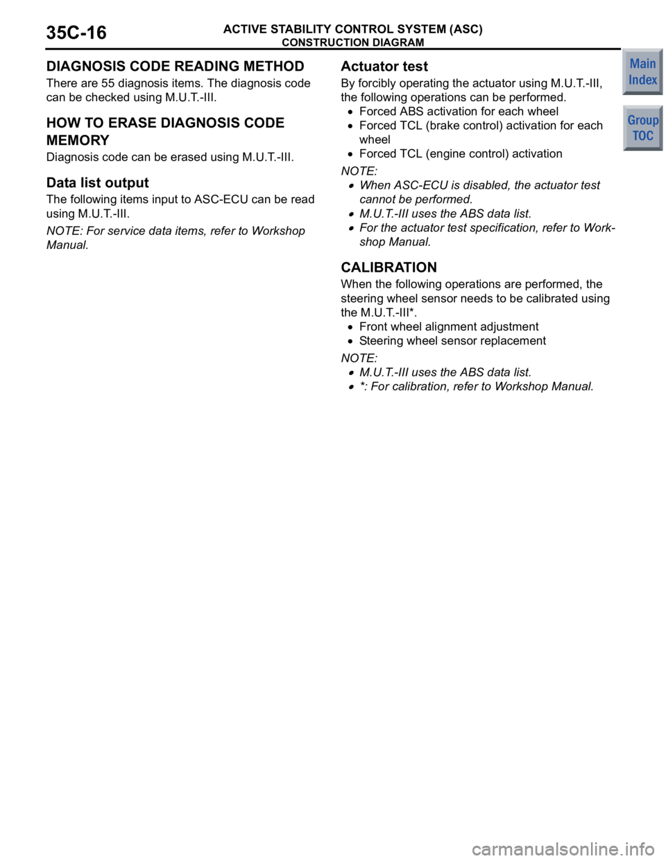
DIAGNOSIS CODE READING METHOD
There are 55 diagnosis items. The diagnosis code
can be checked using M.U.T.-III.
HOW TO ERASE DIAGNOSIS CODE
MEMORY
Diagnosis code can be erased using M.U.T.-III.
Data list output
The following items input to ASC-ECU can be read
using M.U.T.-III.
NOTE: For service data items, refer to Workshop
Manual.
Actuator test
By forcibly operating the actuator using M.U.T.-III,
the following operations can be performed.
•Forced ABS activation for each wheel
•Forced TCL (brake control) activation for each
wheel
•Forced TCL (engine control) activation
NOTE: .
•When ASC-ECU is disabled, the actuator test
cannot be performed.
•M.U.T.-III uses the ABS data list.
•For the actuator test specification, refer to Work-
shop Manual.
CALIBRATION
When the following operations are performed, the
steering wheel sensor needs to be calibrated using
the M.U.T.-III*.
•Front wheel alignment adjustment
•Steering wheel sensor replacement
NOTE: .
•M.U.T.-III uses the ABS data list.
•*: For calibration, refer to Workshop Manual.
Page 327 of 364

DESCRIPTION OF CONSTRUCTION AND OPERATION
ACTIVE STABILITY CONTROL SYSTEM (ASC)35C-17
DESCRIPTION OF CONSTRUCTION AND OPERATION
M2357000600037
Stability control operation
•ASC-ECU receives various kinds of information
from the wheel speed sensor, steering wheel
sensor, G and yaw rate sensor, pressure sensor,
stop lamp switch, brake fluid level switch, parking
brake switch, and engine ECU. When ECU deter
-
mines the vehicle runs in the oversteer or unders-
teer direction based on the signal sent from these
sensors, ASC-ECU drives each valve and pump
motor and controls the braking force to be applied
to the wheels.
•When the system increases the fluid pressure
automatically, it closes the cut valve to shut off
the pressure line to the suction valve, and drives
the pump motor. For example, when the vehicle
runs in the oversteer direction while turning to the
right, ASC-ECU supplies the brake fluid from the
pump to the front left wheel in order to apply the
braking force on it.
•ASC-ECU and the engine ECU communicate
with each other via CAN communication. When
the accelerator pedal is depressed too far, the
signal requesting the engine output reduction is
sent to the engine ECU so that the ASC controlla
-
bility can be secured.
Page 328 of 364

DESCRIPTION OF CONSTRUCTION AND OPERATION
ACTIVE STABILITY CONTROL SYSTEM (ASC)35C-18
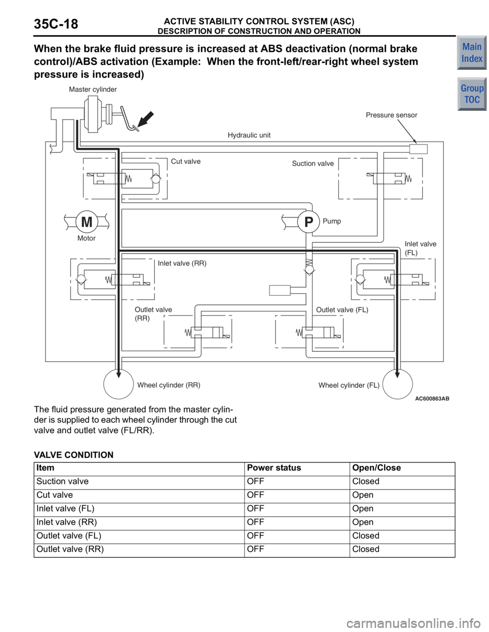
When the brake fluid pressure is increased at ABS deactivation (normal brake
control)/ABS activation (Example: When the front-left/rear-right wheel system
pressure is increased)
AC600863 AB
MP
Master cylinder
Cut valve
Motor Inlet valve (RR)
Outlet valve
(RR)
Wheel cylinder (RR) Hydraulic unit
Pressure sensor
Suction valve
Pump Inlet valve
(FL)
Outlet valve (FL)
Wheel cylinder (FL)
The fluid p r essure ge nerated from the maste r cylin-
de r is supplied to each wheel cylinder through the cut
valve an
d outlet valve (FL/RR).
VA L VE CONDITION
ItemPower statusOpen/Close
Suction valveOFFClosed
Cut valveOFFOpen
Inlet valve (FL)OFFOpen
Inlet valve (RR)OFFOpen
Outlet valve (FL)OFFClosed
Outlet valve (RR)OFFClosed
Page 329 of 364

DESCRIPTION OF CONSTRUCTION AND OPERATION
ACTIVE STABILITY CONTROL SYSTEM (ASC)35C-19
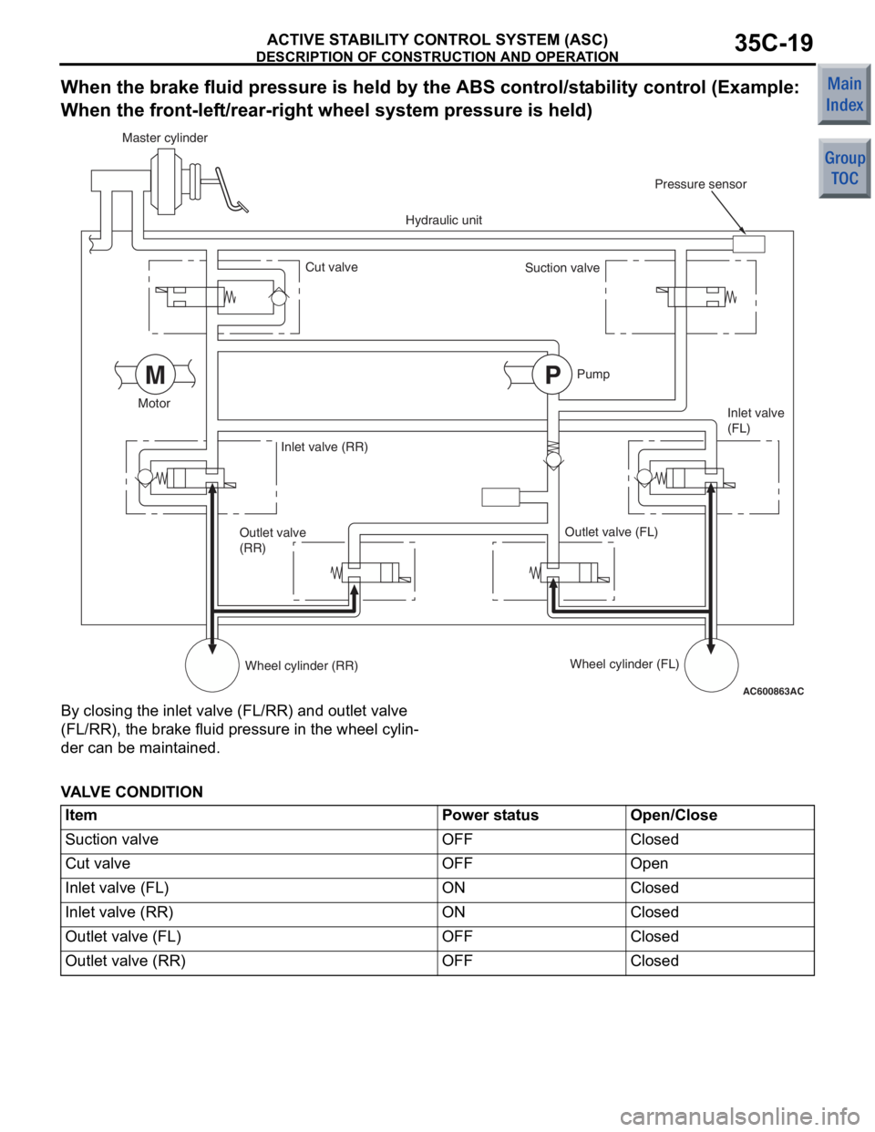
When the brake fluid pressure is held by the ABS control/stability control (Example:
When the front-left/rear-right whee l system pressure is held)
AC600863
AC
MP
Master cylinder
Cut valve
Motor Inlet valve (RR)
Outlet valve
(RR)
Wheel cylinder (RR) Hydraulic unit
Pressure sensor
Suction valve
Pump Inlet valve
(FL)
Outlet valve (FL)
Wheel cylinder (FL)
By closing the inlet va lve (FL/RR) and o u tle t valve
(FL/RR), the br
ake f l uid pressure in the wh eel cylin
-
der can be main t a ined.
VA L VE CONDITION
ItemPower statusOpen/Close
Suction valveOFFClosed
Cut valveOFFOpen
Inlet valve (FL)ONClosed
Inlet valve (RR)ONClosed
Outlet valve (FL)OFFClosed
Outlet valve (RR)OFFClosed
Page 330 of 364

DESCRIPTION OF CONSTRUCTION AND OPERATION
ACTIVE STABILITY CONTROL SYSTEM (ASC)35C-20
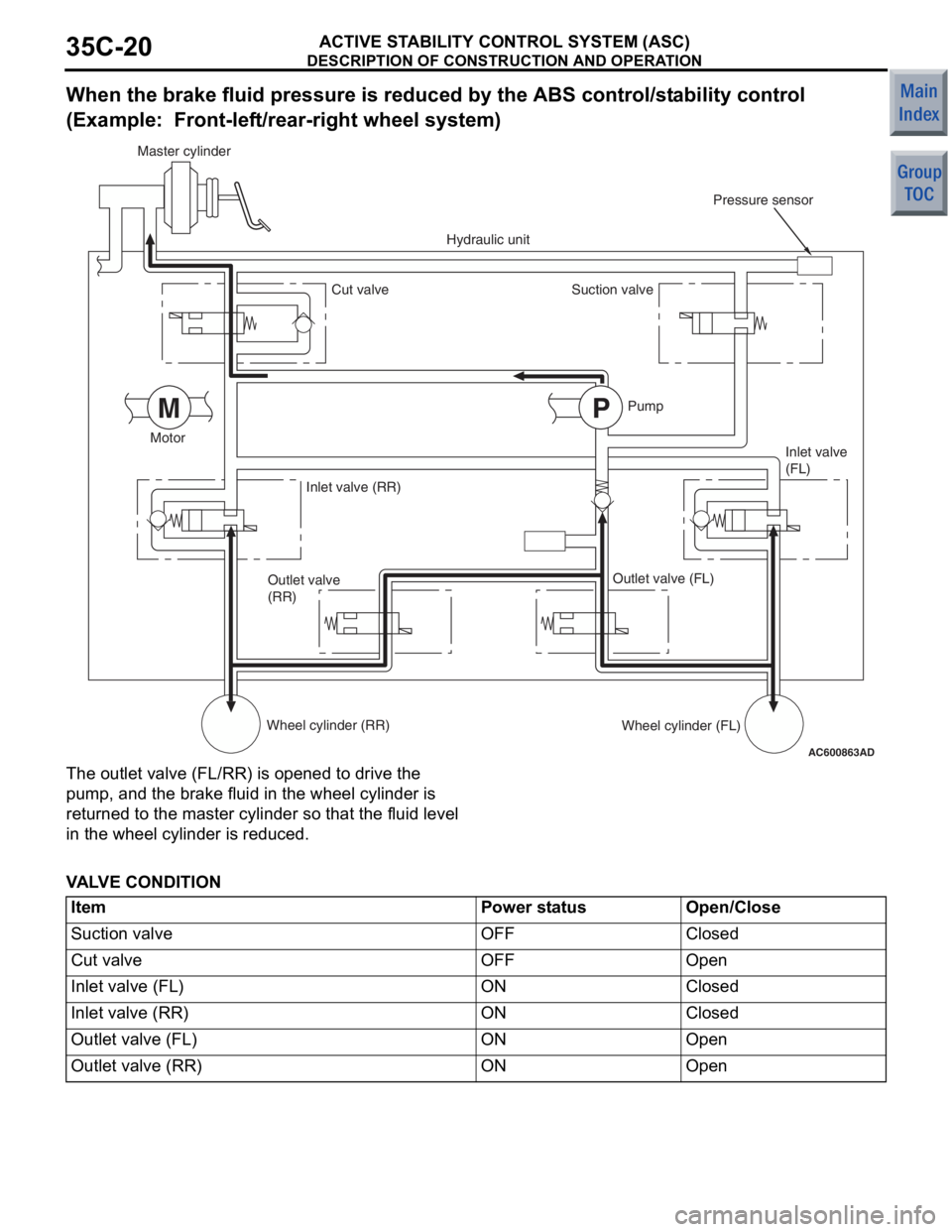
When the brake fluid pressure is reduced by the ABS control/stability control
(Example: Front-left/rear-right wheel system)
AC600863 AD
MP
Master cylinder
Cut valve
Motor Inlet valve (RR)
Outlet valve
(RR)
Wheel cylinder (RR) Hydraulic unit
Pressure sensor
Suction valve
Pump Inlet valve
(FL)
Outlet valve (FL)
Wheel cylinder (FL)
The out let valve (FL/RR) is ope ned to drive the
pump
, and th e brake fluid in the wh eel cylinde r is
returned
to the master cylinder so tha t the fluid level
in the
wheel cylinde r is reduced.
VA L VE CONDITION
ItemPower statusOpen/Close
Suction valveOFFClosed
Cut valveOFFOpen
Inlet valve (FL)ONClosed
Inlet valve (RR)ONClosed
Outlet valve (FL)ONOpen
Outlet valve (RR)ONOpen