lock MITSUBISHI ECLIPSE 1991 Service Manual
[x] Cancel search | Manufacturer: MITSUBISHI, Model Year: 1991, Model line: ECLIPSE, Model: MITSUBISHI ECLIPSE 1991Pages: 1216, PDF Size: 67.42 MB
Page 272 of 1216
7-24COOLING - Water Pump <2.0L DOHC Engine>
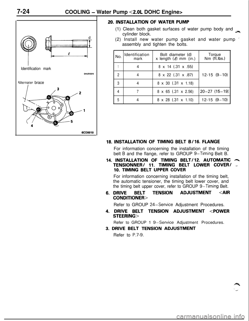
Identification mark
4lternater brace
6COOOlO
20. INSTALLATION OF WATER PUMP
(1) Clean both gasket surfaces of water pump body and
jir,cylinder block.
(2) Install new water pump gasket and water pump ’
assembly and tighten the bolts.
No, IdentificationBolt diameter (d)Torquemarkx length (I?) mm (in.)Nm (ft.lbs.1
148x14(.31x.55)
248x22(.31x.87)12-15(g-10)
348x30(.31x1.18)
4
78x65(.31x2.56)20-27(15-191
548x28(.31x1.10)12-15(g-10)
18. INSTALLATION OF TIMING BELT B/16. FLANGEFor information concerning the installation of the timing
belt
B and the flange, refer to GROUP g-Timing Belt B.
14. INSTALLATION OF TIMING BELT/lZ. AUTOMATIC 6TENSlONNER/
11. TIMING BELT LOWER COVER/ -
10. TIMING BELT UPPER COVERFor information concerning installation of the timing belt,
the automatic tensioner, the timing belt lower cover, and
the timing belt upper cover, refer to GROUP g-Timing Belt.
6. DRIVEBELT TENSIONADJUSTMENT
Refer to GROUP
24-Service Adjustment Procedures.
4. DRIVE BELT TENSION ADJUSTMENT
Refer to GROUP 1
g-Service Adjustment Procedures.
3. DRIVE BELT TENSION ADJUSTMENT
Refer to
P.7-9.
Page 273 of 1216
COOLING - Water Hose and Water Pipe <1.8L Engine>
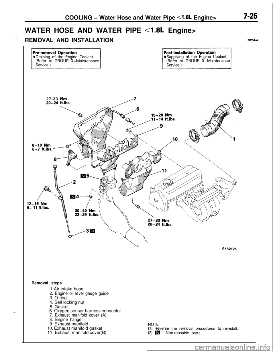
WATER HOSE AND WATER PIPE
<1.8L Engine>
_-REMOVAL AND INSTALLATIONNO’IIA-A27-33 Nm
20-24 ftlbs.
12-15 Nms- 11 ft.lbs.Removal steps
1 Air intake hose
2. Engine oil level gauge guide3. O-ring
4. Self locking nut
5. Gasket
6. Oxygen sensor harness connector
7. Exhaust manifold cover (A)
8. Engine hanger9. Exhaust manifold
IO. Exhaust manifold gasket
11. Exhaust manifold cover(B)NOTE(1) Reverse the removal procedures to reinstall.(2) m : Non-reusable parts
Page 276 of 1216
7-28COOLING- Water Hose and Water Pipe <2.0L DOHC Engine (Non-Turbo)>
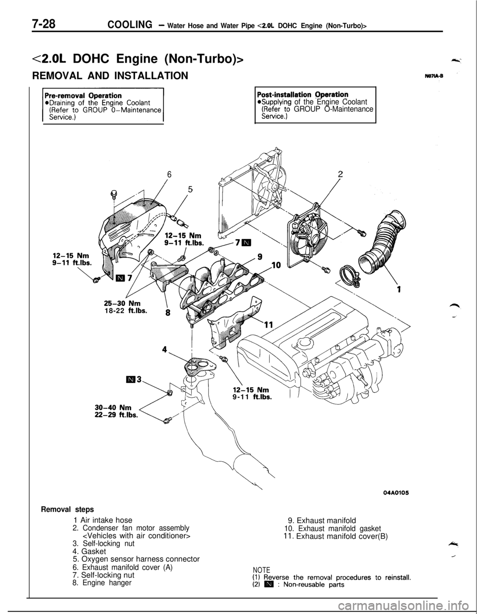
<2.0L DOHC Engine (Non-Turbo)>
REMOVAL AND INSTALLATION
Post-installgtion Pperation@Supplying of the Engine Coolant(FF$efeet; GROUP O-Maintenance
6
/5
/l--5ia
225-30 Nm
18-22
ft.lbs.
12-1s Nrn9-11 ft.lbs.
Removal steps1 Air intake hose
2. Condenser fan motor assembly
3. Self-locking nut4. Gasket
5. Oxygen sensor harness connector
6. Exhaust manifold cover (A)7. Self-locking nut
8. Engine hanger
04A01059. Exhaust manifold
10. Exhaust manifold gasket11. Exhaust manifold cover(B)
NOTE(1) Reverse the removal procedures to reinstall.(21 m : Non-reusable parts
Page 279 of 1216
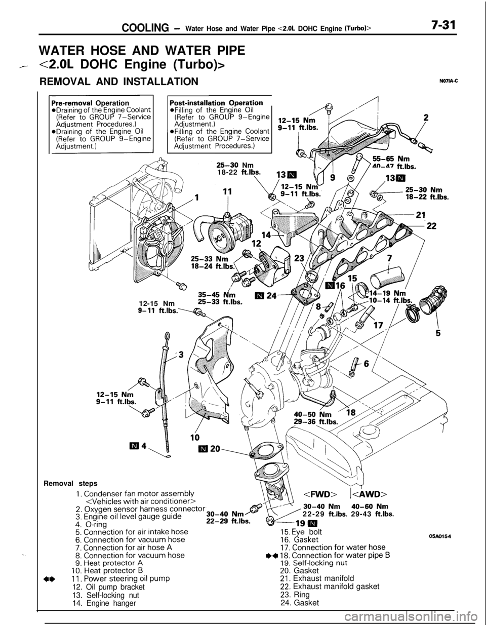
COOLING -Water Hose and Water Pipe <2.0L DOHC Engine (Turbo)>7-31WATER HOSE AND WATER PIPE
7--<2.0L DOHC Engine (Turbo)>
REMOVAL AND INSTALLATION
N071A-C
. .
ation OperationPost-installi@Filling of the Engine Oil(Refer to GROUP g-EngineaFilling of the
Engine Coolant(Refer to GROUP 7-ServiceAdjustment Procedures.)
Pre-removal OperationeDraining of the Engine Coolant(Refer to GROUP 7-ServiceAdjustment Procedures.)*Draining of the Engine Oil(Refer to GROUP g-Engine
25-30 Nm
18-22 ftlbs.4n-47 ft.lbs.
w35-45 N/m12-15 Nm25-33 ft.lbs.
9- 11ft.lbs.----Q&Removal steps
1. Condenser fan motor assembly
4*11. Power steering oil pump
12. Oil pump bracket
13. Self-locking nut
14. Engine hanger22-29
ft.lbs. 29-43 ft.lbs.
15. Eye bolt16. Gasket17. Connection for water hose
I)+ 18. Connection for water pipe B19. Self-locking nut20. Gasket21. Exhaust manifold22. Exhaust manifold gasket
23. Ring
24. Gasket
05m154
Page 285 of 1216
9-1
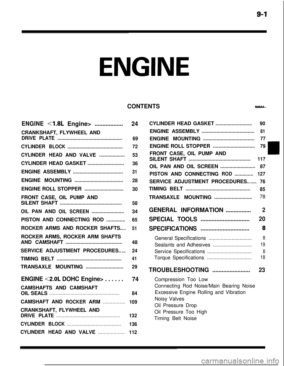
ENGINE
CONTENTSNOSAA-
ENGINE<1.8L
Engine>..................
24CRANKSHAFT, FLYWHEEL AND
DRIVE PLATE................................................
69
CYLINDER
BLOCK.........................................72
CYLINDERHEADANDVALVE
...................
53CYLINDER HEAD GASKET
...........................
36ENGINE ASSEMBLY
.....................................31ENGINE MOUNTING
....................................
28ENGINE ROLL STOPPER
.............................
30FRONT CASE, OIL PUMP AND
SILENT SHAFT
..............................................
58
OILPANANDOILSCREEN........................34
PISTON AND CONNECTING ROD
..............
65ROCKER ARMS AND ROCKER SHAFTS..
..51ROCKER ARMS, ROCKER ARM SHAFTS
AND CAMSHAFT
..........................................48
SERVICE ADJUSTMENT PROCEDURES..
...24TIMING BELT
................................................41TRANSAXLE MOUNTING
............................
29
ENGINE <2.0L DOHC Engine> . . . . . .
74CAMSHAFTS AND CAMSHAFT
OIL SEALS
. . . . . . . . . . . . . . . . . . . . . . . . . . . . . . . . . . . . . . . . . . . . . . . . . . . . .84CAMSHAFTAND
ROCKERARM. . . . . . . . . . . . . . . .109CRANKSHAFT, FLYWHEEL AND
DRIVE PLATE. . . . . . . . . . . . . . . . . . . . . . . . . . . . . . . . . . . . . . . . . . . . . . . .132
CYLINDERBLOCK. . . . . . . . . . . . . . . . . . . . . . . . . . . . . . . . . . . . . . . . .136
CYLINDERHEADANDVALVE
. . . . . . . . . . . . . . . . . . .112CYLINDER HEAD GASKET
...........................90ENGINE ASSEMBLY
.......................................81ENGINE MOUNTING
......................................77ENGINE ROLL STOPPER
...............................
79FRONT CASE, OIL PUMP AND
SILENT SHAFT
..............................................117OIL PAN AND OIL SCREEN
..........................
87
PISTONANDCONNECTING
ROD..............127SERVICE ADJUSTMENT PROCEDURES..
.....76TIMING BELT
................................................
85TRANSAXLE MOUNTING
............................78
GENERALINFORMATION................2
SPECIAL TOOLS...............................20
SPECIFICATIONS...............................8General Specifications
................................8Sealants and Adhesives
.............................19Service Specifications
.................................8Torque Specifications
.................................18
TROUBLESHOOTING........................23Compression Too Low
Connecting Rod Noise/Main Bearing Noise
Excessive Engine Rolling and Vibration
Noisy Valves
Oil Pressure Drop
Oil Pressure Too High
Timing Belt Noise
Page 292 of 1216
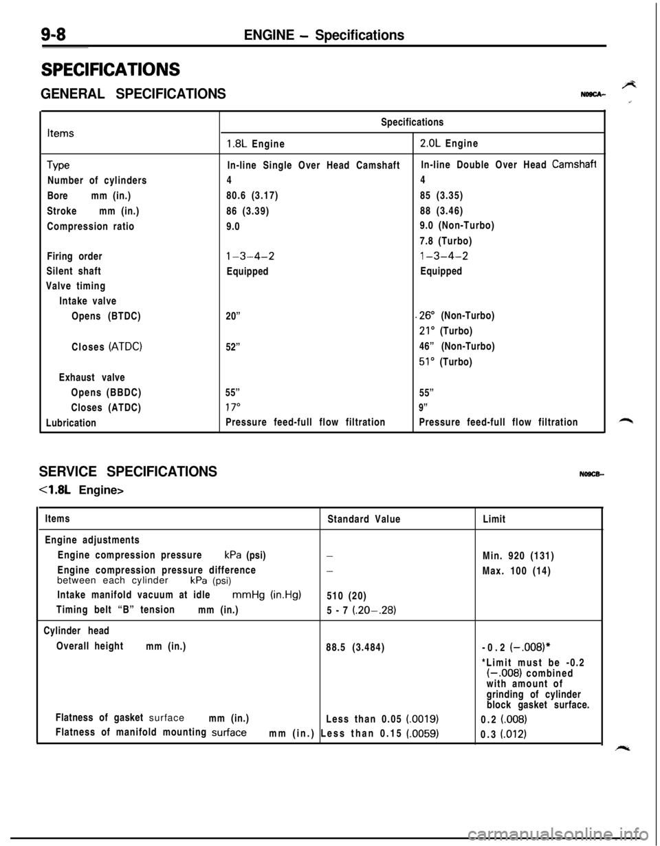
9-8ENGINE - Specifications
SPECIFICATIONS
GENERAL SPECIFICATIONSBNDBCA-
Items
TypeNumber of cylinders
Boremm (in.)
Strokemm (in.)
Compression ratio
Firing order
Silent shaft
Valve timing
Intake valve
Opens (BTDC)
Closes
(ATDC)Exhaust valve
Opens (BBDC)
Closes (ATDC)
LubricationSpecifications
1.8L Engine2.0L Engine
In-line Single Over Head CamshaftIn-line Double Over Head
Camshafi44
80.6 (3.17)85 (3.35)
86 (3.39)88 (3.46)
9.09.0 (Non-Turbo)
7.8 (Turbo)
l-3-4-21-3-4-2EquippedEquipped
20”
.26” (Non-Turbo)
21’ (Turbo)
52”46” (Non-Turbo)
51’ (Turbo)
55”
55”
17”9”Pressure feed-full flow filtrationPressure feed-full flow filtration
SERVICE SPECIFICATIONSNOSCB-
-4.8L Engine>
Items
Standard Value
Engine adjustments
Engine compression pressurekPa (psi)
-Engine compression pressure difference
-between each cylinder
kPa (psi)
Intake manifold vacuum at idle
mmHg (in.Hg)510 (20)
Timing belt “B” tension
mm (in.)
5-7
(.20-.28)Cylinder head
Overall height
mm (in.)
88.5 (3.484)
Flatness of gasket surface
mm (in.)
Less than 0.05
(0019)Flatness of manifold mounting
surfacemm (in.) Less than 0.15 (.0059)Limit
Min. 920 (131)
Max. 100 (14)
-0.2
(-.008)**Limit must be -0.2
(-.008) combined
with amount of
grinding of cylinder
block gasket surface.
0.2
(008)0.3
(.012)
Page 293 of 1216
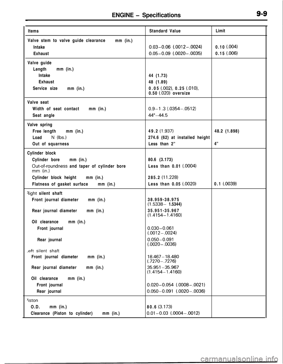
ENGINE - SpecificationsItems
Valve stem to valve guide clearance
Intake
Exhaust
Valve guide
Lengthmm (in.)
Intake
Exhaust
Service size
mm (in.)mm (in.)Standard Value
0.03-0.06 (.0012-.0024)
0.05-0.09 (.0020-.0035)44 (1.73)
48 (1.89)
0.05
(.002), 0.25 (.OlO),
0.50
i.020) oversizeLimit
0.10
f.004)0.15
i.006)Valve seat
Width of seat contactmm (in.)
Seat angle
Valve spring
Free lengthmm (in.)
Load
N (Ibs.)
Out of squarness
Cylinder block
Cylinder boremm (in.)
ZIut-of;yundness and taper of cylinder bore
Cylinder block heightmm (in.)
Flatness of gasket surfacemm (in.)qight silent shaft
Front journal diametermm (in.)
Rear journal diametermm (in.)
Oil clearancemm (in.)
Front journal
Rear journal
-eft silent shaft
Front journal diametermm (in.)
Rear journal diametermm (in.)
Oil clearancemm (in.)
Front journal
Rear journal
‘istonO.D.mm (in.)
Clearance (Piston to cylinder)mm (in.)
0.9-l .3 (.0354-.0512)
44”-44.549.2
(1.937)48.2 (1.898)
274.6 (62) at installed height
Less than 2”4”
80.6 (3.173)
Less than 0.01
(.0004)285.2
(11.228)Less than 0.05
(.0020)0.1 (.0039)38.959-38.975
(1.5338- 1.5344)
35.951-35.967
(1.4154- 1.4160)
0.030-0.061(.0012-.0024)
0.050-0.091(.0020- .0036)
18.467- 18.480(.7270- .7276)
35.951-35.967(1.4154-1.4160)
0.020-0.054 (.0008-.0021)
0.050-0.091 (.0020-.0036)80.6
(3.173)
0.01-0.03 (.0004-.0012)
Page 297 of 1216
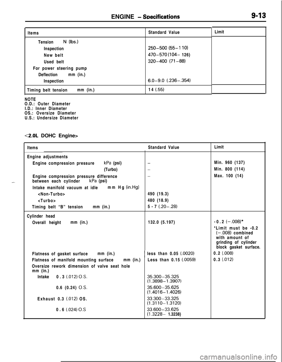
ENGINE - SDecificationsItems
TensionN (Ibs.)
Inspection
New belt
Used belt
For power steering pump
Deflectionmm (in.)
Inspection
Timing belt tensionmm (in.)Standard Value
250-500 (55-l 10)
470-570 (104- 126)
320-400 (71-88)
6.0-9.0 (.236-.354)14
(.55)NOTE
O.D.: Outer Diameter
I.D.: Inner Diameter
OS.: Oversize Diameter
U.S.: Undersize Diameter<2.0L DOHC Engine>
-ItemsStandard ValueLimit
Engine adjustments
Engine compression pressurekPa (psi)
(Turbo)
Engine compression pressure difference
between each cylinderkPa (psi)
Intake manifold vacuum at idlemm Hg
(in.Hg)
Timing belt “B” tensionmm (in.)
-
-
-490 (19.3)
480 (18.9)
5-7
(.20-.28)Cylinder head
Overall heightmm (in.)132.0 (5.197)
Flatness of gasket surfacemm (in.)
Flatness of manifold mounting surfacemm (in.)
Oversize rework dimension of valve seat hole
mm (in.)
Intake0.3
(.012) 0,s.0.6 (0.24)
0,s.Exhaust 0.3
(.012) OS.
0.6
(.024) 0.S~ less than 0.05
(.0020)Less than 0.15
(.0059)
35.300-35.325(1.3898-1.3907)
35.600-35.625
(1.4016-l .4026)
33.300-33.325(1.3110-1.3120)
33.600-33.625
(1.3228- 1.3238)Limit
Min. 960 (137)
Min. 800 (114)
Max. 100 (14)
-0.2
(-,008)”*Limit must be -0.2
(- .008) combined
with amount of
grinding of cylinder
block gasket surface.
0.2
(.008)0.3
(.012)
Page 299 of 1216
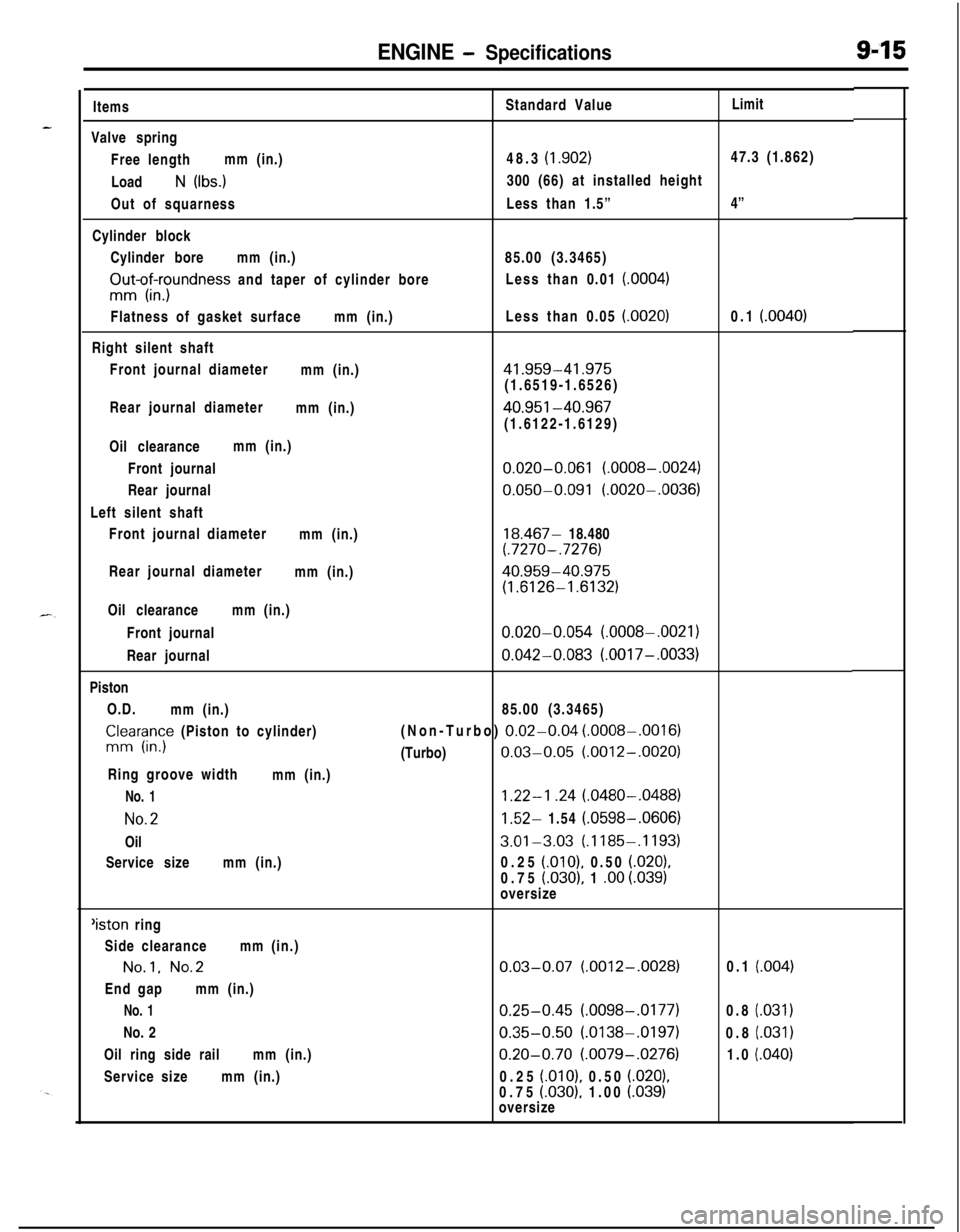
ENGINE - Specifications9-15ItemsStandard ValueLimit
Valve spring
Free lengthmm (in.)48.3
(1.902)47.3 (1.862)
Load
N (Ibs.)300 (66) at installed height
Out of squarnessLess than 1.5”4”
Cylinder block
Cylinder boremm (in.)85.00 (3.3465)
FIu-o$xrndness and taper of cylinder boreLess than 0.01 (0004)Flatness of gasket surfacemm (in.)Less than 0.05
(.0020)0.1 (.0040)Right silent shaft
Front journal diameter
mm (in.)
41.959-41.975(1.6519-1.6526)
Rear journal diameter
mm (in.)
40.951-40.967(1.6122-1.6129)
Oil clearancemm (in.)
Front journal
0.020-0.061 (.0008-.0024)Rear journal
0.050-0.091 (.0020-.0036)Left silent shaft
Front journal diameter
mm (in.)
18.467- 18.480(.7270-.7276)Rear journal diameter
mm (in.)
40.959-40.975
(1.6126-1.6132)Oil clearancemm (in.)
Front journal
0.020-0.054 (.0008-.0021)Rear journal
0.042-0.083 (.0017-.0033)Piston
O.D.
mm (in.)85.00 (3.3465)
CnlIr;;y (Piston to cylinder)(Non-Turbo) 0.02-0.04 (.0008-.0016)(Turbo)
0.03-0.05 (.0012-.0020)Ring groove width
mm (in.)
No. 11.22-l .24 (.0480-.0488)
No.21.52- 1.54 (.0598-.0606)Oil
3.01-3.03 (.1185-.1193)Service sizemm (in.)0.25
(.OlO), 0.50 (.020),0.75
(.030), 1 .oo i.039)oversize‘iston ring
Side clearancemm (in.)
No.1. No.2End gapmm (in.)
No. 1No. 2
Oil ring side railmm (in.)
Service sizemm (in.)
0.03-0.07 (.0012-.0028)
0.25-0.45 (.0098-.0177)
0.35-0.50 (.0138-.0197)
0.20-0.70 (.0079-.0276)0.25
(.OlO), 0.50 (.020),0.75 (030). 1.00 i.039)oversize0.1
(.004)0.8
(.031)0.8
(.031)1.0
(.040)
Page 307 of 1216
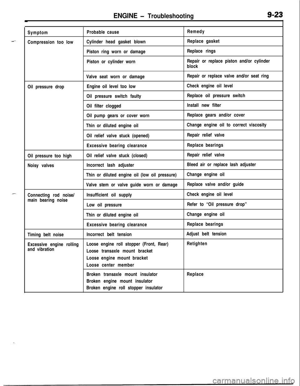
ENGINE - Troubleshooting9-23
--Symptom
Compression too lowProbable cause
Cylinder head gasket blown
Piston ring worn or damage
Piston or cylinder wornRemedy
Replace gasket
Replace rings
Repair or replace piston and/or cylinder
block
Valve seat worn or damageRepair or replace valve and/or seat ring
Oil pressure dropEngine oil level too lowCheck engine oil level
Oil pressure switch faultyReplace oil pressure switch
Oil filter cloggedInstall new filter
Oil pump gears or cover wornReplace gears and/or cover
Thin or diluted engine oilChange engine oil to correct viscosity
Oil relief valve stuck (opened)Repair relief valve
Excessive bearing clearanceReplace bearings
Oil pressure too highOil relief valve stuck (closed)Repair relief valve
Noisy valvesIncorrect lash adjusterBleed air or replace lash adjuster
Thin or diluted engine oil (low oil pressure)Change engine oil
Valve stem or valve guide worn or damageReplace valve and/or guide
Connecting rod noise/Insufficient oil supplyCheck engine oil level
main bearing noise
Low oil pressureRefer to “Oil pressure drop”
Thin or diluted engine oilChange engine oil
Excessive bearing clearanceReplace bearings
Timing belt noiseIncorrect belt tensionAdjust belt tension
Excessive engine rollingLoose engine roll stopper (Front, Rear)Retighten
and vibration
Loose transaxle mount bracket
Loose engine mount bracket
Loose center member
Broken transaxle mount insulatorReplace
Broken engine mount insulator
Broken engine roll stopper insulator