lock MITSUBISHI ECLIPSE 1991 Manual PDF
[x] Cancel search | Manufacturer: MITSUBISHI, Model Year: 1991, Model line: ECLIPSE, Model: MITSUBISHI ECLIPSE 1991Pages: 1216, PDF Size: 67.42 MB
Page 179 of 1216
![MITSUBISHI ECLIPSE 1991 Manual PDF BRAKES - Anti-lock Braking System Troubleshooting5-39
E-6Abnormality of valve relay drive circuitI
j-a [Explanation]When the ignition switch is turned ON, the ABSnormal. In addition, normally it monit MITSUBISHI ECLIPSE 1991 Manual PDF BRAKES - Anti-lock Braking System Troubleshooting5-39
E-6Abnormality of valve relay drive circuitI
j-a [Explanation]When the ignition switch is turned ON, the ABSnormal. In addition, normally it monit](/img/19/57104/w960_57104-178.png)
BRAKES - Anti-lock Braking System Troubleshooting5-39
E-6Abnormality of valve relay drive circuitI
j-a [Explanation]When the ignition switch is turned ON, the ABSnormal. In addition, normally it monitors whether or
ECU switches the valve relay OFF and ON for annot there is power in the valve power monitor line
initial check, compares the voltage of the signal tosince the valve relay is normally ON. Then, if the
the valve relay and valve power monitor line voltagesupply of power to the valve power monitor line is
to check whether the valve relay operation is
interrupted, the warning light illuminates.
IGNITIONMAIN FUSIBLESWITCHLINK @W-31)When the valve relay is
checked, are the followingconditions found?No.85-No.86:resistancevalue 60-120 Q
No.30-No.87a: continuityNo.30-No.87: No continui-
When battery voltage is ap-plied between terminals
No.86 and No. 85 grounded.
No. 30-No. 87: continuity
No.
30-No. 87a: no continui-
tyremove the HU connec-
NoValve relay malfunction
Replace valve relay.
IConnect the HU
remove the ECU con-
I Yes
IValve relay drive circuit isnormal.I
Page 180 of 1216
![MITSUBISHI ECLIPSE 1991 Manual PDF 5-40BRAKES - Anti-lock Braking System Troubleshooting
E-7Abnormality of motor drive circuit
[Explanation]The ABS ECU illuminates the warning light for the
motor relay and motor in the following cases. MITSUBISHI ECLIPSE 1991 Manual PDF 5-40BRAKES - Anti-lock Braking System Troubleshooting
E-7Abnormality of motor drive circuit
[Explanation]The ABS ECU illuminates the warning light for the
motor relay and motor in the following cases.](/img/19/57104/w960_57104-179.png)
5-40BRAKES - Anti-lock Braking System Troubleshooting
E-7Abnormality of motor drive circuit
[Explanation]The ABS ECU illuminates the warning light for the
motor relay and motor in the following cases.
l When the motor relay does not function
lWhen there is trouble with the motor itself and it
does not revolve
[Hint]If there is motor operation noise when wheel speed
exceeds
Gkm/h (4mph) when starting up after the
engine is started, there is a broken or short circuitedmotor monitor wire.
lWhen the motor ground line is disconnected andthe motor does not revolve
l When the motor continues to revolve
Does the motor make a
YesBroken wire or short cir-noise when wheel speed
-cuit in motor monitor line
exceeds 6 km/h (4 mph)?
b
NoRepair the harness between HU and ECU.
emove the motor rela
ABS ECU
14A0105
Remove the motor relav and
check resistance values.
No.
85-No. 86:resistancevalue 30-60 QNo.30-No.87: no continui-
ty
Battery voltage is applied on
terminals No. 86 and No. 85
grounded
No. 30-No. 87: continuity
Yes
q Motor relay malfunction 1
Replace motor relay.I
Is pump motor ground con-netted normally?Connect ground wire.I
b
Does voltage between bodyNo
connector terminal 51 andIBroken wire in pumpmotor power circuit
ground indicate battery vol-
tage?1Repair the harness.
YesIs resistance between body
- No L Malfunction of harness
connector terminal No. 2 andbetween HU and ECU
No.26 30-60 ohms?b
YesRepair harness.
Motor drive circuit is normal.
Page 181 of 1216
BRAKES - Service Adjustment Procedures5-47switch
switch
v14F516
Idown ,./
F14517
F14518
F14519
SERVICE ADJUSTMENT PROCEDURES
BRAKE PEDAL INSPECTION AND ADJUSTM&g
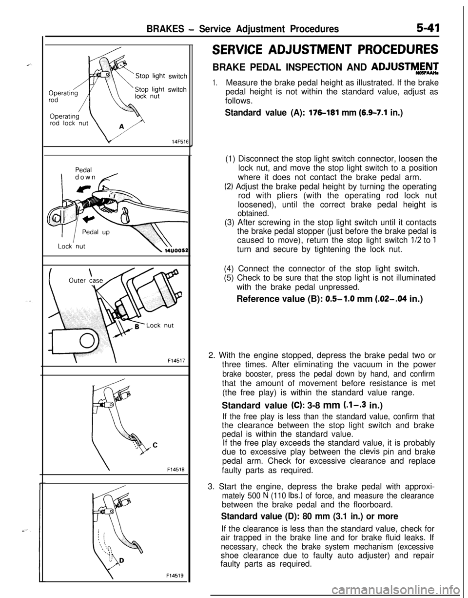
1.Measure the brake pedal height as illustrated. If the brake
pedal height is not within the standard value, adjust as
follows.
Standard value (A): 176181 mm (6.9-7.1 in.)(1) Disconnect the stop light switch connector, loosen the
lock nut, and move the stop light switch to a position
where it does not contact the brake pedal arm.
(2) Adjust the brake pedal height by turning the operating
rod with pliers (with the operating rod lock nut
loosened), until the correct brake pedal height is
obtained.(3) After screwing in the stop light switch until it contacts
the brake pedal stopper (just before the brake pedal is
caused to move), return the stop light switch
l/2 to 1turn and secure by tightening the lock nut.
(4) Connect the connector of the stop light switch.
(5) Check to be sure that the stop light is not illuminated
with the brake pedal unpressed.
Reference value (B): 0.5-1.0 mm
(.02-M in.)
2. With the engine stopped, depress the brake pedal two or
three times. After eliminating the vacuum in the power
brake booster, press the pedal down by hand, and confirmthat the amount of movement before resistance is met
(the free play) is within the standard value range.
Standard value
(C): 3-8 mm (.l-.3 in.)
If the free play is less than the standard value, confirm thatthe clearance between the stop light switch and brake
pedal is within the standard value.
If the free play exceeds the standard value, it is probably
due to excessive play between the
clevis pin and brake
pedal arm. Check for excessive clearance and replace
faulty parts as required.
3. Start the engine, depress the brake pedal with approxi-
mately 500 N (110 Ibs.) of force, and measure the clearancebetween the brake pedal and the floorboard.
Standard value (D): 80 mm (3.1 in.) or moreIf the clearance is less than the standard value, check for
air trapped in the brake line and for brake fluid leaks. If
necessary, check the brake system mechanism (excessiveshoe clearance due to faulty auto adjuster) and repair
faulty parts as required.
Page 185 of 1216
BRAKES - Service Adiustment Procedures5-45I
\\14A0416
2314A04.54
BLEEDINGN65FYAN
When the master cylinder is empty of brake fluid, bleed air
from the master cylinder by proceeding with procedures (1)
thru (6). (Because this master cylinder is not equipped with a
check valve.)
When brake fluid remains in the master cylinder, proceed with
step (6).
(1) -Disconnect the brake tube from the master cylinder.
(2) Two persons should conduct the air bleeding, one person
slowly depressing the brake pedal and holding the pedal
depressed.(3) In this condition, the other person should use a finger to
close the outlet part of the master cylinder, and then the
first person should release the brake pedal.
(4) Steps (2) and (3) should be repeated three or four times,
and then the master cylinder should be filled with brake
fluid to the specified level.
NOTE
The air is completely bled from the master cylinder by steps
(1) to (4).
(5) Connect the brake tube to the master cylinder.
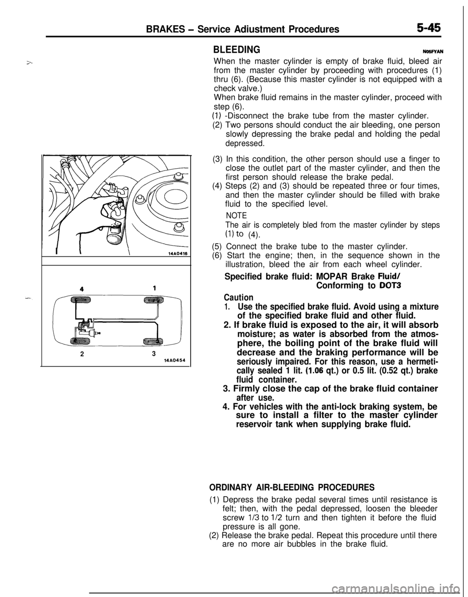
(6) Start the engine; then, in the sequence shown in the
illustration, bleed the air from each wheel cylinder.
Specified brake fluid: MOPAR Brake Fluid/
Conforming to DOT3
Caution
1.Use the specified brake fluid. Avoid using a mixture
of the specified brake fluid and other fluid.2. If brake fluid is exposed to the air, it will absorb
moisture; as water is absorbed from the atmos-phere, the boiling point of the brake fluid will
decrease and the braking performance will be
seriously impaired. For this reason, use a hermeti-
cally sealed 1 lit.
(1.06 qt.) or 0.5 lit. (0.52 qt.) brake
fluid container.3. Firmly close the cap of the brake fluid container
after use.
4. For vehicles with the anti-lock braking system, besure to install a filter to the master cylinder
reservoir tank when supplying brake fluid.
ORDINARY AIR-BLEEDING PROCEDURES(1) Depress the brake pedal several times until resistance is
felt; then, with the pedal depressed, loosen the bleeder
screw
l/3 to l/2 turn and then tighten it before the fluid
pressure is all gone.
(2) Release the brake pedal. Repeat this procedure until there
are no more air bubbles in the brake fluid.
Page 186 of 1216
5-46BRAKES - Service Adjustment ProceduresWhen new
When worn
14G0017
14LO169
14A0403
\14AO400
FRONT DISC BRAKE PAD CHECK AND REPLACE-
MENiNWFOAF
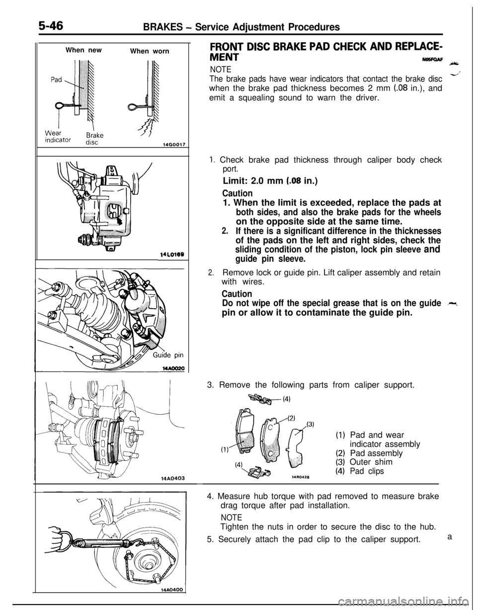
NOTE
The brake pads have wear indicators that contact the brake discd’when the brake pad thickness becomes 2 mm
(.08 in.), and
emit a squealing sound to warn the driver.
1. Check brake pad thickness through caliper body check
port.Limit: 2.0 mm
(.08 in.)
Caution1. When the limit is exceeded, replace the pads at
both sides, and also the brake pads for the wheelson the opposite side at the same time.
2.If there is a significant difference in the thicknesses
of the pads on the left and right sides, check the
sliding condition of the piston, lock pin sleeve and
guide pin sleeve.
2.Remove lock or guide pin. Lift caliper assembly and retain
with wires.
Caution
Do not wipe off the special grease that is on the guide
-pin or allow it to contaminate the guide pin.
3. Remove the following parts from caliper support.
=Qg@-(4)
(1)
(2)
(3)
(4)Pad and wear
indicator assembly
Pad assembly
Outer shimPad clips
-4. Measure hub torque with pad removed to measure brake
drag torque after pad installation.
NOTETighten the nuts in order to secure the disc to the hub.
5. Securely attach the pad clip to the caliper support.a
Page 187 of 1216
BRAKES - Service Adjustment Procedures5-47
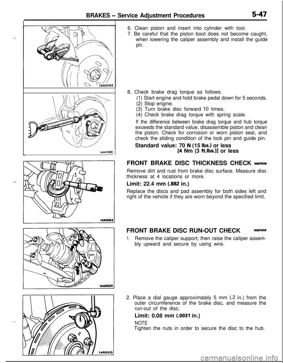
14AO399-6. Clean piston and insert into cylinder with tool.
7. Be careful that the piston boot does not become caught,
when lowering the caliper assembly and install the guide
pin.8. Check brake drag torque as follows.
(1) Start engine and hold brake pedal down for 5 seconds.
(2) Stop engine.
(3) Turn brake disc forward
10 times.
(4) Check brake drag torque with spring scale.
If the difference between brake drag torque and hub torqueexceeds the standard value, disassemble piston and clean
the piston. Check for corrosion or worn piston seal, and
check the sliding condition of the lock pin and guide pin.
Standard value: 70
N (15 Ibs.) or less
[4 Nm (3 ftlbs.)] or less
FRONT BRAKE DISC THICKNESS CHECK
NQ5FRASRemove dirt and rust from brake disc surface. Measure disc
thickness at 4 locations or more.
Limit: 22.4 mm
(.882 in.)
Replace the discs and pad assembly for both sides left and
right of the vehicle if they are worn beyond the specified limit.
FRONT BRAKE DISC RUN-OUT CHECKNOIFSAB
1.Remove the caliper support; then raise the caliper assem-
bly upward and secure by using wire.
2. Place a dial gauge approximately 5 mm
(2 in.) from the
outer circumference of the brake disc, and measure the
run-out of the disc.
Limit: 0.08 mm
(.0031 in.)
NOTETighten the nuts in order to secure the disc to the hub.
Page 188 of 1216
5-48BRAKES - Service Adjustment Procedures
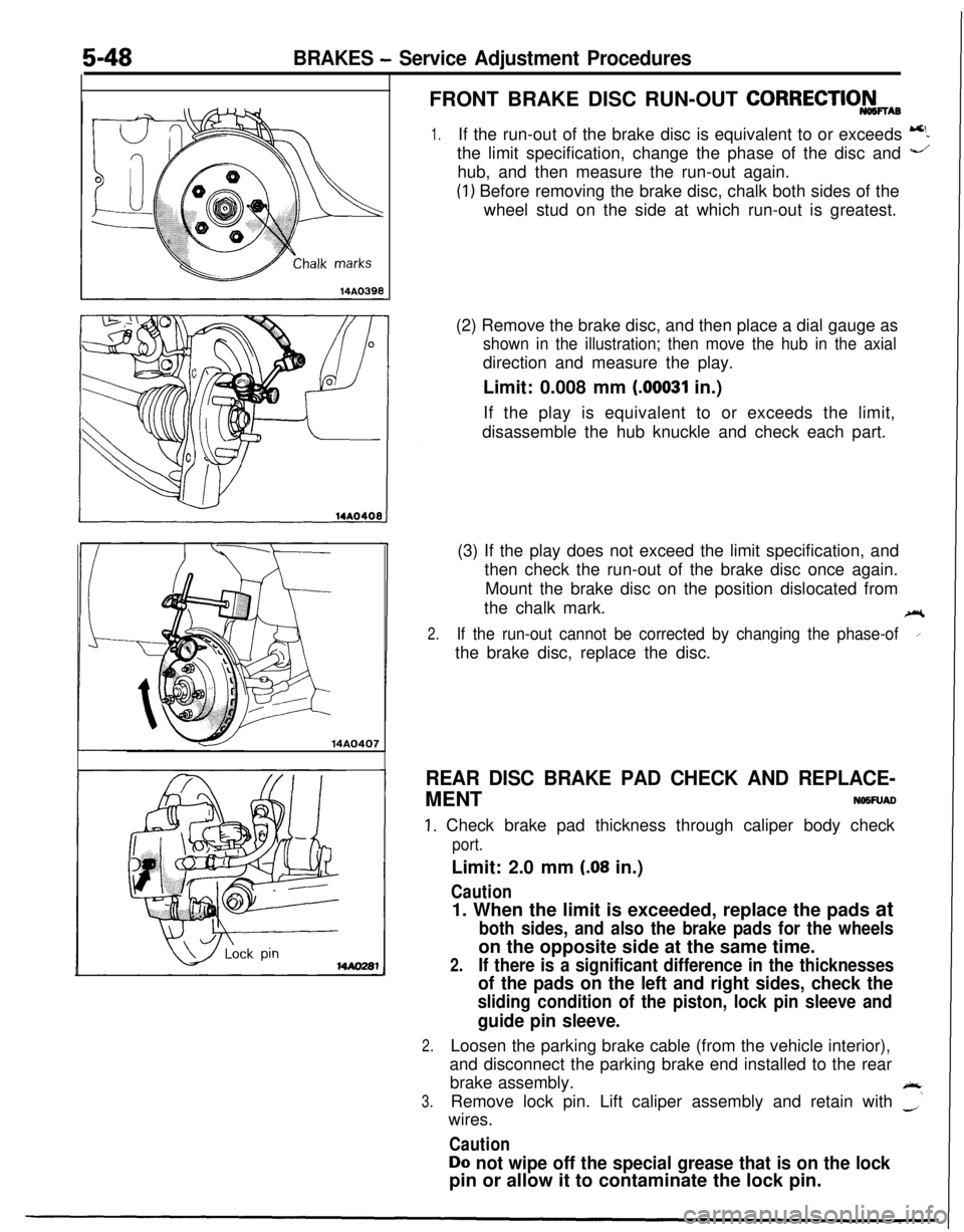
14A0407FRONT BRAKE DISC RUN-OUT
CORRECTIO&wAB
1.If the run-out of the brake disc is equivalent to or exceeds 5the limit specification, change the phase of the disc and
-’hub, and then measure the run-out again.
(1) Before removing the brake disc, chalk both sides of the
wheel stud on the side at which run-out is greatest.
(2) Remove the brake disc, and then place a dial gauge as
shown in the illustration; then move the hub in the axialdirection and measure the play.
Limit: 0.008 mm
(00031 in.)
If the play is equivalent to or exceeds the limit,
disassemble the hub knuckle and check each part.
(3) If the play does not exceed the limit specification, and
then check the run-out of the brake disc once again.
Mount the brake disc on the position dislocated from
the chalk mark.
ei
2.If the run-out cannot be corrected by changing the phase-ofI’the brake disc, replace the disc.
REAR DISC BRAKE PAD CHECK AND REPLACE-MENT
NO5FUAD
1. Check brake pad thickness through caliper body check
port.Limit: 2.0 mm
(.08 in.)
Caution1. When the limit is exceeded, replace the pads at
both sides, and also the brake pads for the wheelson the opposite side at the same time.
2.If there is a significant difference in the thicknesses
of the pads on the left and right sides, check the
sliding condition of the piston, lock pin sleeve and
guide pin sleeve.
2.Loosen the parking brake cable (from the vehicle interior),
and disconnect the parking brake end installed to the rear
brake assembly.
A
3.Remove lock pin. Lift caliper assembly and retain with -‘wires.
Caution
Do not wipe off the special grease that is on the lockpin or allow it to contaminate the lock pin.
Page 189 of 1216
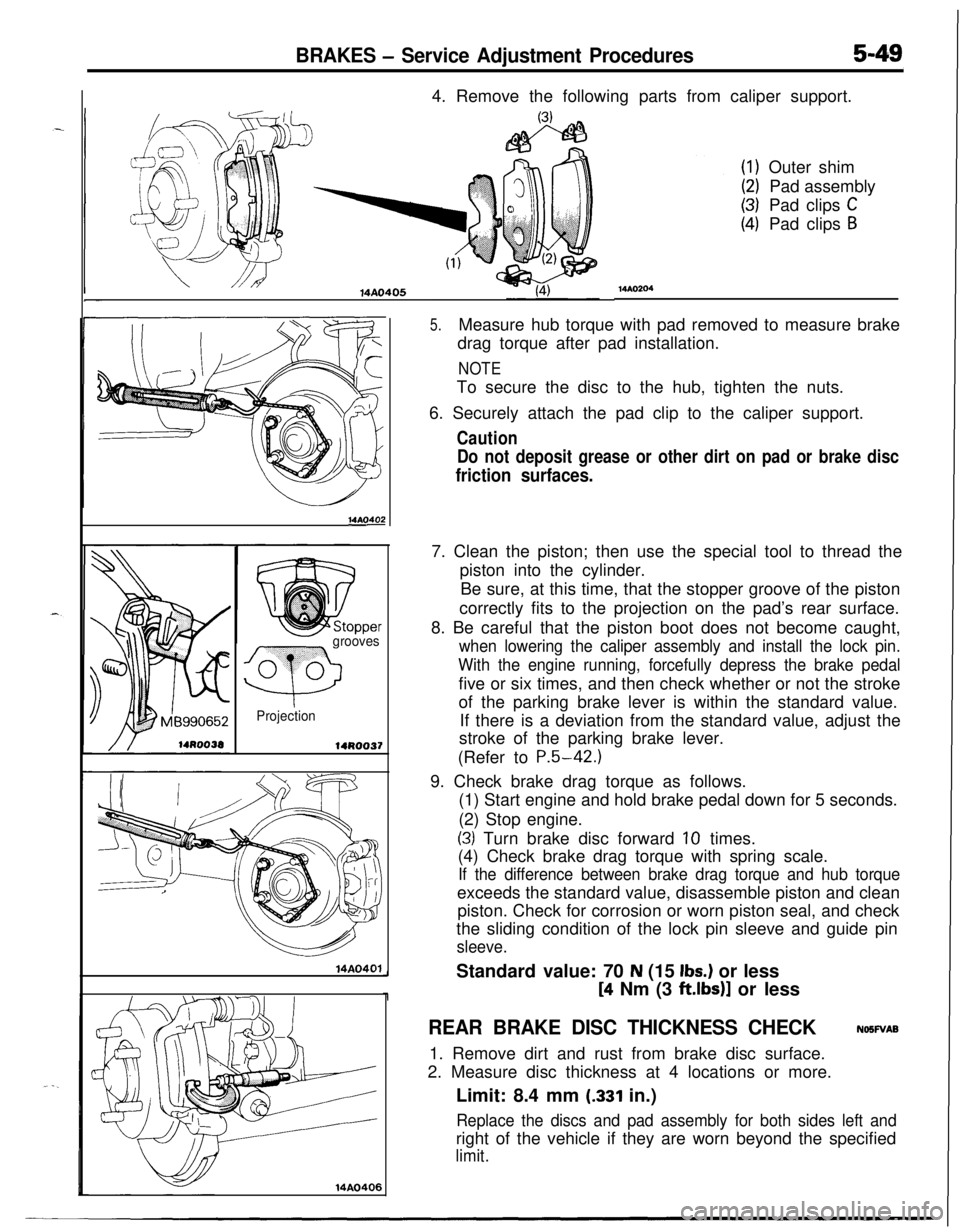
BRAKES - Service Adjustment Procedures5-494. Remove the following parts from caliper support.
14AO405
14AOs
grooves
Q
0 0
Projection
14R0037
14A0401
14AO406
MAO204Outer shim
Pad assembly
Pad clips
CPad clips
B
5.Measure hub torque with pad removed to measure brake
drag torque after pad installation.
NOTETo secure the disc to the hub, tighten the nuts.
6. Securely attach the pad clip to the caliper support.
Caution
Do not deposit grease or other dirt on pad or brake disc
friction surfaces.7. Clean the piston; then use the special tool to thread the
piston into the cylinder.
Be sure, at this time, that the stopper groove of the piston
correctly fits to the projection on the pad’s rear surface.
8. Be careful that the piston boot does not become caught,
when lowering the caliper assembly and install the lock pin.
With the engine running, forcefully depress the brake pedalfive or six times, and then check whether or not the stroke
of the parking brake lever is within the standard value.
If there is a deviation from the standard value, adjust the
stroke of the parking brake lever.
(Refer to
P.5-42.)9. Check brake drag torque as follows.
(1) Start engine and hold brake pedal down for 5 seconds.
(2) Stop engine.
(3) Turn brake disc forward 10 times.
(4) Check brake drag torque with spring scale.
If the difference between brake drag torque and hub torqueexceeds the standard value, disassemble piston and clean
piston. Check for corrosion or worn piston seal, and check
the sliding condition of the lock pin sleeve and guide pin
sleeve.Standard value: 70
N (15 Ibs.) or less
[4 Nm (3 ft.lbs)] or less
REAR BRAKE DISC THICKNESS CHECKNOSWAB
1. Remove dirt and rust from brake disc surface.
2. Measure disc thickness at 4 locations or more.
Limit: 8.4 mm
(.331 in.)
Replace the discs and pad assembly for both sides left andright of the vehicle if they are worn beyond the specified
limit.
Page 193 of 1216
BRAKES - Brake Pedal5-53
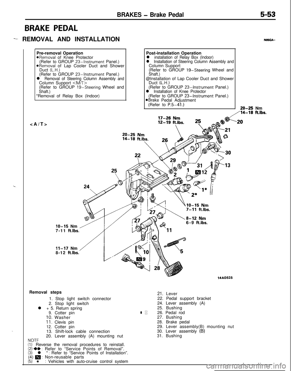
BRAKE PEDAL
-I REMOVAL AND INSTALLATION
.Pre-removal Operation
aRemoval of Knee Protector
(Refer to GROUP 23%Instrument Panel.)
ORemoval of Lap Cooler Duct and Shower
Duct (L.H.)(Refer to GROUP 23-Instrument Panel.)l Removal of Steering Column Assembly andColumn Support
(Refer to GROUP
19-Steering Wheel andShaft.)*Removal of Relay Box (Indoor)
NO5OA--Post-installation Operation
l installation of Relay Box (Indoor)l Installation of Steering Column Assembly andColumn Support
(Refer to GROUP 19-Steering Wheel and
Shaft.)@Installation of Lap Cooler Duct and Shower
Duct
(L.H.)(Refer to GROUP 23-Instrument Panel.)l Installation of Knee Protector(Refer to GROUP 23-Instrument Panel.)aBrake Pedal Adjustment
(Refer to P.5-41.)20-25 Nm
,‘14-18 ft.lbs.
IO-15 Nm /7-11 ft.lbs.
/
11-17 Nm
8-12 ftlbs.6-9
ftlbs.Removal steps
1. Stop light switch connector
2. Stop light switch
l + 5. Return spring
9.Cotter pin10.Washer11.Clevis pin12.Cotter pin
13. Shift-lock cable connection
20. Lever assembly (A) mounting nut
NOTF(i, Reverse the removal procedures to reinstall.(2) 4I) : Refer to “Service Points of Removal”.(3) l * : Refer to “Service Points of Installation”.
(4) m : Non-reusable parts
(5) *: Vehicles with auto-cruise control system
14A0525
l *
21.Lever
22. Pedal support bracket
24. Lever assembly (A)
25.Bushing
26. Pedal rod
27.Bushing
28.Brake pedal
29. Lever assembly(B) mounting nut
30. Lever assembly
(B)31.Bushing
.20
Page 194 of 1216
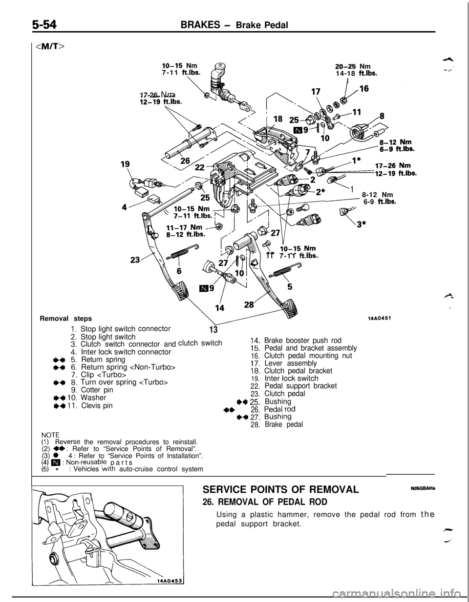
5-54BRAKES -Brake Pedal
IO-15 Nm
7-11 ft.lbs.
\
20-25 Nm
14-18 ft.lbs.I17-26 Nm
12-19 ft.lbs.
18-12 Nm
- 6-9 ft.lbs.- /-
117-11 ft.lbs.
13clutch switch Stop light switchconnectorStop light switch
Clutch switch connector andInter lock switch connector
Return springReturn spring
Clip
Turn over spring
Cotter pin
Washer
Clevis pin
1::16.
1::19.
22.
23.
W 25.
4*26.I)4 27.28.
Brake booster push rod
Pedal and bracket assembly
Clutch pedal mounting nut
Lever assembly
Clutch pedal bracketInter lock switch
Pedal support bracket
Clutch pedal
Bushing
P,;$;d
Brake pedal
14AG451
Fyfeverse the removal procedures to reinstall.
(2) 4* : Refer to “Service Points of Removal”.
(3) l 4 : Refer to “Service Points of Installation”.# m : Non-reusabje parts*: Vehicles with auto-cruise control system
SERVICE POINTS OF REMOVAL
NO5GBAHa
26. REMOVAL OF PEDAL RODUsing a plastic hammer, remove the pedal rod from the
pedal support bracket.