engine MITSUBISHI ECLIPSE 1991 Service Manual
[x] Cancel search | Manufacturer: MITSUBISHI, Model Year: 1991, Model line: ECLIPSE, Model: MITSUBISHI ECLIPSE 1991Pages: 1216, PDF Size: 67.42 MB
Page 308 of 1216
9-24ENGINE - Service Adjustment Procedures
ENGINE 4.8L Engine>
SERVICE ADJUSTMENT PROCEDURES -
CHECKING COMPRESSION PRESSURENOSFFAI
(1) Before checking compression, ensure that engine oil, the
starter motor, and battery are all in good condition.
(2) Start the engine and wait until engine coolant temperature
has risen to
85-95°C (185-205°F).
(3) Stop the engine and pull the spark plug cables.
(4) Remove the spark plugs.
(5) Crank the engine to remove any foreign objects in the
cylinders.Caution
Cover the spark plug holes with shop towel, etc., in
order to keep expelled foreign objects from flying out,
and keep away from the holes. When measuring
compression with water, oil, or fuel having entered the
cylinder through a crack, etc., these will come flying
out of the spark plug hole hot and fast, so be sure to
take the proper precautions.
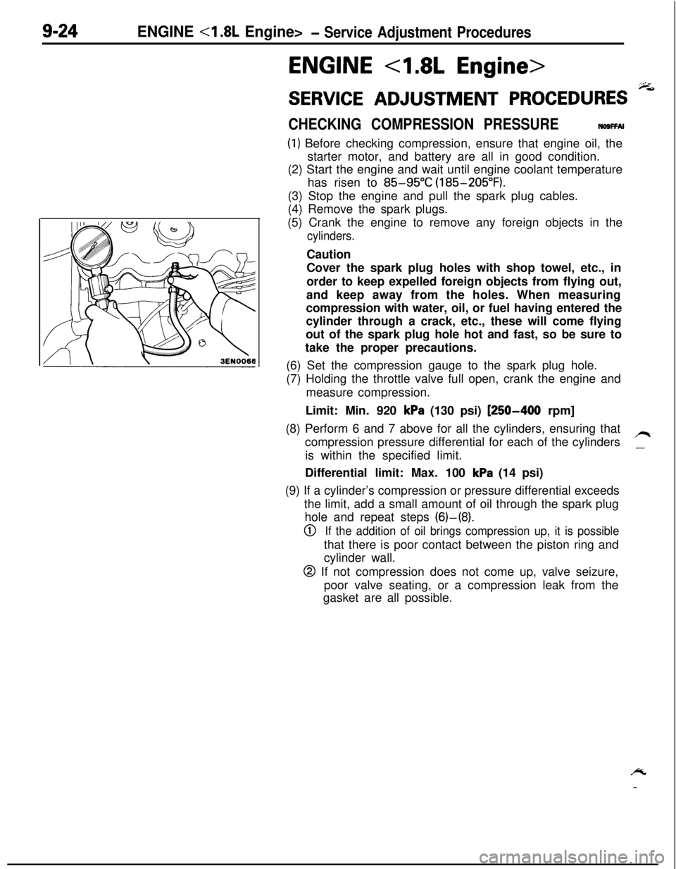
(6) Set the compression gauge to the spark plug hole.
(7) Holding the throttle valve full open, crank the engine and
measure compression.
Limit: Min. 920
kPa (130 psi) [250-400 rpm]
(8) Perform 6 and 7 above for all the cylinders, ensuring that
compression pressure differential for each of the cylinders
/Iis within the specified limit.
__Differential limit: Max. 100
kPa (14 psi)
(9) If a cylinder’s compression or pressure differential exceeds
the limit, add a small amount of oil through the spark plug
hole and repeat steps (6)-(8).
0If the addition of oil brings compression up, it is possiblethat there is poor contact between the piston ring and
cylinder wall.
@ If not compression does not come up, valve seizure,
poor valve seating, or a compression leak from the
gasket are all possible.
/y
-
Page 309 of 1216
ENGINE <1.8L Engine>- Service Adjustment Procedures9-25
MANIFOLD VACUUM INSPECTION(1) Before inspection and adjustment, put the vehicle
in=following state.
l Engine coolant temperature:
85-95°C (185-205°F)
l Lights, electric, cooling fan, and accessories: OFF
lTransaxle: Neutral
(N or P for vehicles with an automa-
tic transaxle)
l Steering wheel: Neutral position
(2) Check that the idling revolution speed is normal.
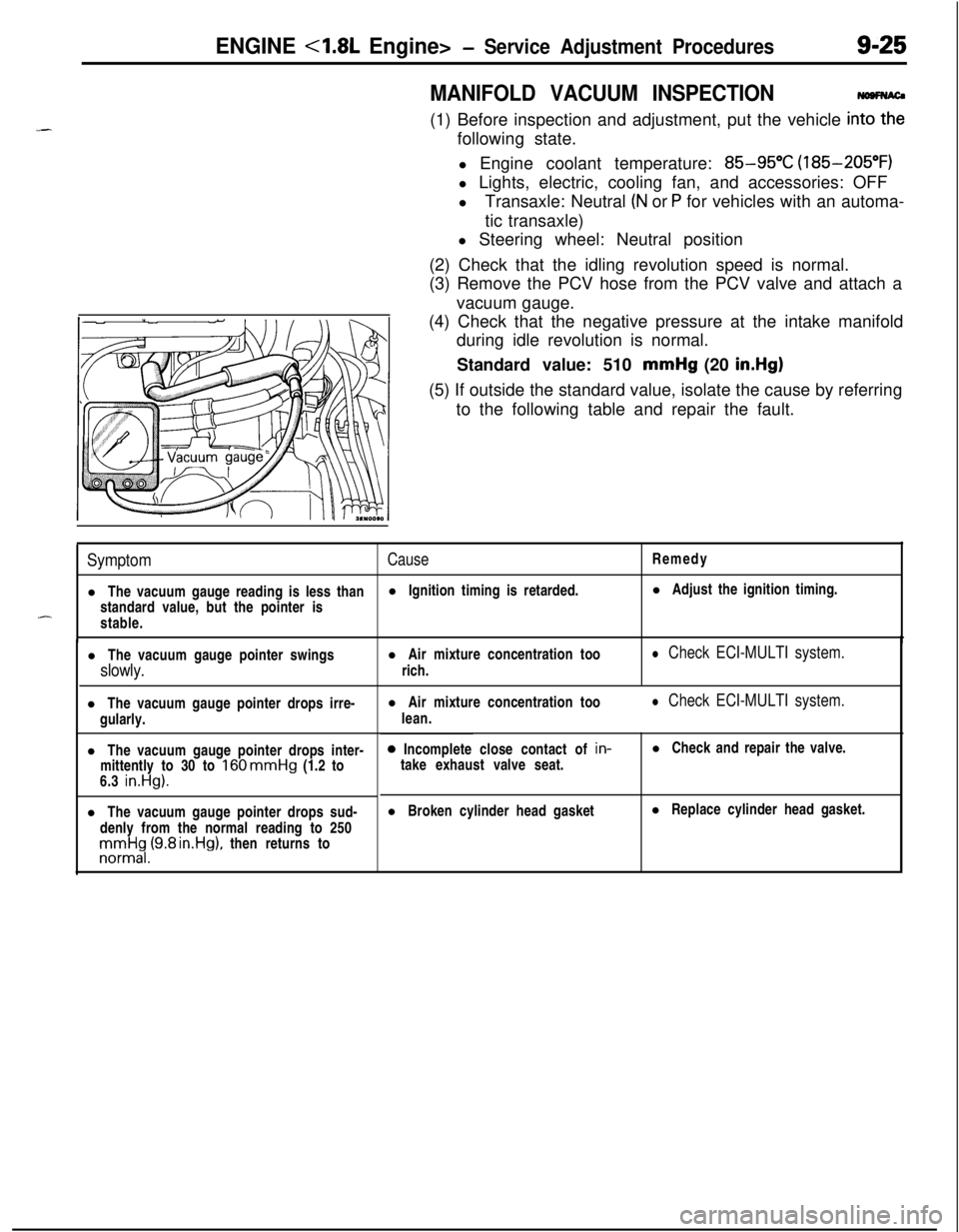
(3) Remove the PCV hose from the PCV valve and attach a
vacuum gauge.
(4) Check that the negative pressure at the intake manifold
during idle revolution is normal.
Standard value: 510 mmHg (20
in.Hg)(5) If outside the standard value, isolate the cause by referring
to the following table and repair the fault.
SymptomCauseRemedy
l The vacuum gauge reading is less thanl Ignition timing is retarded.l Adjust the ignition timing.
standard value, but the pointer is
-stable.
l The vacuum gauge pointer swingsl Air mixture concentration too
slowly.rich.
l Check ECI-MULTI system.l The vacuum gauge pointer drops irre-
gularly.
l The vacuum gauge pointer drops inter-
mittently to 30 to
160 mmHg (1.2 to
6.3 in.Hg).l The vacuum gauge pointer drops sud-
denly from the normal reading to 250rronnrt$,(9.8 rn.Hg), then returns tol Air mixture concentration too
lean.
l Check ECI-MULTI system.0 Incomplete close contact of in-
take exhaust valve seat.l Check and repair the valve.
l Broken cylinder head gasketl Replace cylinder head gasket.
Page 310 of 1216
9-26ENGINE <1.8L Engine> -Service Adjustment Procedures
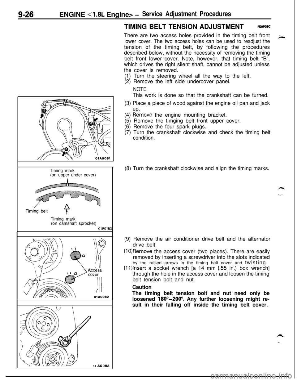
TIMING BELT TENSION ADJUSTMENTNOSFGBCThere are two access holes provided in the timing belt front
lower cover. The two access holes can be used to readjust thetension of the timing belt, by following the procedures
described below, without the necessity of removing the timing
belt front lower cover. Note, however, that timing belt “B”,
which drives the right silent shaft, cannot be adjusted unless
the cover is removed.
(1) Turn the steering wheel all the way to the left.
(2) Remove the left side undercover panel.
NOTEThis work is done so that the crankshaft can be turned.
(3) Place a piece of wood against the engine oil pan and jack
(4)
:tmove the engine mounting bracket.
(5) Remove the timging belt front upper cover.
(6) Remove the four spark plugs.
(7) Turn the crankshaft clockwise and check the timing belt
condition.
OlAOOBlTiming mark
(on upper under cover)
Timing mark
(on camshaft sprocket)
OlR0153cover
‘I!i
OlA0082
01 A0083(8) Turn the crankshaft clockwise and align the timing marks.
(9) Remove the air conditioner drive belt and the alternator
drive belt.
(10)Remove the access cover (two places). There are easily
removed by inserting a screwdriver into the slots indicated
by the raised arrows in the timing belt cover and twisting.
(1l)lnser-t a socket wrench [a 14 mm (.55 in.) box wrench]
through the hole in the access cover and loosen the timing
belt tension bolt and nut.
Caution
The timing belt tension bolt and nut need only be
loosened
180”-200”. Any further loosening might re-
sult in their falling off inside the timing belt cover.
Page 311 of 1216
ENGINE <1.8L Engine> -Service Adjustment Procedures9-27
I.
Timing mark(on upper under cover)Timing belt
Timing mark
A(on camshaft
sprocket)OlR0154
3EN076
3EN07;-
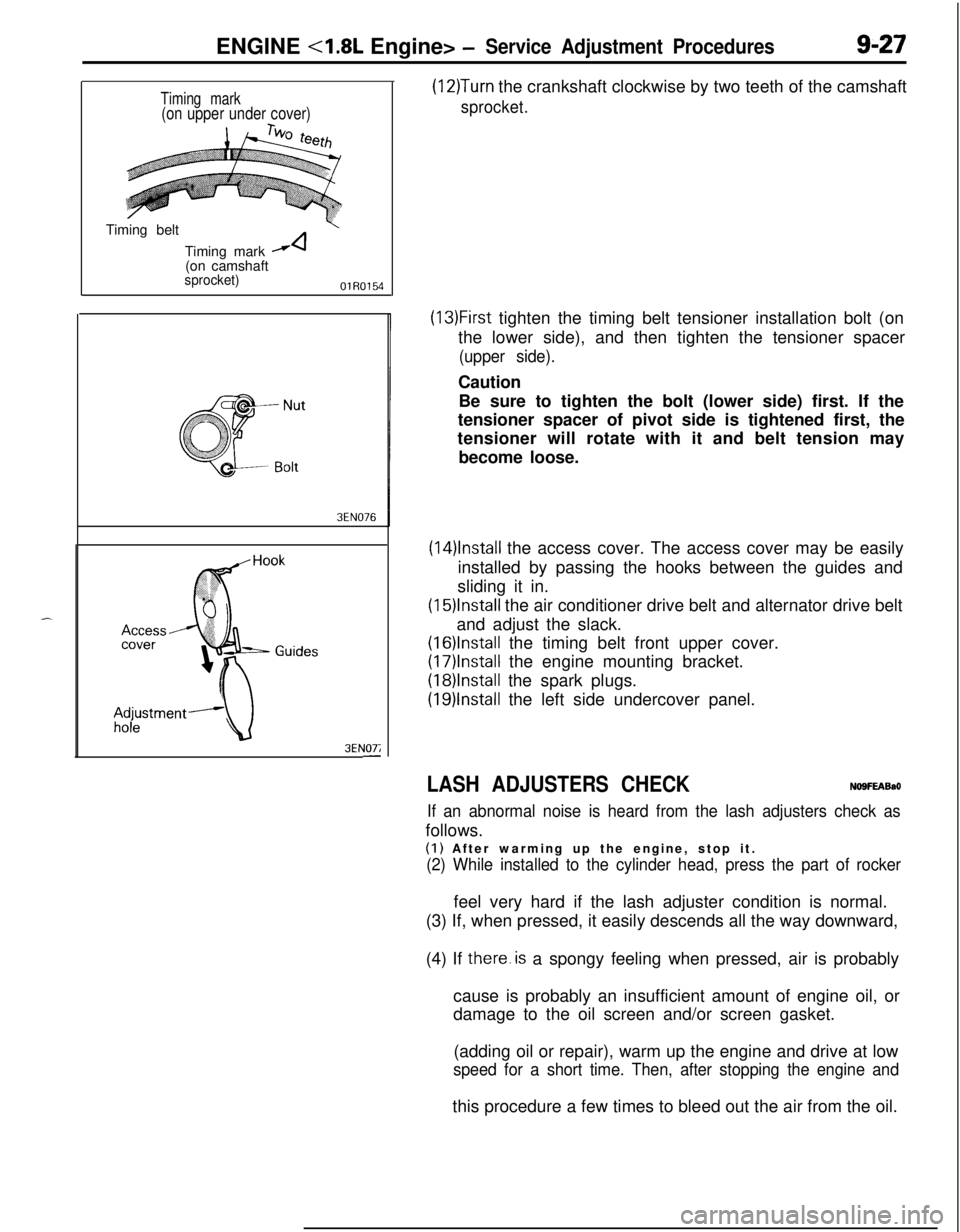
(12)Turn the crankshaft clockwise by two teeth of the camshaft
sprocket.
(13)First tighten the timing belt tensioner installation bolt (on
the lower side), and then tighten the tensioner spacer
(upper side).Caution
Be sure to tighten the bolt (lower side) first. If the
tensioner spacer of pivot side is tightened first, the
tensioner will rotate with it and belt tension may
become loose.
(14)lnstall the access cover. The access cover may be easily
installed by passing the hooks between the guides and
sliding it in.
(15)lnstall the air conditioner drive belt and alternator drive belt
and adjust the slack.
(16)lnstalI the timing belt front upper cover.
(17)lnstall the engine mounting bracket.
(18)lnstalI the spark plugs.
(19)lnstall the left side undercover panel.
LASH ADJUSTERS CHECKNO9FEABaO
If an abnormal noise is heard from the lash adjusters check asfollows.
(I) After warming up the engine, stop it.
(2) While installed to the cylinder head, press the part of rockerfeel very hard if the lash adjuster condition is normal.
(3) If, when pressed, it easily descends all the way downward,
(4) If there.is a spongy feeling when pressed, air is probably
cause is probably an insufficient amount of engine oil, or
damage to the oil screen and/or screen gasket.
(adding oil or repair), warm up the engine and drive at low
speed for a short time. Then, after stopping the engine andthis procedure a few times to bleed out the air from the oil.
Page 312 of 1216
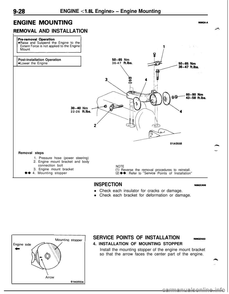
9-28ENGINE <1.8L Engine> - Engine Mounting
ENGINE MOUNTING
IEMOVAL AND INSTALLATION
NOB8A-APost-installation Operation
50-65 Nm*Lower the Engine36-47 ft.lbs.
30-40 Nm
22-26 ft.lbs.Removal steps
1. Pressure hose (power steering)
2. Engine mount bracket and body
connection bolt
3. Engine mount bracket
e+ 4. Mounting stopper
NOTE(1) Reverse the removal procedures to reinstall.(2) +* : Refer to “Service Points of Installation”
INSPECTIONNOOQCANOl Check each insulator for cracks or damage.
l Check each bracket for deformation or damage.
MountingSERVICE POINTS OF INSTALLATION4. INSTALLATION OF MOUNTING STOPPER
Install the mounting stopper of the engine mount bracket
so that the arrow faces the center part of the engine.
Arrow
OiA0004
Page 313 of 1216
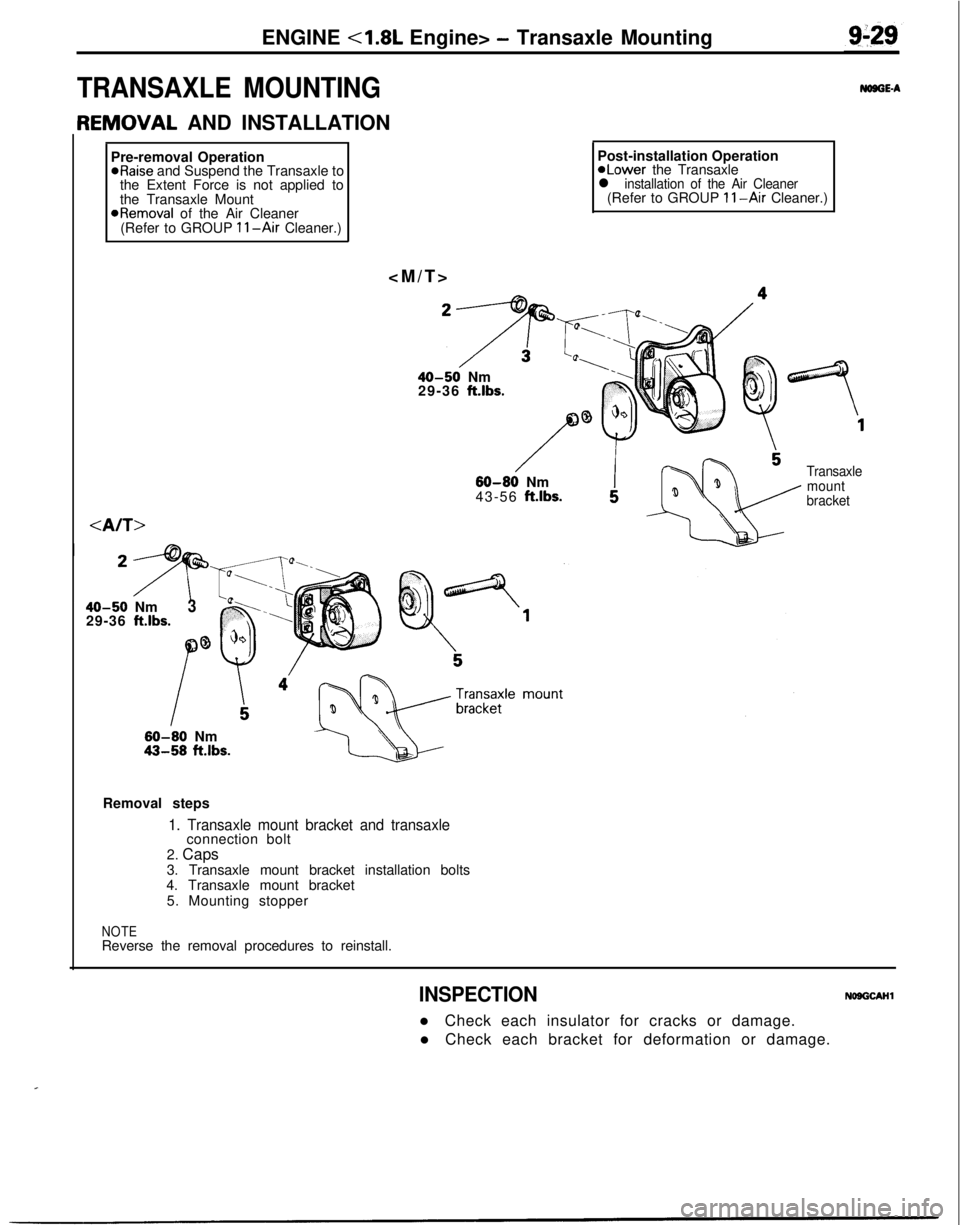
ENGINE <1.8L Engine> - Transaxle Mounting
TRANSAXLE MOUNTING
IEMOVAL AND INSTALLATION
Pre-removal Operation*Raise and Suspend the Transaxle to
the Extent Force is not applied to
the Transaxle Mount
@Removal of the Air Cleaner
(Refer to GROUP 11-Air Cleaner.)
NOSGE-APost-installation OperationaLower the Transaxle
l installation of the Air Cleaner(Refer to GROUP II-Air Cleaner.)
40-50 Nm
29-36 ft.lbs.
/W-60 Nm
43-56 ft.lbs.
Transaxle
mount
bracket
40-50 Nm
29-36 ft.lbs.3
60-80 Nm43-58 ft.lbs.Removal steps
1. Transaxle mount bracket and transaxleconnection bolt
2. Caps
3. Transaxle mount bracket installation bolts
4. Transaxle mount bracket
5. Mounting stopper
NOTEReverse the removal procedures to reinstall.
INSPECTIONNOOGCAHll Check each insulator for cracks or damage.
l Check each bracket for deformation or damage.
.I
Page 314 of 1216
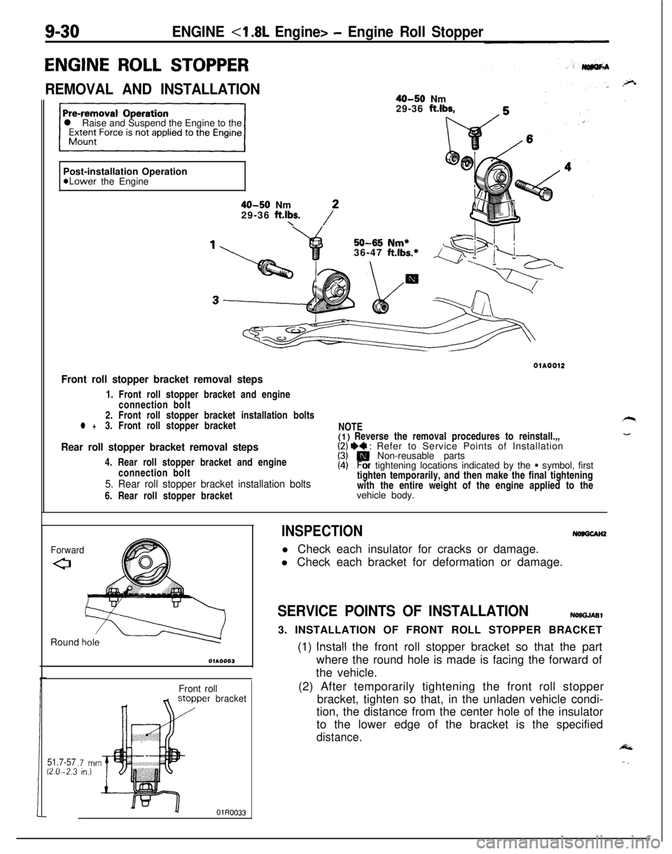
50-65 Nm*36-47 ft.lbs.*
9-30ENGINE - Engine Roll Stopper
ENGINE ROLL STOPPER
REMOVAL AND INSTALLATION40-50 Nm
29-36 ft.lbs.
l Raise and Suspend the Engine to the
Post-installation Operation
*Lower the Engine
40-50 Nm
29-36 ft.lbs.\/*01A0012
Front roll stopper bracket removal steps1. Front roll stopper bracket and engine
connection bolt
2. Front roll stopper bracket installation bolts
l +3. Front roll stopper bracket
Rear roll stopper bracket removal steps4. Rear roll stopper bracket and engine
connection bolt
5. Rear roll stopper bracket installation bolts6. Rear roll stopper bracketNOTE
(1) Reverse the removal procedures to reinstall.,,
I;/ I)+ : Refer to Service Points of Installation
Non-reusable parts
(4)Por tightening locations indicated by the * symbol, first
tighten temporarily, and then make the final tightening
with the entire weight of the engine applied to the
vehicle body.
ForwardRound
h&Front roll
51.7-5712.0-2.3.7 mnin.)
bracket
INSPECTIONNosGcAH2l Check each insulator for cracks or damage.
l Check each bracket for deformation or damage.
SERVICE POINTS OF INSTALLATIONNOSGJASl3. INSTALLATION OF FRONT ROLL STOPPER BRACKET
(1)
Install the front roll stopper bracket so that the part
where the round hole is made is facing the forward of
the vehicle.
(2) After temporarily tightening the front roll stopper
bracket, tighten so that, in the unladen vehicle condi-
tion, the distance from the center hole of the insulator
to the lower edge of the bracket is the specified
distance.
Page 315 of 1216
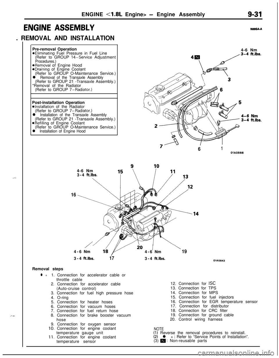
ENGINE <1.8L Engine> - Engine Assembly9-31
ENGINE ASSEMBLY
. REMOVAL AND INSTALLATION
N69SA-APre-removal Operation
@Eliminating Fuel Pressure in Fuel Line
(Refer to GROUP 14-Service AdjustmentProcedures.)@Removal of Engine HoodeDraining of Engine Coolant
(Refer to GROUP O-Maintenance Service.)
l Removal of the Transaxle Assembly(Refer to GROUP 21 -Transaxle Assembly.)
*Removal of the Radiator
(Refer to GROUP 7-Radiator.)
Post-installation Operation
@Installation of the Radiator
(Refer to GROUP 7-Radiator.)
l Installation of the Transaxle Assembly(Refer to GROUP 21 -Transaxle Assembly.)
@Refilling of Engine Coolant
(Refer to GROUP O-Maintenance Service.)
l Installation of Engine Hood4-6 Nm
“7
/61OlA05664-6 Nm
3-4
ft.lbs.
\
16
/io1\4-6Nm164-6Nm193-4ft.lbs.
173-4ft.lbs.OlA0643Removal steps
l +1. Connection for accelerator cable or
throttle cable
2. Connection for accelerator cable
(Auto-cruise control)
3. Connection for fuel high pressure hose
4. O-ring
5. Connection for heater hoses
6. Connection for vacuum hoses
7. Connection for fuel return hose
8. Connection for brake booster vacuum
hose
9. Connection for oxygen sensor
10. Connection for engine coolant
temperature gauge unit
11. Connection for engine coolant
temperature sensor12. Connection for
ISC13. Connection for TPS
14. Connection for MPS
15. Connection for fuel injectors
16. Connection for EGR temperature sensor
17. Connection for distributor
18. Connection for CRC filter
19. Connection for ground cable
20. Control wiring harness
NOTE(1) Reverse the removal procedures to reinstall.(2) l + : Refer to “Service Points of Installation”.
(3) m : Non-reusable parts
Page 316 of 1216
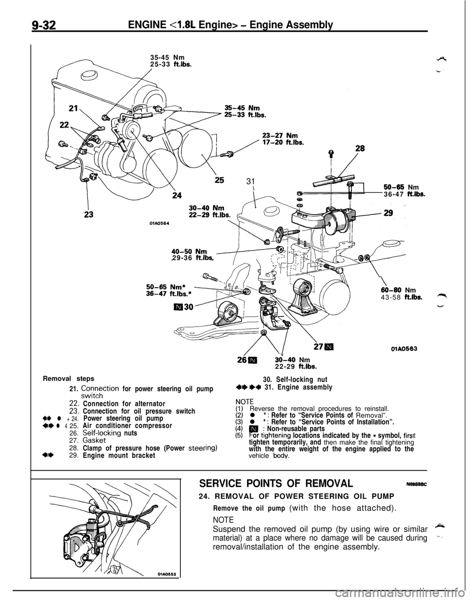
9-32ENGINE <1.8L Engine> - Engine Assembly35-45 Nm
25-33
ft.lbs.
25 31\5$M35 Nm
36-47 ft.lbs.
OlAO56429-36
ft.lbs.
3&40 Nm
22-29 ft.lbs.
Removal steps
21.
zztTtion for power steering oil pump30. Self-locking nut4e +4 31. Engine assembly
+e l + 24.*I)l 425.
26.27.
28.
4+29.
\60-80 Nm
43-58 ft.lbs.
OlAO563Connection for alternator
Connection for oil pressure switch
Power steering oil pump
Air conditioner compressor
palffz,cklng nuts
Clamp of pressure hose (Power
steelEngine mount bracket
ITEReverse the removal procedures to reinstall.
l *
: Refer to “Service Points of Removal”.
l * : Refer to “Service Points of Installation”.
P; Non-reusable parts
or ttghtening locations indicated by the * symbol, firs1tighten temporarily, and then make the final tightening
with the entire weight of the engine applied to the
vehicle
body.
t
SERVICE POINTS OF REMOVALNogs6SC24. REMOVAL OF POWER STEERING OIL PUMP
Remove the oil pump (with the hose attached).
NOTESuspend the removed oil pump (by using wire or similar
material) at a place where no damage will be caused duringremoval/installation of the engine assembly.
Page 317 of 1216
ENGINE <1.8L Engine> - Engine Assemblv9-33
c
!
OlAO582
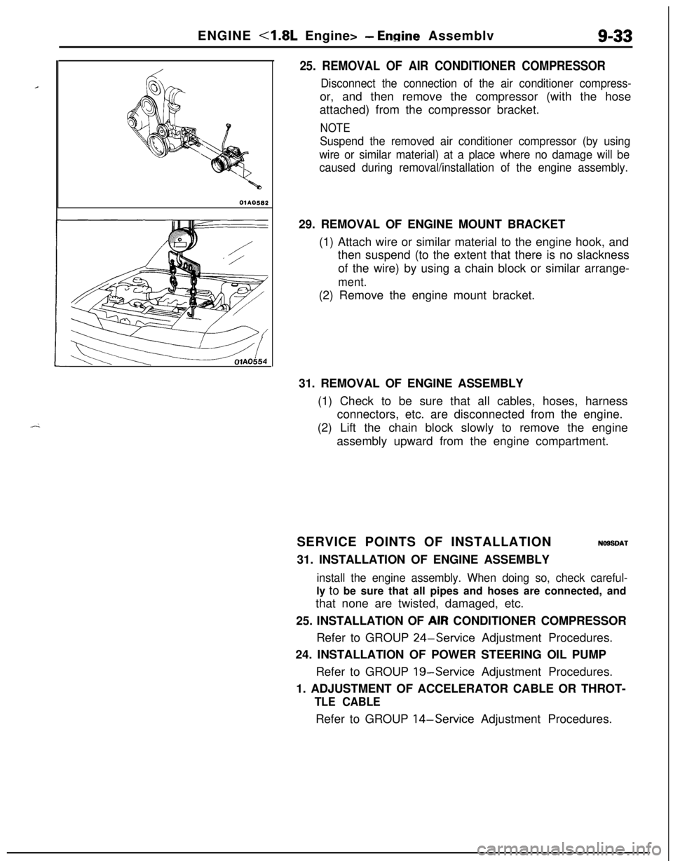
25. REMOVAL OF AIR CONDITIONER COMPRESSOR
Disconnect the connection of the air conditioner compress-or, and then remove the compressor (with the hose
attached) from the compressor bracket.
NOTE
Suspend the removed air conditioner compressor (by using
wire or similar material) at a place where no damage will be
caused during removal/installation of the engine assembly.29. REMOVAL OF ENGINE MOUNT BRACKET
(1) Attach wire or similar material to the engine hook, and
then suspend (to the extent that there is no slackness
of the wire) by using a chain block or similar arrange-
ment.(2) Remove the engine mount bracket.
31. REMOVAL OF ENGINE ASSEMBLY
(1) Check to be sure that all cables, hoses, harness
connectors, etc. are disconnected from the engine.
(2) Lift the chain block slowly to remove the engine
assembly upward from the engine compartment.
SERVICE POINTS OF INSTALLATION
NOSSDAT31. INSTALLATION OF ENGINE ASSEMBLY
install the engine assembly. When doing so, check careful-ly to be sure that all pipes and hoses are connected, and
that none are twisted, damaged, etc.
25. INSTALLATION OF AIR CONDITIONER COMPRESSOR
Refer to GROUP
24-Service Adjustment Procedures.
24. INSTALLATION OF POWER STEERING OIL PUMP
Refer to GROUP
19-Service Adjustment Procedures.
1. ADJUSTMENT OF ACCELERATOR CABLE OR THROT-
TLE CABLERefer to GROUP
14-Service Adjustment Procedures.