MITSUBISHI LANCER 2005 Workshop Manual
Manufacturer: MITSUBISHI, Model Year: 2005, Model line: LANCER, Model: MITSUBISHI LANCER 2005Pages: 788, PDF Size: 45.98 MB
Page 351 of 788
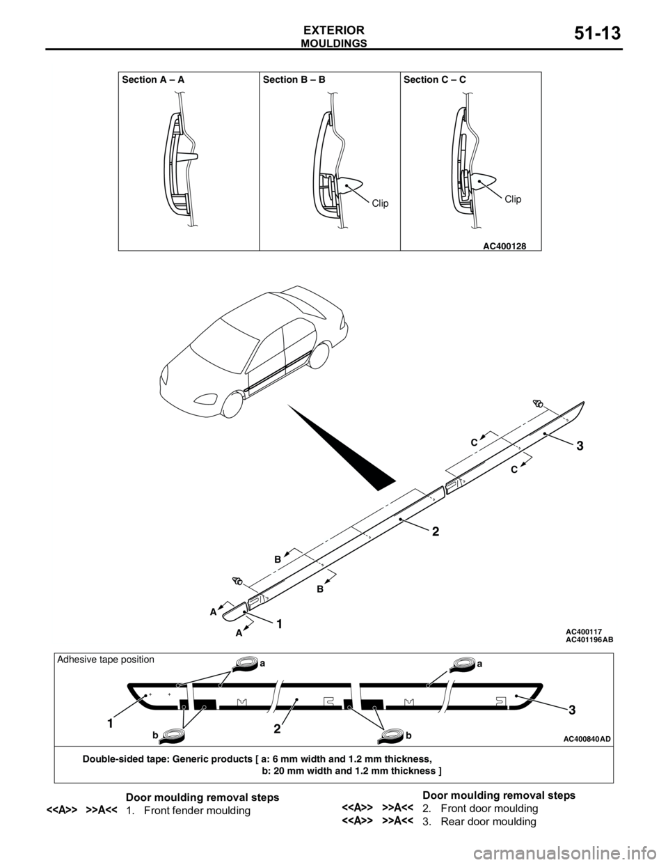
MOULDINGS
EXTERIOR51-13
AC401196 AC400117
AC400128
Section A – A Section B – B Section C – C
AB
A
AB
BC
C
2
1
3
ClipClip
AC400840AD
Double-sided tape: Generic products [ a: 6 mm width and 1.2 mm thickness,
b: 20 mm width and 1.2 mm thickness ]
12
3
a
b baAdhesive tape position
Door moulding removal steps
<> >>A<<1. Front fender mouldingDoor moulding removal steps<> >>A<<2. Front door moulding
<> >>A<<3. Rear door moulding
Page 352 of 788
Page 353 of 788
SIDE AIR DAM
EXTERIOR51-15
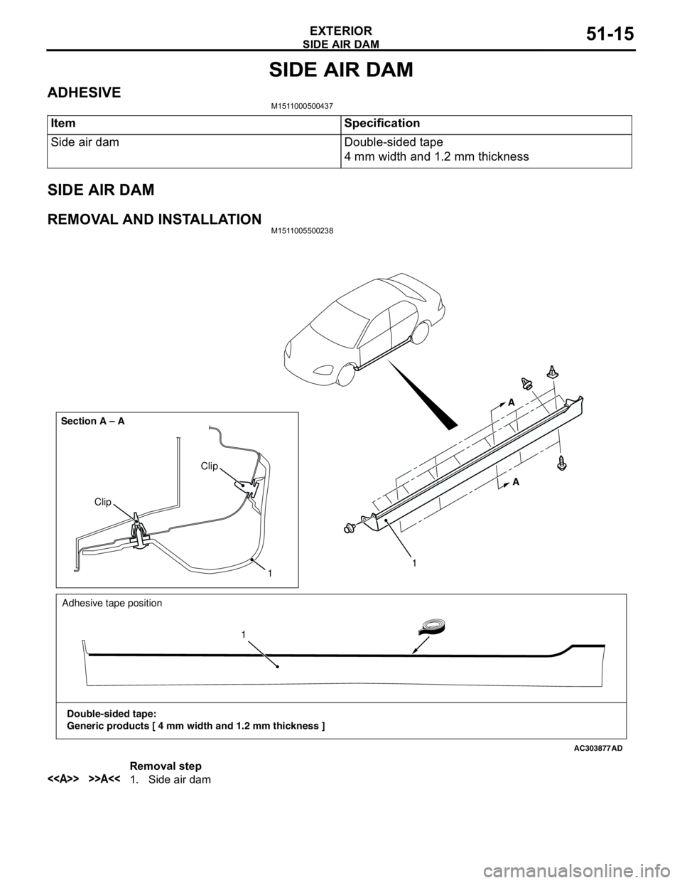
SIDE AIR DAM
ADHESIVEM1511000500437
SIDE AIR DAM
REMOVAL AND INSTALLATIONM1511005500238
Item Specification
Side air dam Double-sided tape
4 mm width and 1.2 mm thickness
AC303877
Clip
Clip Section A – A
AD
1
A A
Adhesive tape position
Double-sided tape:
Generic products [ 4 mm width and 1.2 mm thickness ]11
Removal step
<> >>A<<1. Side air dam
Page 354 of 788
Page 355 of 788
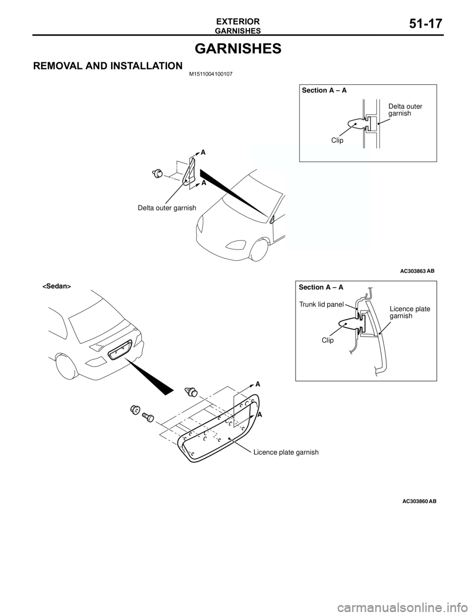
GARNISHES
EXTERIOR51-17
GARNISHES
REMOVAL AND INSTALLATIONM1511004100107
AC303863
Clip
Delta outer garnishSection A – A
AB
Delta outer
garnish
A A
AC303860
A A
Clip Trunk lid panel
Licence plate
garnish Section A – A
AB
Licence plate garnish
Page 356 of 788
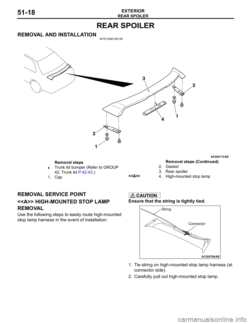
REAR SPOILER
EXTERIOR51-18
REAR SPOILER
REMOVAL AND INSTALLATIONM1511006100136
REMOVAL SERVICE POINT
<> HIGH-MOUNTED STOP LAMP
REMOVAL
Use the following steps to easily route high-mounted
stop lamp harness in the event of installation:
CAUTION
Ensure that the string is tightly tied.
1. Tie string on high-mounted stop lamp harness (at
connector side).
2. Carefully pull out high-mounted stop lamp.
AC303713
2 3
4
2
1
AB
1
Removal steps
•Trunk lid bumper (Refer to GROUP
42, Trunk lid P.42-43.)
1. Cap2. Gasket
3. Rear spoiler
<>4. High-mounted stop lampRemoval steps (Continued)
AC303708
Connector String
AB
Page 357 of 788
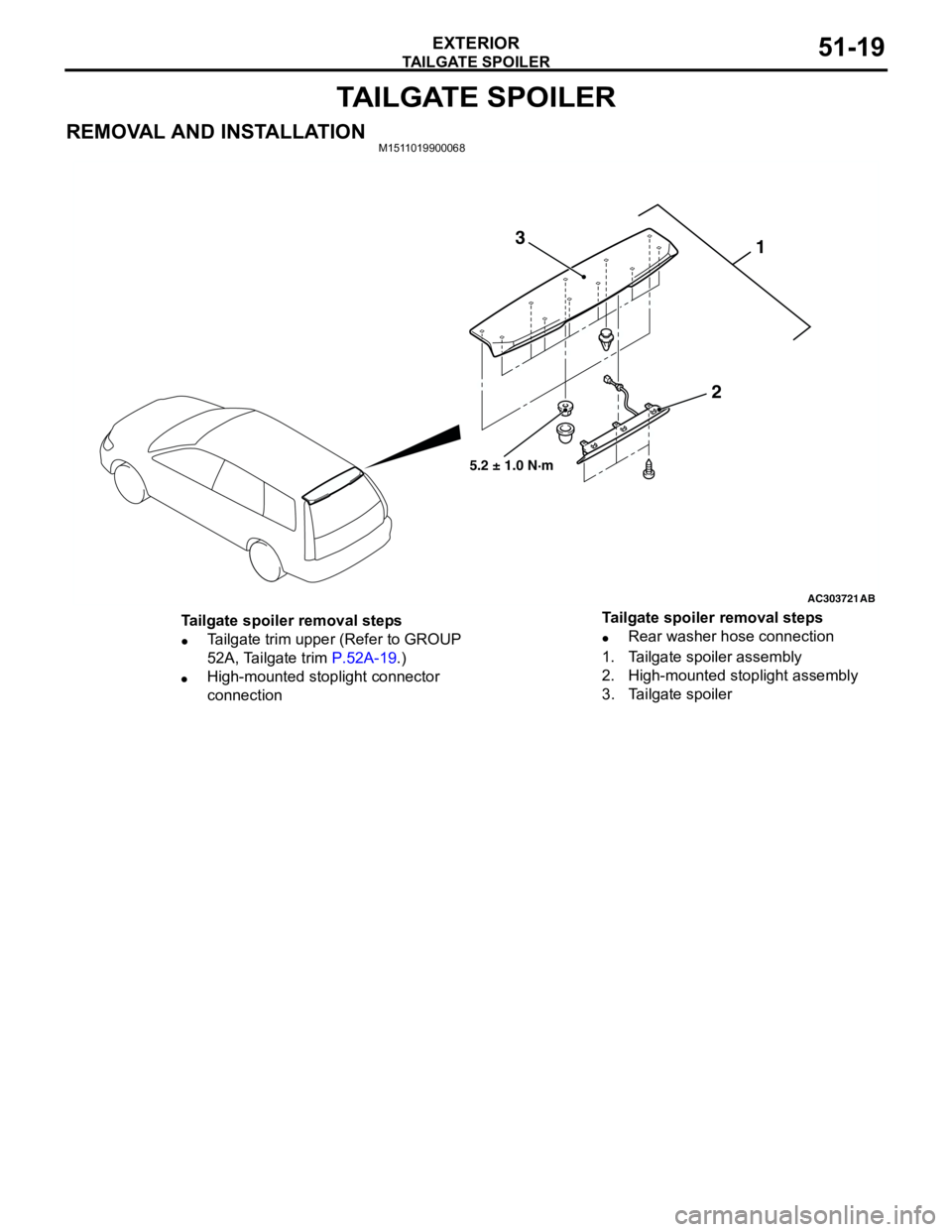
TAILGATE SPOILER
EXTERIOR51-19
TAILGATE SPOILER
REMOVAL AND INSTALLATIONM1511019900068
AC303721
1
2 3
AB
5.2 ± 1.0 N·m
Tailgate spoiler removal steps
•Tailgate trim upper (Refer to GROUP
52A, Tailgate trim P.52A-19.)
•High-mounted stoplight connector
connection•Rear washer hose connection
1. Tailgate spoiler assembly
2. High-mounted stoplight assembly
3. Tailgate spoiler Tailgate spoiler removal steps
Page 358 of 788
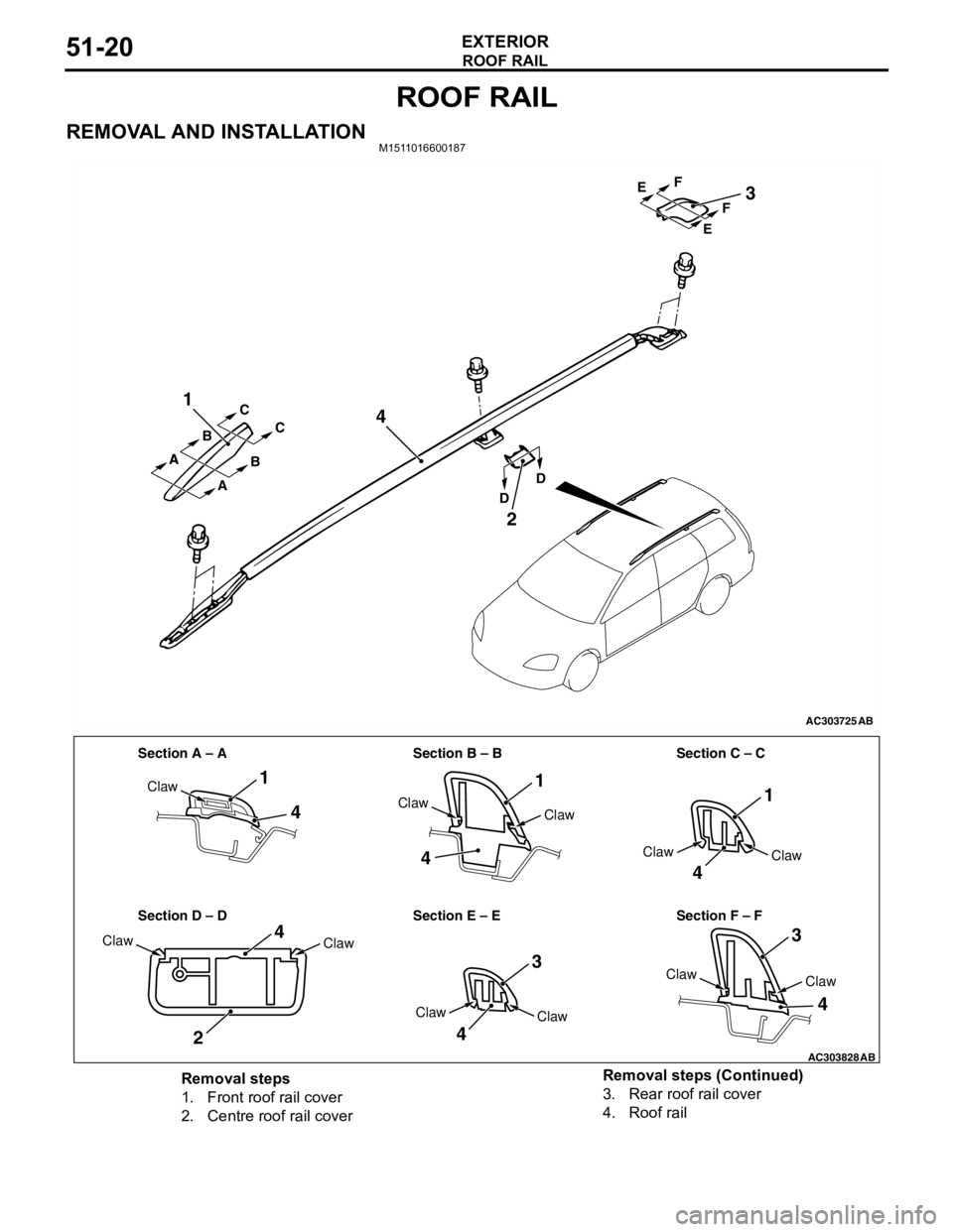
ROOF RAIL
EXTERIOR51-20
ROOF RAIL
REMOVAL AND INSTALLATIONM1511016600187
AC303725
1
4
2
3
AB
A A
A BC
C
B
DDEF EF
AC303828
Section A – A Section B – B Section C – C
Section D – D Section E – E Section F – F
1
4
4
11
4
3
3
4
4
2
4
Claw
Claw
Claw
Claw
Claw
Claw
ClawClaw
Claw
Claw
Claw
AB
Removal steps
1. Front roof rail cover
2. Centre roof rail cover3. Rear roof rail cover
4. Roof rail Removal steps (Continued)
Page 359 of 788

WINDSHIELD WIPER AND WASHER
EXTERIOR51-21
WINDSHIELD WIPER AND WASHER
GENERAL INFORMATIONM1511000100514
WINDSHIELD WIPER AND WASHER
OPERATION
Windshield Low-speed (and High-speed)
Wiper Operation
•If the windshield low-speed wiper switch is turned
to the ON position with the ignition switch at the
"ACC" or "ON" position, the column switch sends
a low-speed wiper ON and high-speed wiper OFF
signals to the front-ECU. This turns the wiper
signal on and the wiper speed control relay off
(low-speed), causing the wipers to operate at
low-speed.
•If the windshield high-speed wiper switch is
turned to the ON position, the column switch
sends a low-speed wiper OFF and high-speed
wiper ON signals to the front-ECU. This turns
both the wiper signal and the wiper speed control
relay on (high-speed), causing the wipers to
operate at high-speed.
NOTE: The windshield wiper speed is switchable
with the built-in wiper speed control relay.
High-speed operations take place when the wiper
speed control relay is set to "ON" and low-speed
operations take place when the wiper speed control
relay is set to "OFF".
Windshield Intermittent Wiper Operation
The ETACS-ECU calculates the wiper operation
interval according to the voltage signal sent from the
column switch. Then the ETACS-ECU sends a signal
to the front-ECU. The front-ECU determines the
wiper operation interval and turns on the wiper relay
signal relay. This causes the wiper auto stop relay to
turn on. Then the wiper auto stop relay will turn off
after the wipers reach the park position. This causes
the wiper signal relay and then the wipers to turn off.
If the wiper signal relay remains off for the wiper
operation interval, the relay turns on again, causing
the wipers to operate in intermittent mode.
Windshield Mist Wiper Operation
•If the windshield mist wiper switch is turned to the
ON position with the ignition switch at the "ACC"
or "ON" position, the mist wiper high-speed
operation signal is sent to the front-ECU. This
signal turns on the wiper speed control relay,
causing the wipers to work at high-speed while
the mist switch is on.
•While the windshield mist wiper switch remains
turned on when the intermittent mode is still
working, the wipers work as the mist wiper.
However, the wipers return to the intermittent
mode again when the switch is changed back to
"INT" position.
•To prevent the windshield mist wiper from
operating when the windshield wiper switch is
turned OFF, the windshield mist wiper does not
work for 0.5 second after the windshield
intermittent wiper switch, the windshield
low-speed wiper switch and the windshield
high-speed wiper switch are turned OFF.
Windshield Washer Operation
•If the windshield washer switch is turned to ON
position with the ignition switch at "ACC" or "ON"
position, the windshield washer ON signal is sent
to the front-ECU. After 0.3 second, the windshield
wiper signal turns on. After the windshield washer
switch signal turns off, the windshield wiper signal
turns off in three seconds.
•If the windshield washer switch is turned on while
the windshield wiper is at intermittent mode,
when the windshield washer switch is turned OFF
within 0.2 second, the wiper works only once to
perform mist operation by the windshield washer
switch. When the ON condition of the windshield
washer switch continues more than 0.2 second,
the wiper performs the same movement as
normal condition from the time when 0.2 second
has elapsed and then returns to the intermittent
motion.
Page 360 of 788
WINDSHIELD WIPER AND WASHER
EXTERIOR51-22
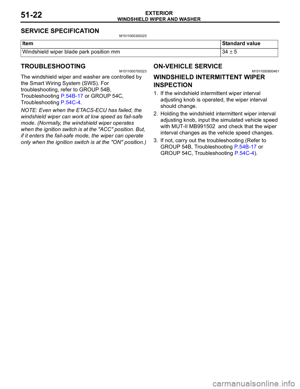
SERVICE SPECIFICATIONM1511000300325
TROUBLESHOOTINGM1511000700323
The windshield wiper and washer are controlled by
the Smart Wiring System (SWS). For
troubleshooting, refer to GROUP 54B,
Troubleshooting P.54B-17 or GROUP 54C,
Troubleshooting P.54C-4.
NOTE: Even when the ETACS-ECU has failed, the
windshield wiper can work at low speed as fail-safe
mode. (Normally, the windshield wiper operates
when the ignition switch is at the "ACC" position. But,
if it enters the fail-safe mode, the wiper can operate
only when the ignition switch is at the "ON" position.)
ON-VEHICLE SERVICEM1511000800461
WINDSHIELD INTERMITTENT WIPER
INSPECTION
1. If the windshield intermittent wiper interval
adjusting knob is operated, the wiper interval
should change.
2. Holding the windshield intermittent wiper interval
adjusting knob, input the simulated vehicle speed
with MUT-II MB991502 and check that the wiper
interval changes as the vehicle speed changes.
3. If not, carry out the troubleshooting (Refer to
GROUP 54B, Troubleshooting P.54B-17 or
GROUP 54C, Troubleshooting P.54C-4). ItemStandard value
Windshield wiper blade park position mm 34 ± 5