MITSUBISHI LANCER 2005 Workshop Manual
Manufacturer: MITSUBISHI, Model Year: 2005, Model line: LANCER, Model: MITSUBISHI LANCER 2005Pages: 788, PDF Size: 45.98 MB
Page 381 of 788
DOOR MIRROR
EXTERIOR51-43
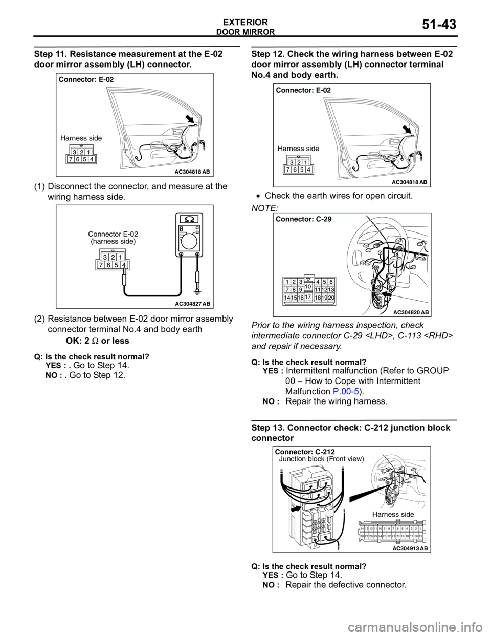
Step 11. Resistance measurement at the E-02
door mirror assembly (LH) connector.
(1) Disconnect the connector, and measure at the
wiring harness side.
(2) Resistance between E-02 door mirror assembly
connector terminal No.4 and body earth
OK: 2 Ω or less
Q: Is the check result normal?
YES : .
Go to Step 14.
NO : . Go to Step 12.
Step 12. Check the wiring harness between E-02
door mirror assembly (LH) connector terminal
No.4 and body earth.
•Check the earth wires for open circuit.
NOTE:
Prior to the wiring harness inspection, check
intermediate connector C-29
and repair if necessary.
Q: Is the check result normal?
YES :
Intermittent malfunction (Refer to GROUP
00 − How to Cope with Intermittent
Malfunction P.00-5).
NO : Repair the wiring harness.
Step 13. Connector check: C-212 junction block
connector
Q: Is the check result normal?
YES :
Go to Step 14.
NO : Repair the defective connector.
AC304818
Connector: E-02
Harness side
AB
AC304827
Connector E-02
(harness side)
AB
AC304818
Connector: E-02
Harness side
AB
AC304820
Connector: C-29
AB
AC304913
21716151718 201912345 623 222425282627981011141213
Connector: C-212
Harness side
AB
Junction block (Front view)
Page 382 of 788
DOOR MIRROR
EXTERIOR51-44
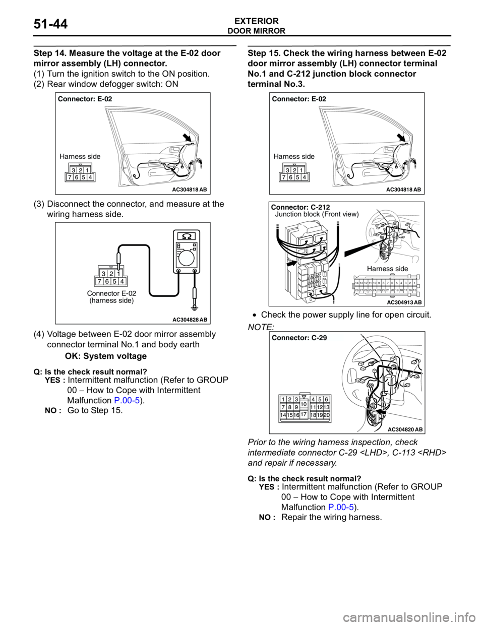
Step 14. Measure the voltage at the E-02 door
mirror assembly (LH) connector.
(1) Turn the ignition switch to the ON position.
(2) Rear window defogger switch: ON
(3) Disconnect the connector, and measure at the
wiring harness side.
(4) Voltage between E-02 door mirror assembly
connector terminal No.1 and body earth
OK: System voltage
Q: Is the check result normal?
YES :
Intermittent malfunction (Refer to GROUP
00 − How to Cope with Intermittent
Malfunction P.00-5).
NO : Go to Step 15.
Step 15. Check the wiring harness between E-02
door mirror assembly (LH) connector terminal
No.1 and C-212 junction block connector
terminal No.3.
•Check the power supply line for open circuit.
NOTE:
Prior to the wiring harness inspection, check
intermediate connector C-29
and repair if necessary.
Q: Is the check result normal?
YES :
Intermittent malfunction (Refer to GROUP
00 − How to Cope with Intermittent
Malfunction P.00-5).
NO : Repair the wiring harness.
AC304818
Connector: E-02
Harness side
AB
AC304828
Connector E-02
(harness side)
AB
AC304818
Connector: E-02
Harness side
AB
AC304913
21716151718 201912345 623 222425282627981011141213
Connector: C-212
Harness side
AB
Junction block (Front view)
AC304820
Connector: C-29
AB
Page 383 of 788
DOOR MIRROR
EXTERIOR51-45
DOOR MIRROR
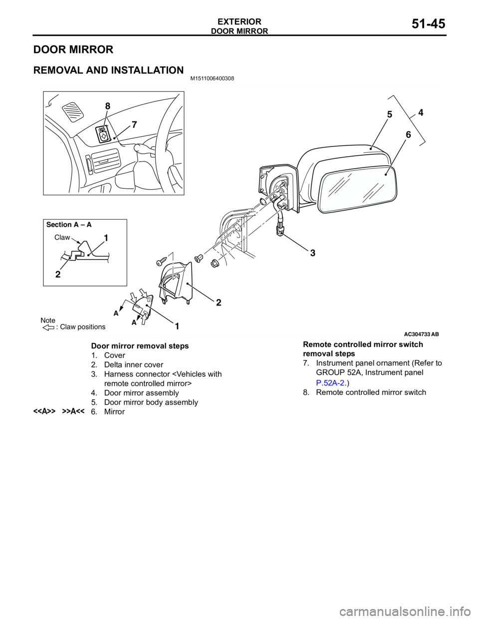
REMOVAL AND INSTALLATIONM1511006400308
AC304733
Note
: Claw positions
AB
A
A Section A – A
Claw1
2
1234
5
6 7 8
Door mirror removal steps
1. Cover
2. Delta inner cover
3. Harness connector
4. Door mirror assembly
5. Door mirror body assembly
<> >>A<<6. MirrorRemote controlled mirror switch
removal steps
7. Instrument panel ornament (Refer to
GROUP 52A, Instrument panel
P.52A-2.)
8. Remote controlled mirror switch
Page 384 of 788
Page 385 of 788
DOOR MIRROR
EXTERIOR51-47
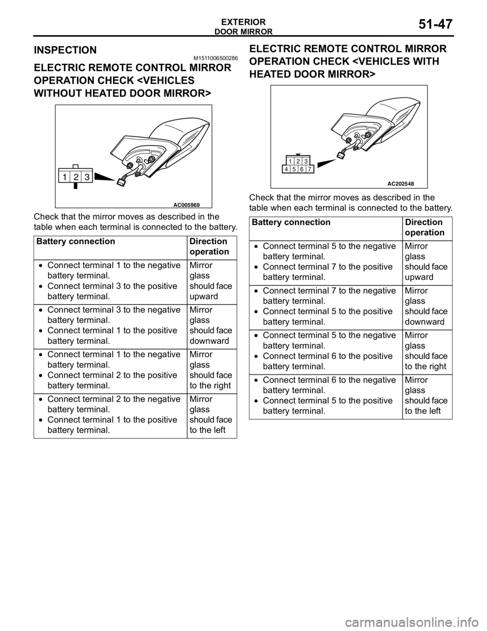
INSPECTIONM1511006500286
ELECTRIC REMOTE CONTROL MIRROR
OPERATION CHECK
Check that the mirror moves as described in the
table when each terminal is connected to the battery.
ELECTRIC REMOTE CONTROL MIRROR
OPERATION CHECK
Check that the mirror moves as described in the
table when each terminal is connected to the battery.
Battery connection Direction
operation
•Connect terminal 1 to the negative
battery terminal.
•Connect terminal 3 to the positive
battery terminal.Mirror
glass
should face
upward
•Connect terminal 3 to the negative
battery terminal.
•Connect terminal 1 to the positive
battery terminal.Mirror
glass
should face
downward
•Connect terminal 1 to the negative
battery terminal.
•Connect terminal 2 to the positive
battery terminal.Mirror
glass
should face
to the right
•Connect terminal 2 to the negative
battery terminal.
•Connect terminal 1 to the positive
battery terminal.Mirror
glass
should face
to the left
3 2
1
AC005969
Battery connection Direction
operation
•Connect terminal 5 to the negative
battery terminal.
•Connect terminal 7 to the positive
battery terminal.Mirror
glass
should face
upward
•Connect terminal 7 to the negative
battery terminal.
•Connect terminal 5 to the positive
battery terminal.Mirror
glass
should face
downward
•Connect terminal 5 to the negative
battery terminal.
•Connect terminal 6 to the positive
battery terminal.Mirror
glass
should face
to the right
•Connect terminal 6 to the negative
battery terminal.
•Connect terminal 5 to the positive
battery terminal.Mirror
glass
should face
to the left
AC202548
1
456723
Page 386 of 788
DOOR MIRROR
EXTERIOR51-48
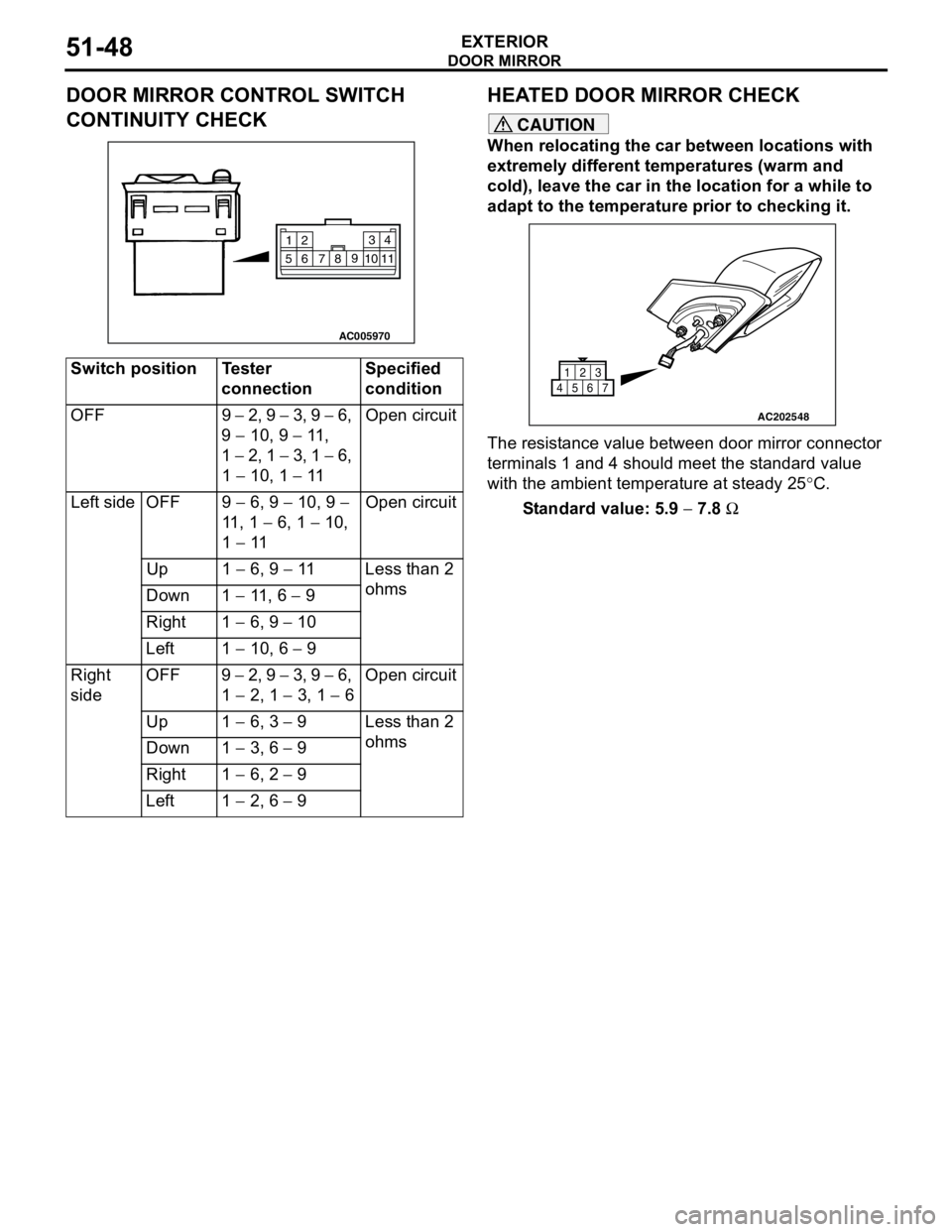
DOOR MIRROR CONTROL SWITCH
CONTINUITY CHECKHEATED DOOR MIRROR CHECK
CAUTION
When relocating the car between locations with
extremely different temperatures (warm and
cold), leave the car in the location for a while to
adapt to the temperature prior to checking it.
The resistance value between door mirror connector
terminals 1 and 4 should meet the standard value
with the ambient temperature at steady 25°C.
Standard value: 5.9 − 7.8 Ω Switch position Tester
connectionSpecified
condition
OFF 9 − 2, 9 − 3, 9 − 6,
9 − 10, 9 − 11 ,
1 − 2, 1 − 3, 1 − 6,
1 − 10, 1 − 11Open circuit
Left side OFF 9 − 6, 9 − 10, 9 −
11 , 1 − 6, 1 − 10,
1 − 11Open circuit
Up 1 − 6, 9 − 11 Less than 2
ohms
Down 1 − 11 , 6 − 9
Right 1 − 6, 9 − 10
Left 1 − 10, 6 − 9
Right
sideOFF 9 − 2, 9 − 3, 9 − 6,
1 − 2, 1 − 3, 1 − 6Open circuit
Up 1 − 6, 3 − 9 Less than 2
ohms
Down 1 − 3, 6 − 9
Right 1 − 6, 2 − 9
Left 1 − 2, 6 − 9
AC005970
2
14 3
5109
8
7 611
AC202548
1
456723
Page 387 of 788

52-1
GROUP 52
INTERIOR AND
SUPPLEMENTAL
RESTRAINT
SYSTEM(SRS)
CONTENTS
INTERIOR . . . . . . . . . . . . . . . . . . . . . . . . . . . . . . . . . . . . . . . . . .52A
SUPPLEMENTAL RESTRAINT SYSTEM (SRS) . . . . . . . . . . . .52B
Page 388 of 788

NOTES
Page 389 of 788
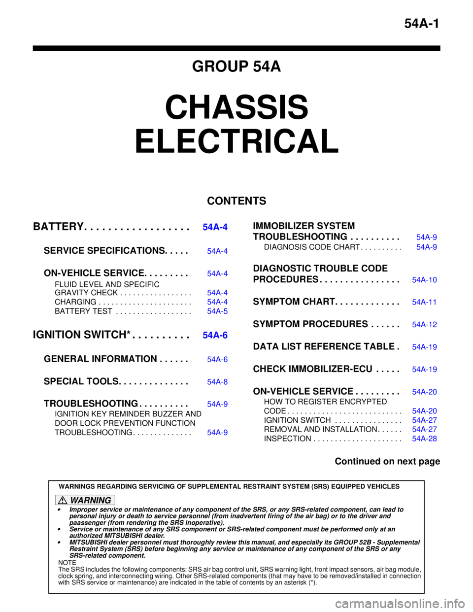
54A-1
GROUP 54A
CHASSIS
ELECTRICAL
CONTENTS
BATTERY. . . . . . . . . . . . . . . . . .
54A-4
SERVICE SPECIFICATIONS. . . . .
54A-4
ON-VEHICLE SERVICE. . . . . . . . .54A-4
FLUID LEVEL AND SPECIFIC
GRAVITY CHECK . . . . . . . . . . . . . . . . . 54A-4
CHARGING . . . . . . . . . . . . . . . . . . . . . . 54A-4
BATTERY TEST . . . . . . . . . . . . . . . . . . 54A-5
IGNITION SWITCH* . . . . . . . . . .54A-6
GENERAL INFORMATION . . . . . .
54A-6
SPECIAL TOOLS. . . . . . . . . . . . . .54A-8
TROUBLESHOOTING . . . . . . . . . .54A-9
IGNITION KEY REMINDER BUZZER AND
DOOR LOCK PREVENTION FUNCTION
TROUBLESHOOTING . . . . . . . . . . . . . . 54A-9
IMMOBILIZER SYSTEM
TROUBLESHOOTING . . . . . . . . . .
54A-9
DIAGNOSIS CODE CHART . . . . . . . . . . 54A-9
DIAGNOSTIC TROUBLE CODE
PROCEDURES . . . . . . . . . . . . . . . .
54A-10
SYMPTOM CHART. . . . . . . . . . . . .54A-11
SYMPTOM PROCEDURES . . . . . .54A-12
DATA LIST REFERENCE TABLE .54A-19
CHECK IMMOBILIZER-ECU . . . . .54A-19
ON-VEHICLE SERVICE . . . . . . . . .54A-20
HOW TO REGISTER ENCRYPTED
CODE . . . . . . . . . . . . . . . . . . . . . . . . . . . 54A-20
IGNITION SWITCH . . . . . . . . . . . . . . . . 54A-27
REMOVAL AND INSTALLATION . . . . . . 54A-27
INSPECTION . . . . . . . . . . . . . . . . . . . . . 54A-28
Continued on next page
WARNINGS REGARDING SERVICING OF SUPPLEMENTAL RESTRAINT SYSTEM (SRS) EQUIPPED VEHICLES
WARNING
•Improper service or maintenance of any component of the SRS, or any SRS-related component, can lead to
personal injury or death to service personnel (from inadvertent firing of the air bag) or to the driver and
paassenger (from rendering the SRS inoperative).
•Service or maintenance of any SRS component or SRS-related component must be performed only at an
authorized MITSUBISHI dealer.
•MITSUBISHI dealer personnel must thoroughly review this manual, and especially its GROUP 52B - Supplemental
Restraint System (SRS) before beginning any service or maintenance of any component of the SRS or any
SRS-related component.
NOTE
The SRS includes the following components: SRS air bag control unit, SRS warning light, front impact sensors, air bag module,
clock spring, and interconnecting wiring. Other SRS-related components (that may have to be removed/installed in connection
with SRS service or maintenance) are indicated in the table of contents by an asterisk (*).
Page 390 of 788
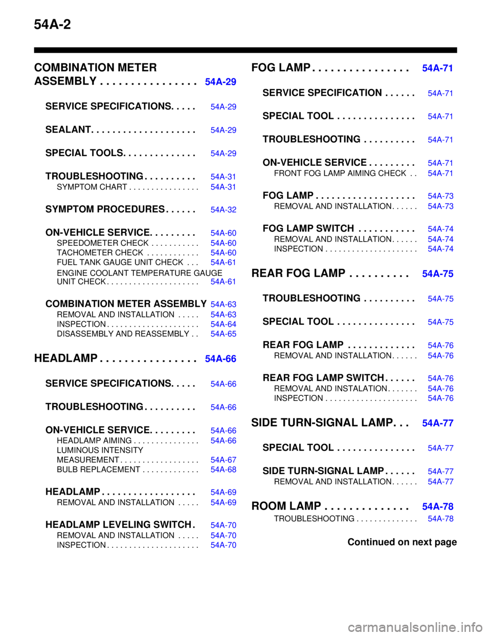
54A-2
COMBINATION METER
ASSEMBLY . . . . . . . . . . . . . . . .
54A-29
SERVICE SPECIFICATIONS. . . . .
54A-29
SEALANT. . . . . . . . . . . . . . . . . . . .54A-29
SPECIAL TOOLS. . . . . . . . . . . . . .54A-29
TROUBLESHOOTING . . . . . . . . . .54A-31
SYMPTOM CHART . . . . . . . . . . . . . . . . 54A-31
SYMPTOM PROCEDURES . . . . . .54A-32
ON-VEHICLE SERVICE. . . . . . . . .54A-60
SPEEDOMETER CHECK . . . . . . . . . . . 54A-60
TACHOMETER CHECK . . . . . . . . . . . . 54A-60
FUEL TANK GAUGE UNIT CHECK . . . 54A-61
ENGINE COOLANT TEMPERATURE GAUGE
UNIT CHECK . . . . . . . . . . . . . . . . . . . . . 54A-61
COMBINATION METER ASSEMBLY54A-63
REMOVAL AND INSTALLATION . . . . . 54A-63
INSPECTION . . . . . . . . . . . . . . . . . . . . . 54A-64
DISASSEMBLY AND REASSEMBLY . . 54A-65
HEADLAMP . . . . . . . . . . . . . . . .54A-66
SERVICE SPECIFICATIONS. . . . .
54A-66
TROUBLESHOOTING . . . . . . . . . .54A-66
ON-VEHICLE SERVICE. . . . . . . . .54A-66
HEADLAMP AIMING . . . . . . . . . . . . . . . 54A-66
LUMINOUS INTENSITY
MEASUREMENT . . . . . . . . . . . . . . . . . . 54A-67
BULB REPLACEMENT . . . . . . . . . . . . . 54A-68
HEADLAMP . . . . . . . . . . . . . . . . . .54A-69
REMOVAL AND INSTALLATION . . . . . 54A-69
HEADLAMP LEVELING SWITCH .54A-70
REMOVAL AND INSTALLATION . . . . . 54A-70
INSPECTION . . . . . . . . . . . . . . . . . . . . . 54A-70
FOG LAMP . . . . . . . . . . . . . . . . 54A-71
SERVICE SPECIFICATION . . . . . .
54A-71
SPECIAL TOOL . . . . . . . . . . . . . . .54A-71
TROUBLESHOOTING . . . . . . . . . .54A-71
ON-VEHICLE SERVICE . . . . . . . . .54A-71
FRONT FOG LAMP AIMING CHECK . . 54A-71
FOG LAMP . . . . . . . . . . . . . . . . . . .54A-73
REMOVAL AND INSTALLATION . . . . . . 54A-73
FOG LAMP SWITCH . . . . . . . . . . .54A-74
REMOVAL AND INSTALLATION . . . . . . 54A-74
INSPECTION . . . . . . . . . . . . . . . . . . . . . 54A-74
REAR FOG LAMP . . . . . . . . . . 54A-75
TROUBLESHOOTING . . . . . . . . . .
54A-75
SPECIAL TOOL . . . . . . . . . . . . . . .54A-75
REAR FOG LAMP . . . . . . . . . . . . .54A-76
REMOVAL AND INSTALLATION . . . . . . 54A-76
REAR FOG LAMP SWITCH . . . . . .54A-76
REMOVAL AND INSTALATION . . . . . . . 54A-76
INSPECTION . . . . . . . . . . . . . . . . . . . . . 54A-76
SIDE TURN-SIGNAL LAMP. . . 54A-77
SPECIAL TOOL . . . . . . . . . . . . . . .
54A-77
SIDE TURN-SIGNAL LAMP . . . . . .54A-77
REMOVAL AND INSTALLATION . . . . . . 54A-77
ROOM LAMP . . . . . . . . . . . . . . 54A-78
TROUBLESHOOTING . . . . . . . . . . . . . . 54A-78
Continued on next page