MITSUBISHI LANCER 2005 Workshop Manual
Manufacturer: MITSUBISHI, Model Year: 2005, Model line: LANCER, Model: MITSUBISHI LANCER 2005Pages: 788, PDF Size: 45.98 MB
Page 361 of 788
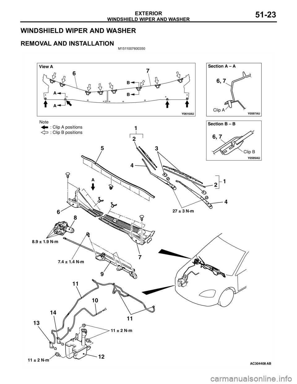
WINDSHIELD WIPER AND WASHER
EXTERIOR51-23
WINDSHIELD WIPER AND WASHER
REMOVAL AND INSTALLATIONM1511007600350
Y0597AU
Y0616AU
Y0599AU
AC304408AB
Section B – B Section A – A
View A
A A
AB
B
Clip A
Clip B
6, 7
6, 7
67
3
2 5
6
7 8
9
10 11
11
12 1314
27 ± 3 N·m
8.9 ± 1.9 N·m
11 ± 2 N·m
Note
: Clip A positions
: Clip B positions
11 ± 2 N·m
7.4 ± 1.4 N·m
2
1
1 4
4
Page 362 of 788
WINDSHIELD WIPER AND WASHER
EXTERIOR51-24
NOTE: For removal and installation of the wiper and
washer switch, refer to GROUP 54A, Column switch
P.54A-87.
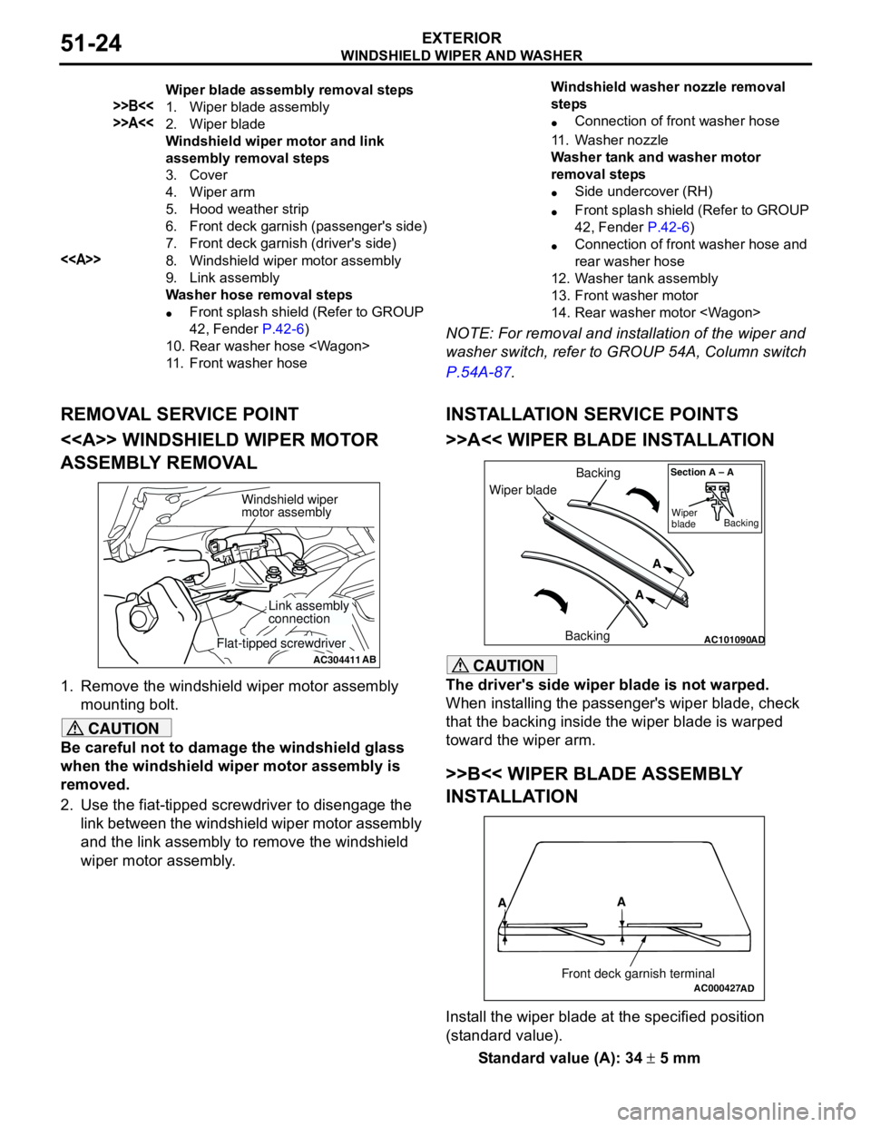
REMOVAL SERVICE POINT
<> WINDSHIELD WIPER MOTOR
ASSEMBLY REMOVAL
1. Remove the windshield wiper motor assembly
mounting bolt.
CAUTION
Be careful not to damage the windshield glass
when the windshield wiper motor assembly is
removed.
2. Use the fiat-tipped screwdriver to disengage the
link between the windshield wiper motor assembly
and the link assembly to remove the windshield
wiper motor assembly.
INSTALLATION SERVICE POINTS
>>A<< WIPER BLADE INSTALLATION
CAUTION
The driver's side wiper blade is not warped.
When installing the passenger's wiper blade, check
that the backing inside the wiper blade is warped
toward the wiper arm.
>>B<< WIPER BLADE ASSEMBLY
INSTALLATION
Install the wiper blade at the specified position
(standard value).
Standard value (A): 34 ± 5 mm
Wiper blade assembly removal steps
>>B<<1. Wiper blade assembly
>>A<<2. Wiper blade
Windshield wiper motor and link
assembly removal steps
3. Cover
4. Wiper arm
5. Hood weather strip
6. Front deck garnish (passenger's side)
7. Front deck garnish (driver's side)
<>8. Windshield wiper motor assembly
9. Link assembly
Washer hose removal steps
•Front splash shield (Refer to GROUP
42, Fender P.42-6)
10. Rear washer hose
11. Front washer hoseWindshield washer nozzle removal
steps
•Connection of front washer hose
11. Washer nozzle
Washer tank and washer motor
removal steps
•Side undercover (RH)
•Front splash shield (Refer to GROUP
42, Fender P.42-6)
•Connection of front washer hose and
rear washer hose
12. Washer tank assembly
13. Front washer motor
14. Rear washer motor
AC304411AB
Windshield wiper
motor assembly
Link assembly
connection
Flat-tipped screwdriverAC101090AD
Wiper bladeBacking
BackingA
A
Section A – A
Wiper
bladeBacking
AC000427
A
A
Front deck garnish terminalAD
Page 363 of 788
WINDSHIELD WIPER AND WASHER
EXTERIOR51-25
INSPECTIONM1511007700313
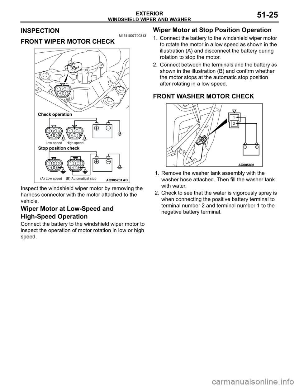
FRONT WIPER MOTOR CHECK
Inspect the windshield wiper motor by removing the
harness connector with the motor attached to the
vehicle.
Wiper Motor at Low-Speed and
High-Speed Operation
Connect the battery to the windshield wiper motor to
inspect the operation of motor rotation in low or high
speed.
Wiper Motor at Stop Position Operation
1. Connect the battery to the windshield wiper motor
to rotate the motor in a low speed as shown in the
illustration (A) and disconnect the battery during
rotation to stop the motor.
2. Connect between the terminals and the battery as
shown in the illustration (B) and confirm whether
the motor stops at the automatic stop position
after rotating in a low speed.
FRONT WASHER MOTOR CHECK
1. Remove the washer tank assembly with the
washer hose attached. Then fill the washer tank
with water.
2. Check to see that the water is vigorously spray is
when connecting the positive battery terminal to
terminal number 2 and terminal number 1 to the
negative battery terminal.
1
423
5
1
423
51
423
5
1
423
5
AC305201
1
423
5
Check operation
Low speed High speed
(A) Low speed (B) Automatical stop
Stop position check
AB
1
2
AC005891
Page 364 of 788
WINDSHIELD WIPER AND WASHER
EXTERIOR51-26
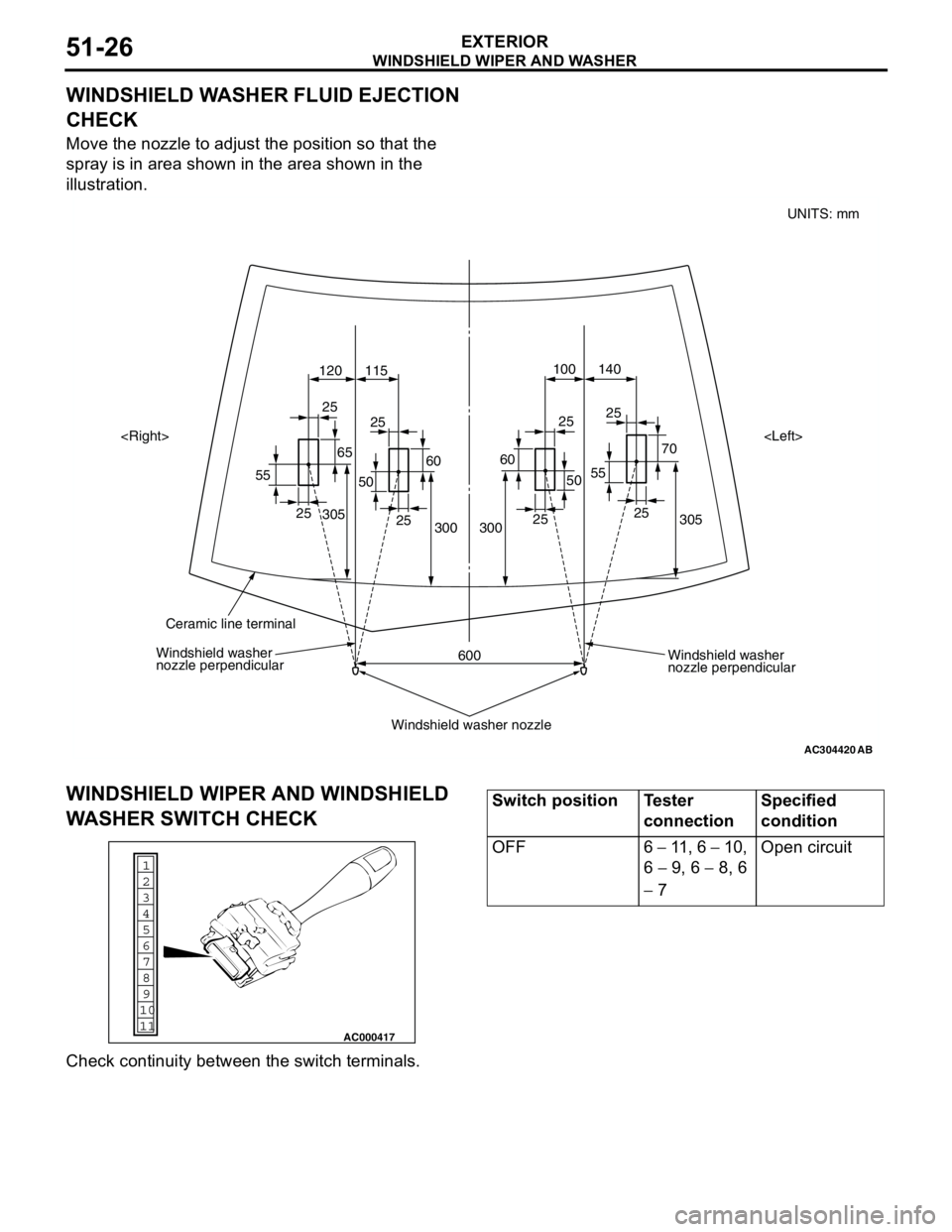
WINDSHIELD WASHER FLUID EJECTION
CHECK
Move the nozzle to adjust the position so that the
spray is in area shown in the area shown in the
illustration.
WINDSHIELD WIPER AND WINDSHIELD
WASHER SWITCH CHECK
Check continuity between the switch terminals.
AC304420
305 70 25
55140 100
120 115
305
300
600 300252525
25
25
25 25
55
6560
50
60
50
AB
Windshield washer
nozzle perpendicular Windshield washer
nozzle perpendicular
Windshield washer nozzle
Ceramic line terminal
UNITS: mm
1
6
8
11 109 7
5 4
3
2
AC000417
Switch position Tester
connectionSpecified
condition
OFF 6 − 11 , 6 − 10,
6 − 9, 6 − 8, 6
− 7Open circuit
Page 365 of 788
WINDSHIELD WIPER AND WASHER
EXTERIOR51-27
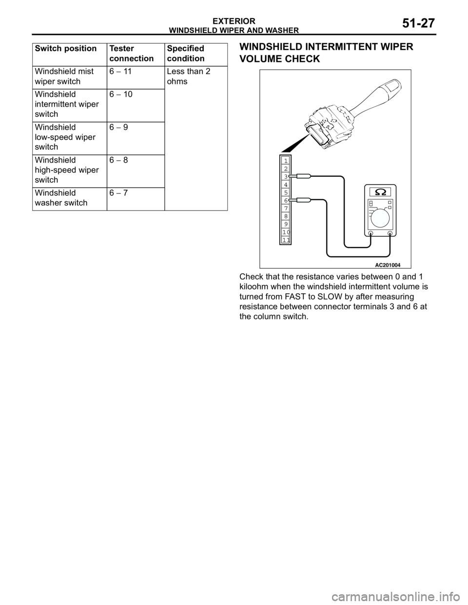
WINDSHIELD INTERMITTENT WIPER
VOLUME CHECK
Check that the resistance varies between 0 and 1
kiloohm when the windshield intermittent volume is
turned from FAST to SLOW by after measuring
resistance between connector terminals 3 and 6 at
the column switch. Windshield mist
wiper switch6 − 11 Less than 2
ohms
Windshield
intermittent wiper
switch6 − 10
Windshield
low-speed wiper
switch6 − 9
Windshield
high-speed wiper
switch6 − 8
Windshield
washer switch6 − 7 Switch position Tester
connectionSpecified
condition
1
6
8
11 109 7
5 4 3
2
AC201004
Page 366 of 788

REAR WIPER AND WASHER
EXTERIOR51-28
REAR WIPER AND WASHER
GENERAL INFORMATIONM1511000100525
REAR WIPER AND WASHER OPERATION
Rear Wiper Operation
•If the rear wiper and washer switch is turned to
"INT" position with the ignition switch at "ACC" or
"ON" position, the ETACS-ECU turns ON the rear
wiper drive signal for three seconds
(approximately two cycles), then 7.4 seconds
later the intermittent motion operates every eight
seconds. If the selector lever is moved to the "R"
position when the rear wiper and washer switch is
turned to the "INT" position and the ignition
switch is at the "ACC" or "ON" position, the inhibitor switch "R" turns ON. One second later,
the ETACS-ECU turns ON the rear wiper drive
signal for three seconds (approximately two
cycles). Then, 7.4 seconds later, the intermittent
motion of eight seconds' cycle is restored.
Rear Washer Operation
•If the rear wiper and washer switch is turned to
the ON (washer) position with the ignition switch
at the "ACC" or "ON" position, the rear washer
ON signal is sent to the ETACS-ECU, causing the
rear wiper signal to turn on after 0.3 second. After
the rear washer switch signal turns off, the rear
wiper signal turns off in three seconds. If the rear
washer switch is turned to the ON position while
the rear wiper is in intermittent mode, the rear
washer works for that period when the washer
switch remains on. Then the rear wipers return to
the intermittent mode.
SERVICE SPECIFICATIONM1511000300336
TROUBLESHOOTINGM1511000700334
The rear wiper and washer are controlled by the
Smart Wiring System (SWS). For troubleshooting,
refer to GROUP 54B, Troubleshooting P.54B-17 or
GROUP 54C, Troubleshooting P.54C-4.
ON-VEHICLE SERVICEM1511000800472
CHECK OF REAR WIPER OPERATION
WHEN SELECTOR LEVER IS AT THE "R"
POSITION
1. When the selector lever is moved to the "R"
position with the rear wiper switch at the "INT"
position, the wiper should operate twice or three
times at low speed after approximately one
second.
2. If not, carry out the troubleshooting (Refer to
GROUP 54B, Troubleshooting P.54B-17 or
GROUP 54C, Troubleshooting P.54C-4). ItemStandard value
Rear wiper blade park position mm 42 ± 5
Page 367 of 788
REAR WIPER AND WASHER
EXTERIOR51-29
REAR WIPER AND WASHER
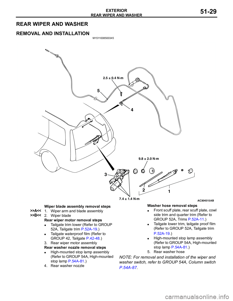
REMOVAL AND INSTALLATION
M1511008500345
NOTE: For removal and installation of the wiper and
washer switch, refer to GROUP 54A, Column switch
P.54A-87.
AC304515
2.5 ± 0.4 N·m
9.8 ± 2.0 N·m
7.4 ± 1.4 N·m
3
2
1 4
5
AB
Wiper blade assembly removal steps
>>A<<1. Wiper arm and blade assembly
>>B<<2. Wiper blade
Rear wiper motor removal steps
•Tailgate trim lower (Refer to GROUP
52A, Tailgate trim P.52A-19.)
•Tailgate waterproof film (Refer to
GROUP 42, Tailgate P.42-48.)
3. Rear wiper motor assembly
Rear washer nozzle removal steps
•High-mounted stop lamp assembly
(Refer to GROUP 54A, High-mounted
stop lamp P.54A-81.)
4. Rear washer nozzleWasher hose removal steps
•Front scuff plate, rear scuff plate, cowl
side trim and quarter trim (Refer to
GROUP 52A, Trims P.52A-11.)
•Tailgate lower trim, tailgate proof film
(Refer to GROUP 52A, Tailgate trim
P.52A-19.)
•High-mounted stop lamp assembly
(Refer to GROUP 54A, High-mounted
stop lamp P.54A-81.)
5. Rear washer hose
Page 368 of 788
REAR WIPER AND WASHER
EXTERIOR51-30
INSTALLATION SERVICE POINTS
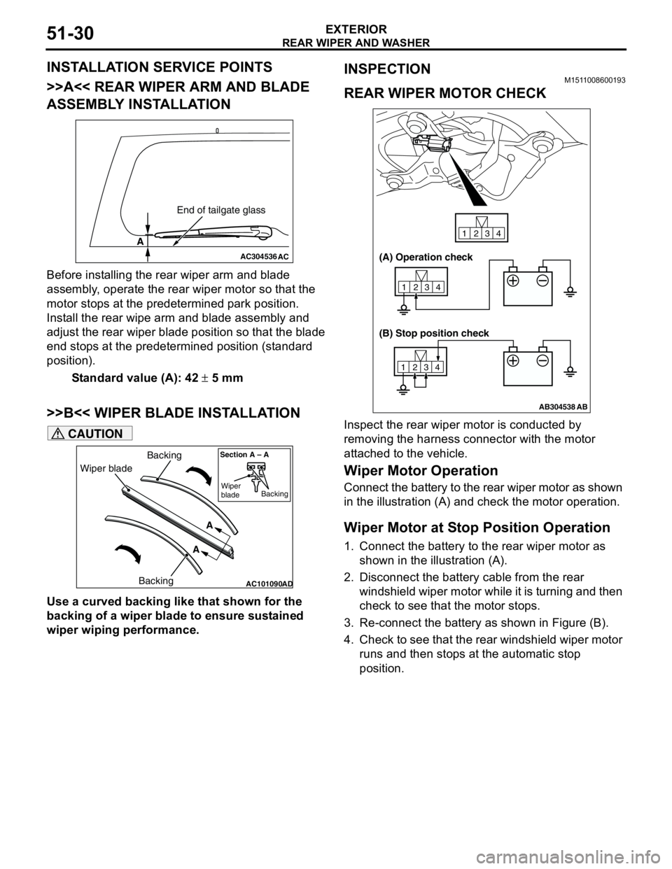
>>A<< REAR WIPER ARM AND BLADE
ASSEMBLY INSTALLATION
Before installing the rear wiper arm and blade
assembly, operate the rear wiper motor so that the
motor stops at the predetermined park position.
Install the rear wipe arm and blade assembly and
adjust the rear wiper blade position so that the blade
end stops at the predetermined position (standard
position).
Standard value (A): 42 ± 5 mm
>>B<< WIPER BLADE INSTALLATION
CAUTION
Use a curved backing like that shown for the
backing of a wiper blade to ensure sustained
wiper wiping performance.
INSPECTIONM1511008600193
REAR WIPER MOTOR CHECK
Inspect the rear wiper motor is conducted by
removing the harness connector with the motor
attached to the vehicle.
Wiper Motor Operation
Connect the battery to the rear wiper motor as shown
in the illustration (A) and check the motor operation.
Wiper Motor at Stop Position Operation
1. Connect the battery to the rear wiper motor as
shown in the illustration (A).
2. Disconnect the battery cable from the rear
windshield wiper motor while it is turning and then
check to see that the motor stops.
3. Re-connect the battery as shown in Figure (B).
4. Check to see that the rear windshield wiper motor
runs and then stops at the automatic stop
position.
AC304536
A
AC
End of tailgate glass
AC101090AD
Wiper bladeBacking
BackingA
A
Section A – A
Wiper
bladeBacking
AB304538
1234
1234
1234
AB
(A) Operation check
(B) Stop position check
Page 369 of 788
REAR WIPER AND WASHER
EXTERIOR51-31
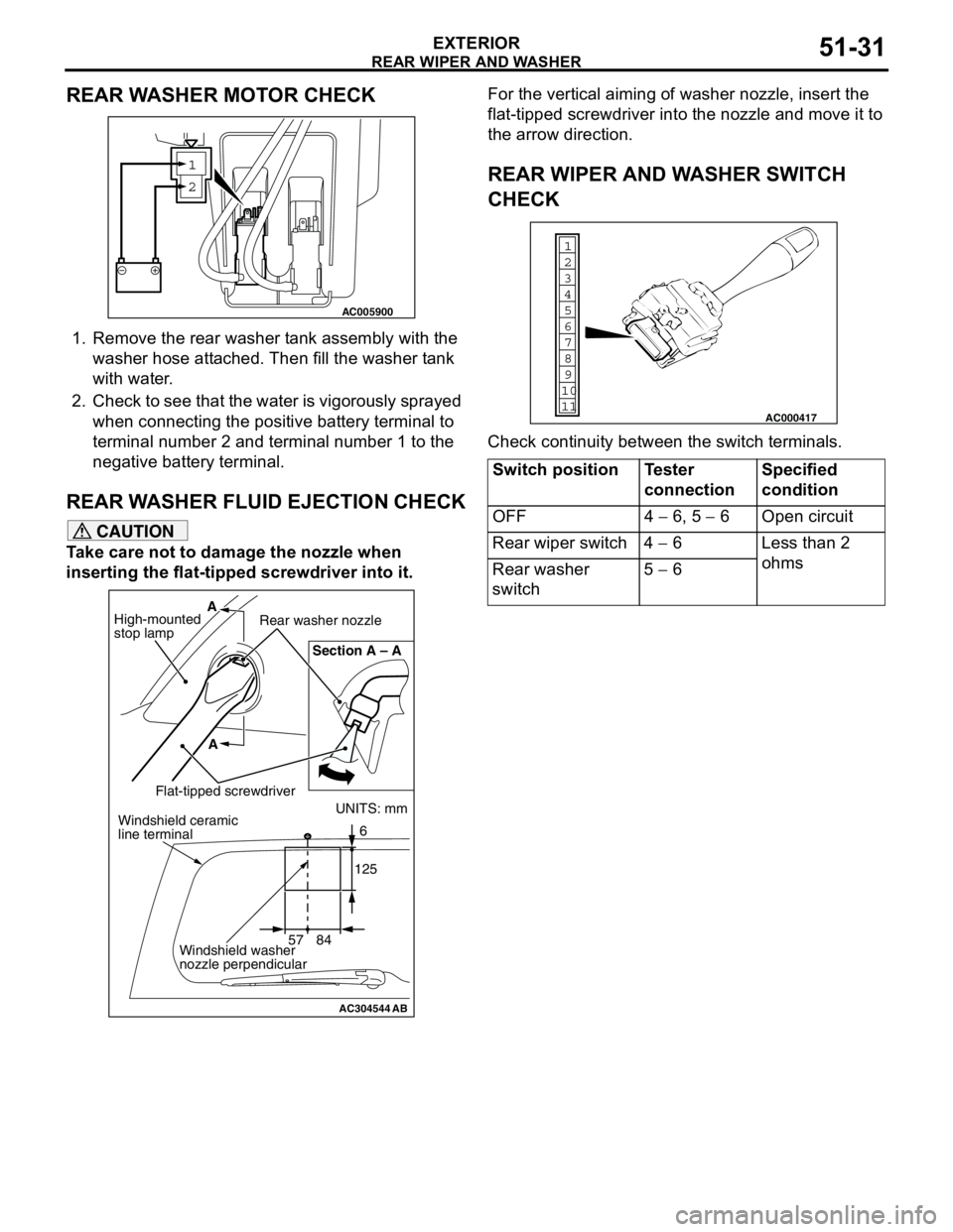
REAR WASHER MOTOR CHECK
1. Remove the rear washer tank assembly with the
washer hose attached. Then fill the washer tank
with water.
2. Check to see that the water is vigorously sprayed
when connecting the positive battery terminal to
terminal number 2 and terminal number 1 to the
negative battery terminal.
REAR WASHER FLUID EJECTION CHECK
CAUTION
Take care not to damage the nozzle when
inserting the flat-tipped screwdriver into it.For the vertical aiming of washer nozzle, insert the
flat-tipped screwdriver into the nozzle and move it to
the arrow direction.
REAR WIPER AND WASHER SWITCH
CHECK
Check continuity between the switch terminals.
1
2
AC005900
AC304544AB
UNITS: mm
57 841256 Section A – A
A A
High-mounted
stop lampRear washer nozzle
Flat-tipped screwdriverWindshield ceramic
line terminal
Windshield washer
nozzle perpendicular
Switch position Tester
connectionSpecified
condition
OFF 4 − 6, 5 − 6 Open circuit
Rear wiper switch 4 − 6 Less than 2
ohms
Rear washer
switch5 − 6
1
6
8
11 109 7
5 4
3
2
AC000417
Page 370 of 788
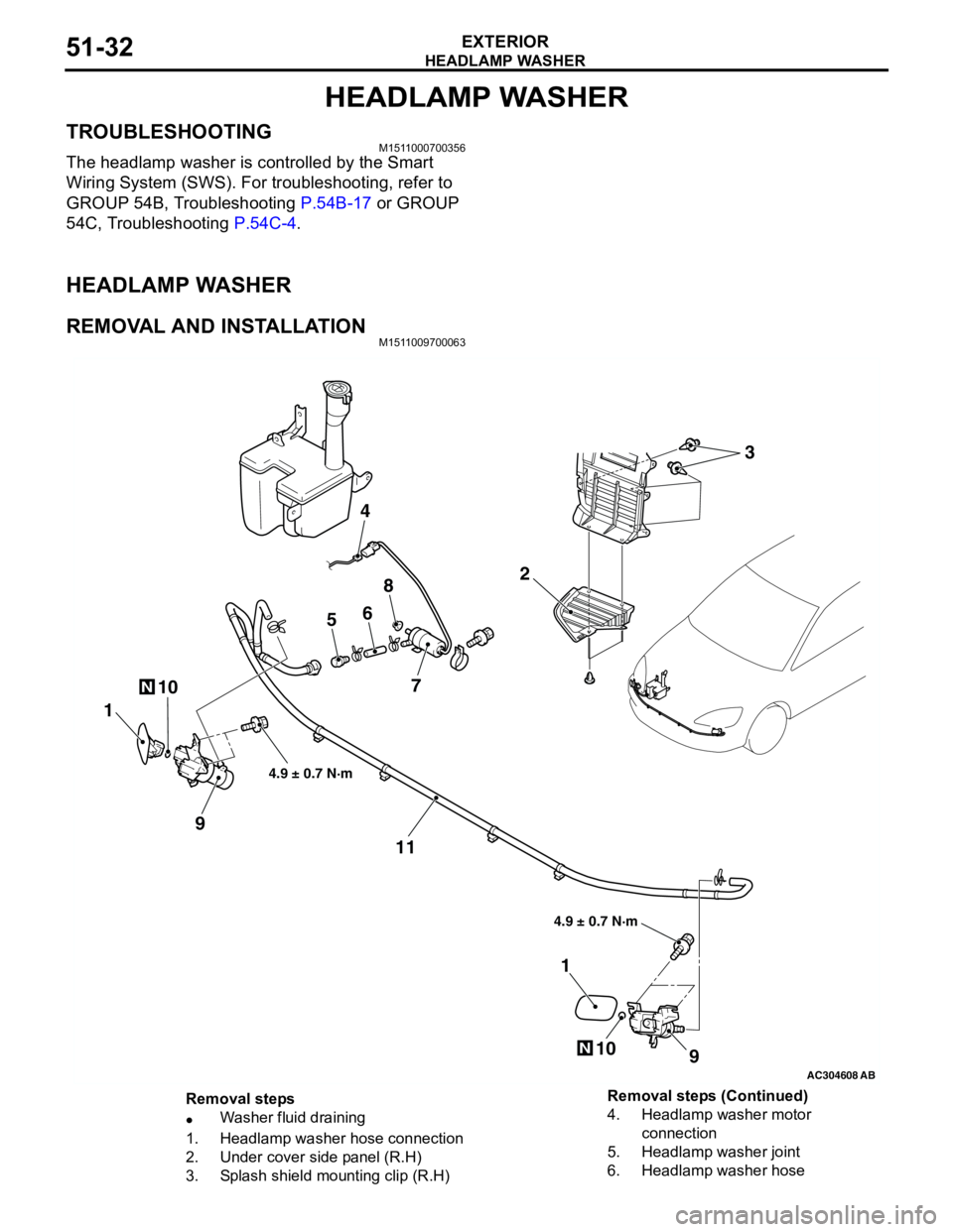
HEADLAMP WASHER
EXTERIOR51-32
HEADLAMP WASHER
TROUBLESHOOTINGM1511000700356
The headlamp washer is controlled by the Smart
Wiring System (SWS). For troubleshooting, refer to
GROUP 54B, Troubleshooting P.54B-17 or GROUP
54C, Troubleshooting P.54C-4.
HEADLAMP WASHER
REMOVAL AND INSTALLATIONM1511009700063
AC304608AB
10N
2
4
56
8
7
1
9
11
9
1
10N
4.9 ± 0.7 N·m 4.9 ± 0.7 N·m
3
Removal steps
•Washer fluid draining
1. Headlamp washer hose connection
2. Under cover side panel (R.H)
3. Splash shield mounting clip (R.H)4. Headlamp washer motor
connection
5. Headlamp washer joint
6. Headlamp washer hose Removal steps (Continued)