MITSUBISHI MONTERO 1987 1.G Workshop Manual
MONTERO 1987 1.G
MITSUBISHI
MITSUBISHI
https://www.carmanualsonline.info/img/19/7559/w960_7559-0.png
MITSUBISHI MONTERO 1987 1.G Workshop Manual
Trending: Vacuum, Fuse, oil reset, fuel tank capacity, Relay, torque, overdrive
Page 181 of 284
LIGHTING SYSTEM - Hazard Warning Switch 8-161
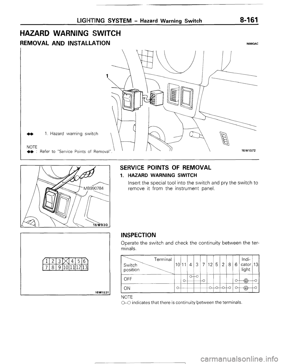
HAZARD WARNING
REMOVAL AND INSTALLATION NOBICLAC
16W1531
SERVOCE POINTS OF REMOVAL
1. HAZARD WARNING SWITCH
Insert the special tool into the switch and pry the switch to
remove it from the instrument panel.
INSPECTION
Operate the switch and check the continuity between the ter-
minals.
NOTE
CC indicates that there is continuity between the terminals.
STB Revision
Page 182 of 284
8-162 LIGHTING SYSTEM - Dimmer Control Switch
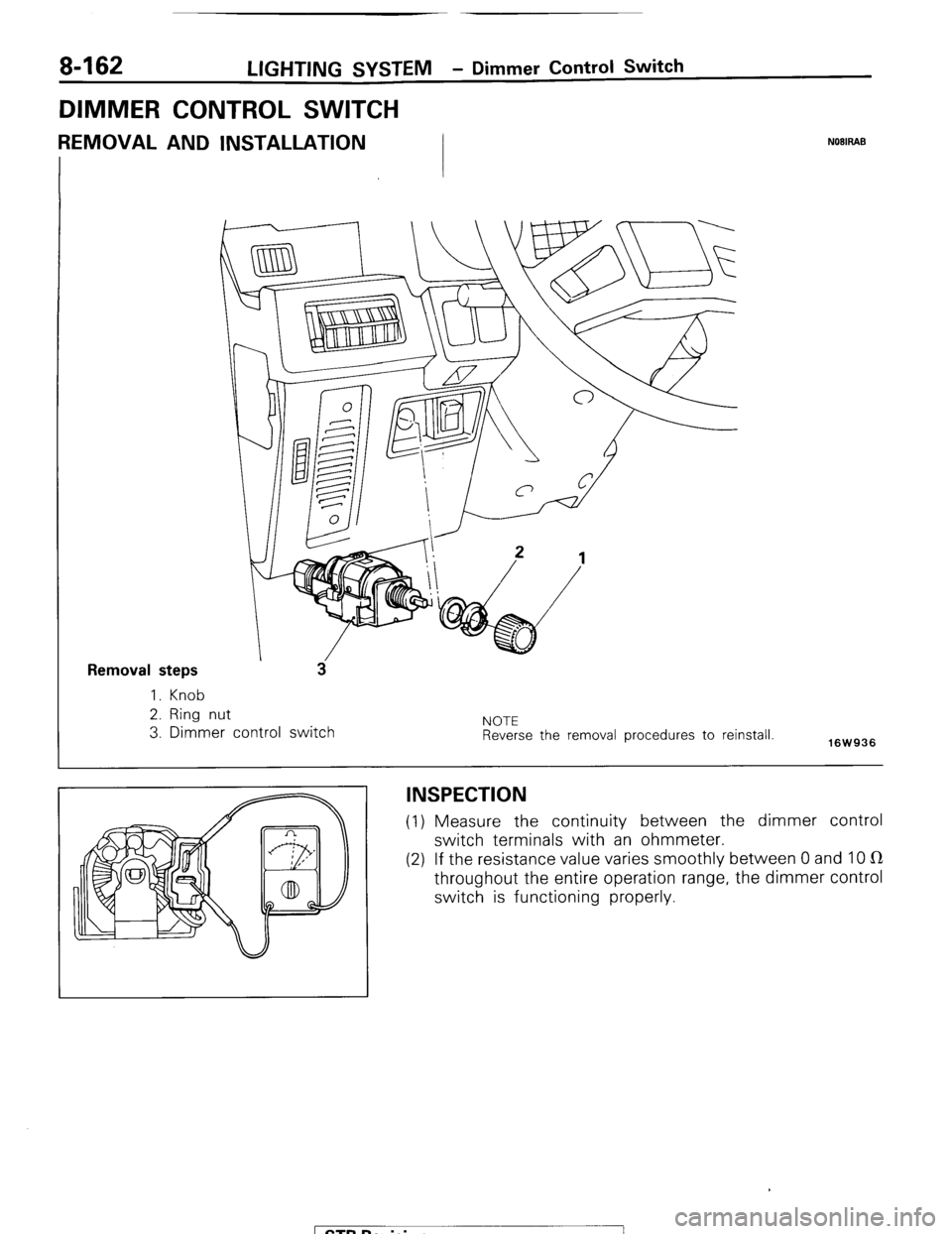
DIMMER CONTROL SWITCH
REMOVAL AND INSTALLATION NOBIRAB
Removal steps
1. Knob
2. Ring nut
3. Dimmer control switch NOTE
Reverse the removal procedures to reinstall.
16W936
INSPECTION
(1) Measure the continuity between the dimmer control
switch terminals with an ohmmeter.
(2) If the resistance value varies smoothly between 0 and 10 IR
throughout the entire operation range, the dimmer control
switch is functioning properly.
1 STB Revision
Page 183 of 284
WIPER AND WASHER SYSTEM -Specifications 8-163
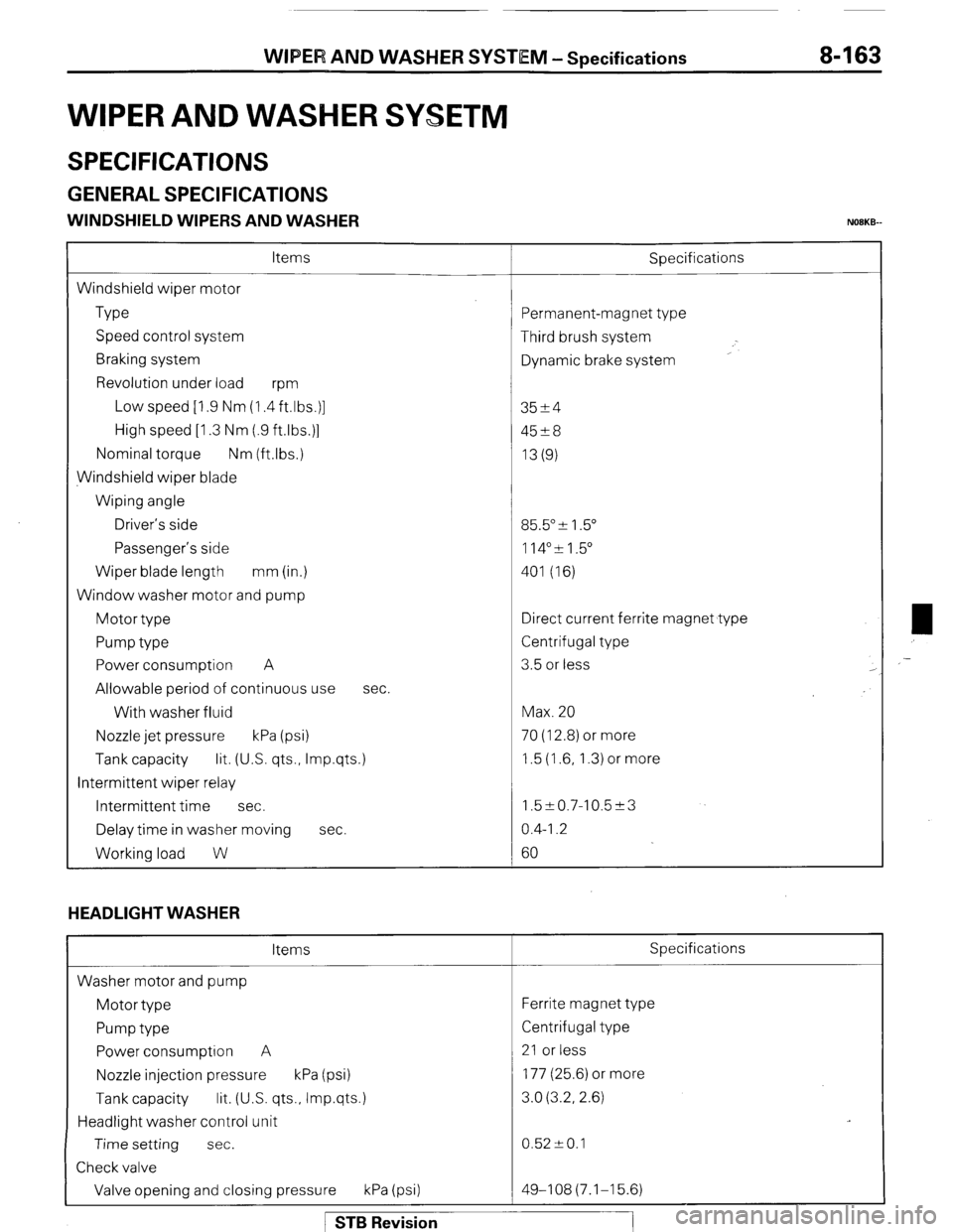
WIPER AND WASHER SYSETM
SPECIFICATIONS
GENERAL SPECIFICATIONS
WINDSHIELD WIPERS AND WASHER NOBKB-
Items
Windshield wiper motor
Type
Speed control system
Braking system
Revolution under load
wm
Low speed [I .9 Nm (1.4 ft.lbs.)]
High speed [I .3 Nm (.9 ftlbs.)]
Nominal torque Nm (ftlbs.)
Windshield wiper blade
Wiping angle
Driver’s side
Passenger’s side
Wiper blade length mm (in.)
Window washer motor and pump
Motor type
Pump type
Power consumption A
Allowable period of continuous use
With washer fluid
Nozzle jet pressure kPa (psi) Sbecifications
sec.
Tank capacity lit. (US. qts., Imp.qts.)
Intermittent wiper relay
Intermittent time sec.
Delay time in washer moving sec.
Working load W
HEADLIGHT WASHER
Items
Washer motor and pump
Motor type
Pump type
Power consumption A
Nozzle injection pressure kPa (psi)
Tank capacity lit. (U.S. qts., Imp.qts.)
Headlight washer control unit
Time setting sec.
Check valve
Valve opening and closing pressure kPa (psi) ‘ermanent-magnet type
Third brush system
Dynamic brake system
3524
45?8
13(g)
35.5” & 1.5”
114”51.5”
401 (16)
Iirect current ferrite magnet type
Zentrifugal type
3.5 or less
Max. 20
70 (12.8) or more
1.5 (1.6, 1.3) or more
1.5~0.7-10.5~3
0.4-I .2
60
Specifications
Ferrite magnet type
Centrifugal type
21 or less
177 (25.6) or more
3.0 (3.2, 2.6)
0.52 -+ 0.1
49-108(7.1-15.6) ,-
1 STB Revision
Page 184 of 284
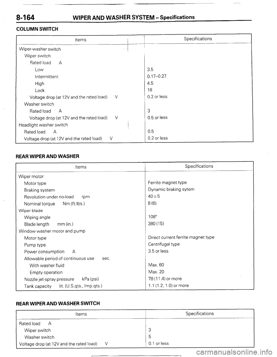
8-164 WIPER AND WASHER SYSTEM -Specifications
COLUMN SWITCH
L
Specifications
Wiper-washer switch
Wiper switch
Rated load A
Low
intermittent
High
Lock
Voltage drop (at
Washer switch
Rated load A
Voltage drop (at 2V and the rated load) V
2V and the rated load) V
/
Headlight washer switch I
Rated load A
Voltage drop (at 12V and the rated load) V
REAR WIPER AND WASHER
Items
Wiper motor
Motor type
Braking system
Revolution under no-load
m
Nominal torque Nm (ftlbs.)
Wiper blade
Wiping angle
Blade length mm (in.)
Window washer motor and pump
Motor type
Pump type
Power consumption A
Allowable period of continuous use
With washer fluid
Empty operation sec.
Nozzle jet-spray pressure kPa (psi) 78 (11.4) or more
Tank capacity lit. (U.S.qts., Imp.qts.) 1 .I (1.2, 1 .O) or more 3.5
0.17-0.27
4.5
18
0.2 or less
3
0.5 or less
0.5
0.2 or less
Specifications
Ferrite magnet type
Dynamic braking sytem
4025
8 (6)
108
380(15)
Direct current ferrite magnet type
Centrifugal type
3.5 or less
Max. 60
Max. 20
REAR WIPER AND WASHER SWITCH
Items Specifications
Rated load A
Wiper switch 3
Washer switch 5
Voltage drop (at 12V and the rated load) V 0.1 or less
1 STB Revision
Page 185 of 284
WIPER AND WASHER SYSETM - Specifications / Special TOOIS 8-165
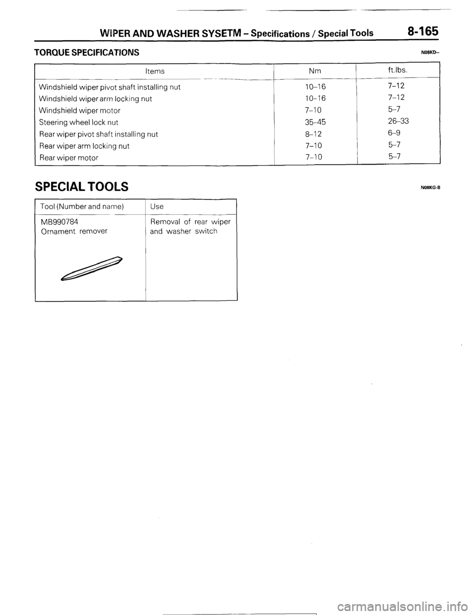
TORQUE SPECIFICATIONS N08KLb-
Items Nm
Windshield wiper pivot shaft installing nut
IO-16 Windshield wiper arm locking nut
IO-16 Windshield wiper motor
7-10 Steering wheel lock nut
35-45 Rear wiper pivot shaft installing nut
8-12 Rear wiper arm locking nut
7-10 Rear wioer motor
7-10
SPECIAL TOOLS NOEKG-B
1 STB Revision
Page 186 of 284
8-166 WIPER AND WASHER SYSTEM -Troubleshooting
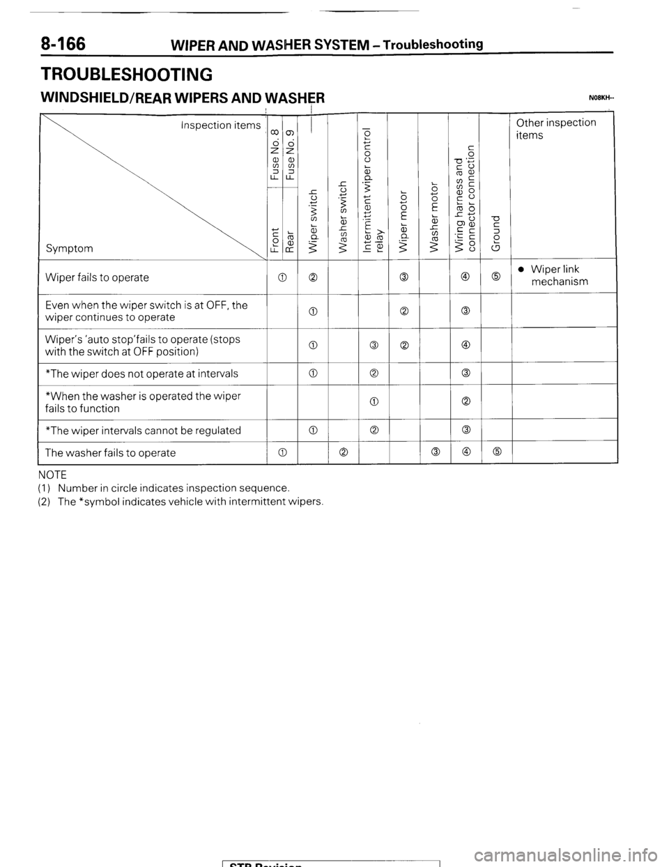
TROUBLESHOOTING
WINDSHIELD/REAR WIPERS AND WASHER N08KW
Symptom
Wiper fails to operate /
Inspection items co ~ Other inspectior
T items
2s +c
a, al E E
2 2 -0 ‘i;
&
Ll-LL
1 .-
1 0 ; 6%
Even when the wiper switch is at OFF, the
wiper continues to operate a 0 0
Wiper’s ‘auto stop’fails to operate (stops
vyith the switch at OFF position) 0 0 0 @
*The wiper does not operate at intervals 0 0 0
*When the washer is operated the wiper
fails to function 0 0
*The wiper intervals cannot be regulated 0 0 0
The washer fails to operate 0 0 0 @ 0
NOTE
(1) Number in circle indicates inspection sequence.
(2) The *symbol indicates vehicle with intermittent wipers
1 STB Revision
-7
Page 187 of 284
WIPER AND WASHER SYSTEM -Troubleshooting 8-167
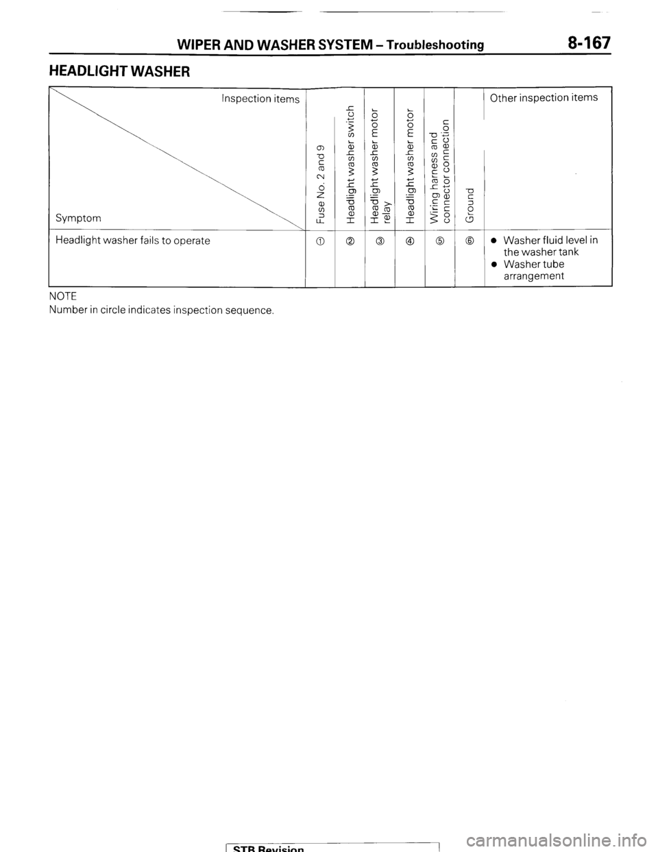
HEADLIGHT WASHER
Inspection items
Symptom
Headlight washer fails to operate
NOTE
Number in circle indicates inspection sequence. -
Other inspection items
1 STB Revision
Page 188 of 284
8468 WIPER AND WASHERS SYSTEM - Circuit Diagram
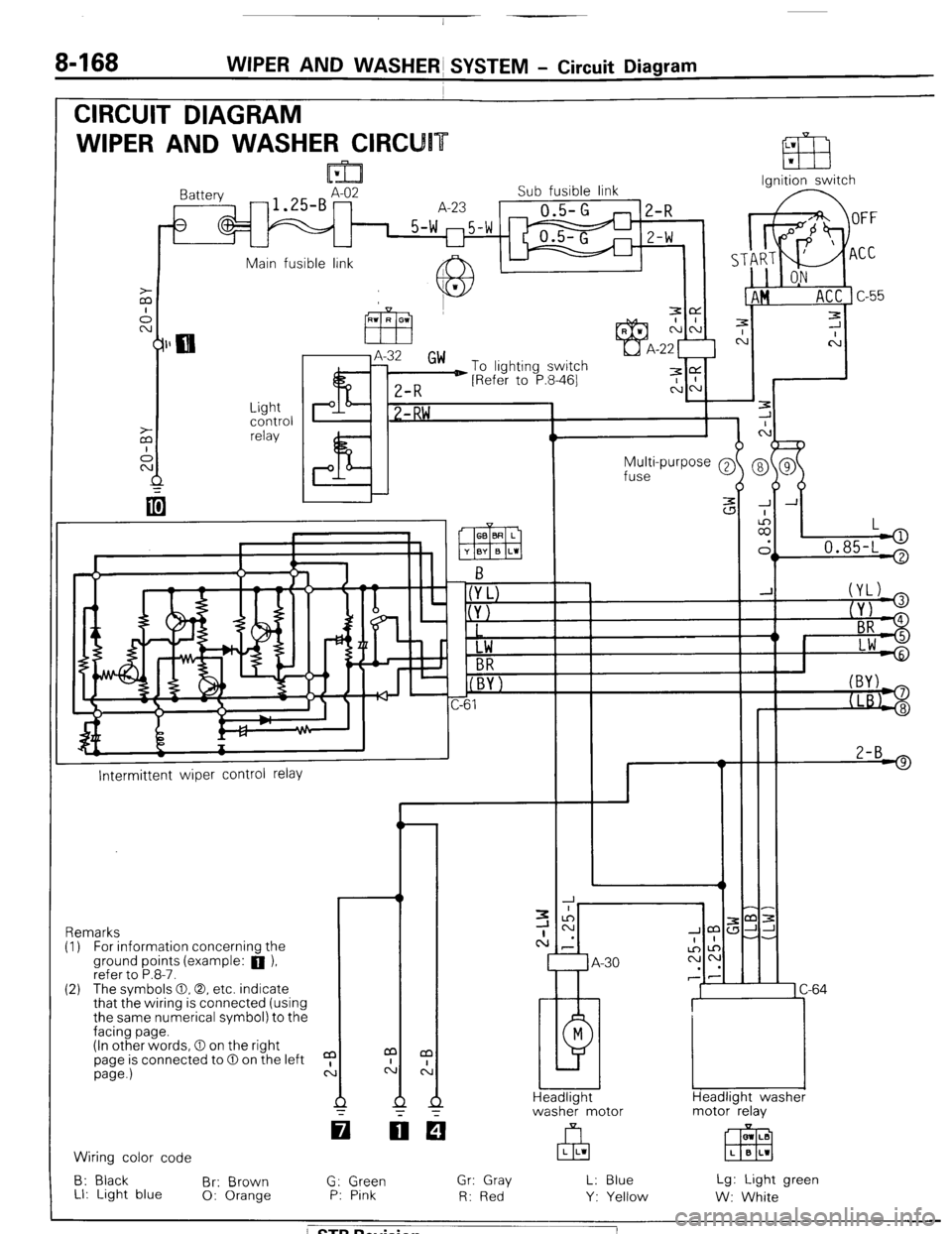
CIRCUIT DIAGRAM
WIPER AND WASHER CIRCU
Ignition switch
lattery
-1.SBAz2 Sub fusible link
A-23
0.5-G
1 5-w m5-w
U
2-R
Z-W
Main fusible link A IL
J.
c
7
C
-
-
-
-
-
-
J A
:
II,
L
.
> 0.85-L '
Light
control
relay P I? 1 -RW ,
Multi-purpose @
fuse
2-B 9
I--
Intermittent wiper control relay
-r ,m:
JJ-
-.
1 C-64
Headlight washer
motor relay Remarks
(I) For information concernina the
ground points (example: a ),
refer to P.8-7.
(2) The svmbols 0.0. etc. indicate
that the wiring is connected (using
the same numerical symbol) to the
facing page.
(In other words, 0 on the right
page is connected to 0 on the left
page.)
a
c: m LB
EEEI L B L1 Wiring color code
B: Black
Br: Brown
LI: Light blue 0: Orange G: Green
P: Pink Gr: Gray
R: Red L: Blue
Y: Yellow Lg: Light green
W: White
/ STB Revision
Page 189 of 284
WIPER AND WASHER SYSTEM - Circuit Diagram 8469
m Column switch -- Front-koer switch -1
Rear wiper and
washer switch
r I Headlight
washer
switch
o-(YL)
@JYJ
(+ BR
@- Lw
L B-l 2
w2-B
! )
1
L
(
7 A-14
1 B-07
81
M
A-58
>
1
GE&washer I
Rear wiper Front washer
motor Front wiper
motor motor
motor
37W124
/ STB Revision
Page 190 of 284
8-170 WIPER AND WASHER SYSTEM - Service Adjustment Procedures
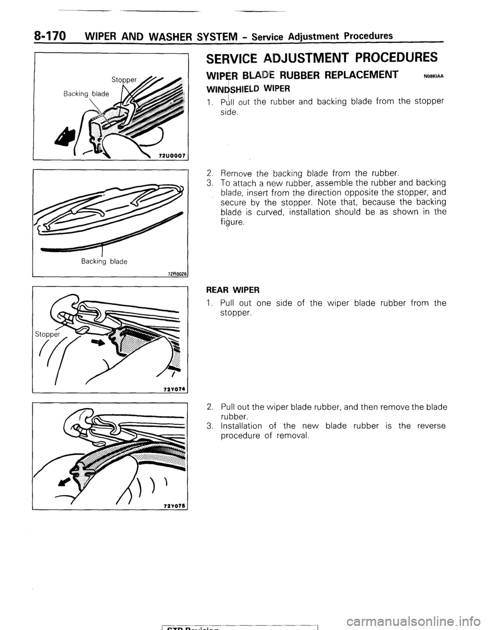
SERVICE ADJUSTMENT PROCEDURES
WIPE#l BLADE RUBBER REPLACEMENT
WINdSHIELD WIPER
NOBKIAA
1. Pull out the rubber and backing blade from the stopper
side.
Back&g blade
2. Remove the backing blade from the rubber.
3. To attach a new rubber, assemble the rubber and backing
blade, insert from the direction opposite the stopper, and
secure by the stopper. Note that, because the backing
blade is curved, installation should be as shown in the
figure.
REAR WIPER
1. Pull out one side of the wiper blade rubber from the
stopper.
2. Pull out the wiper blade rubber, and then remove the blade
rubber.
3. Installation of the new blade rubber is the reverse
procedure of removal.
( ST6 Revision
Trending: reset, wiring, hazard flasher unit, jump start, radiator cap, instrument panel, 4WD
