MITSUBISHI SPYDER 1990 Service Repair Manual
Manufacturer: MITSUBISHI, Model Year: 1990, Model line: SPYDER, Model: MITSUBISHI SPYDER 1990Pages: 2103, PDF Size: 68.98 MB
Page 1791 of 2103
S T E E R I N G Steerina Wheel and S h a f t
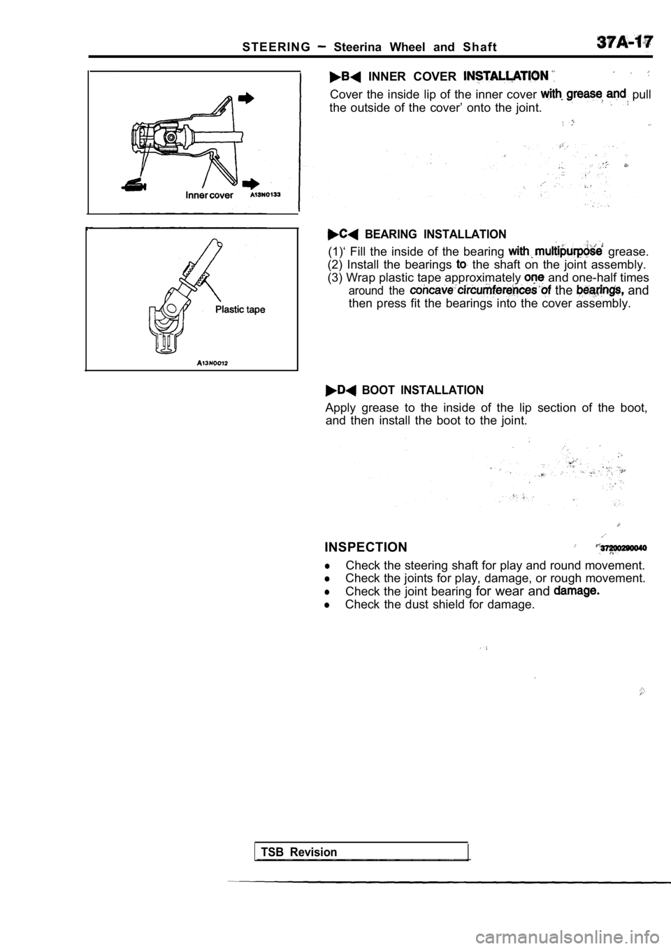
INNER COVER
Cover the inside lip of the inner cover pull
the outside of the cover’ onto the joint.
BEARING INSTALLATION
(1)‘ Fill the inside of the bearing grease.
(2) Install the bearings
the shaft on the joint assembly.
(3) Wrap plastic tape approximately
and one-half times
around the the and
then press fit the bearings into the cover assembly .
BOOT INSTALLATION
Apply grease to the inside of the lip section of th e boot,
and then install the boot to the joint.
INSPECTION
lCheck the steering shaft for play and round movemen t.
lCheck the joints for play, damage, or rough movemen t.
lCheck the joint bearing for wear and
lCheck the dust shield for damage.
TSB Revision
Page 1792 of 2103
STEERING Power Steering Gear.
POWER STEERING GEAR BOX
REMOVAL AND INSTALLATION
Engine (Non-turbo)>
Pre-removal OperationPower Steering Fluid Draining (Refer to Stabilizer Bar Removal (Refer to GROUP Stabilizer Bar.)l Washer Tank Removal(Refer to GROUP 51 Windshield Wiper andWasher.)
tive, risking serious driver injury.
Nm Nm Nm51-58
3720039007~
TSB Revision
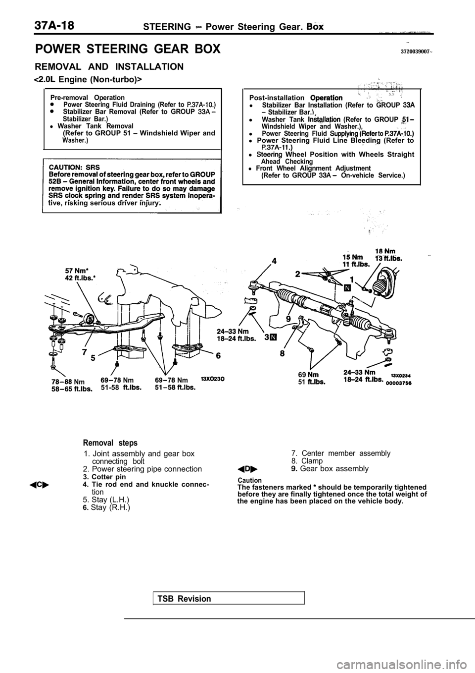
Removal steps
1. Joint assembly and gear boxconnecting bolt2. Power steering pipe connection
3. Cotter pin
4. Tie rod end and knuckle connec-
tion5. Stay (L.H.)
6. Stay (R.H.) Post-installation
lStabilizer Bar Installation (Refer to GROUP Stabilizer Bar.)lWasher Tank (Refer to GROUP Windshield Wiper and Washer.),lPower Steering Fluid l
Power Steering Fluid Line Bleeding (Refer to
l Wheel Position with Wheels StraightAhead Checkingl Front Wheel Alignment Adjustment
(Refer to GROUP On-vehicle Service.)
6951
7. Center member assembly
8. Clamp
Gear box assembly
CautionThe fasteners marked should be temporarily tightened
before they are finally tightened once the total we ight of
the engine has been placed on the vehicle body.
Page 1793 of 2103
STEERING Power Steering Gear
Engine (Turbo) and Engine>
CAUTION: SRSBefore removal of steering gear box, GROUP General Information, center front wheels and
remove ignition key. Failure to do so may damage
SRS clock spring and render SRS system inopera-
tive, risking serious driver injury.
Post-installationlStabilizer Bar Installation (Refer to GROUP Stabilizer Bar.)l Drive-belt Tension Adjustment Engine (Turbo): On-vehicle Engine; Refer to On-vehicle
l Fluid Supplying l Fluid (Refer to
.
l ‘Wheel Position Ahead Checking lFront Alignment Adjustment(Refer to GROUP
1523-26 Nm
24-33 Nm
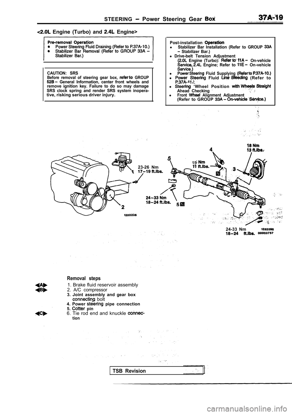
Removal steps
1. Brake fluid reservoir assembly
2. A/C compressor3. Joint assembly and gear box bolt 24-33 Nm4. Power pipe connection
5. pin
6. Tie rod end and knuckle
tion
TSB Revision
Page 1794 of 2103
STEERING Power Steerina
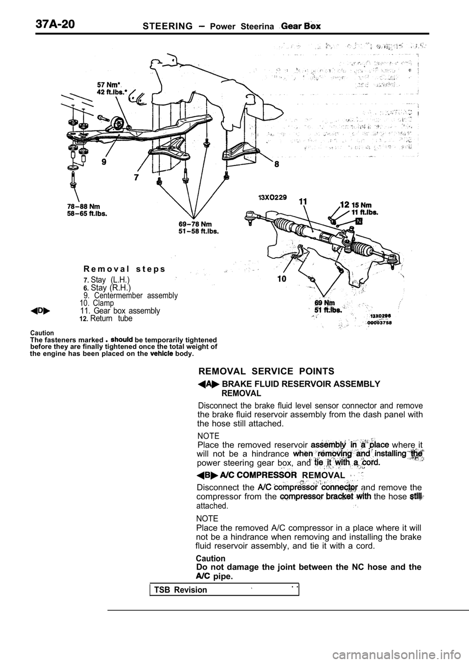
R e m o v a l s t e p s
7.Stay (L.H.)
6.Stay (R.H.)
Caution
9. Centermember assembly
10. Clamp
11. Gear box assembly12.Return tube
The fasteners marked l be temporarily tightened
before they are finally tightened once the total we ight of
the engine has been placed on the
body.
REMOVAL SERVICE POINTS
BRAKE FLUID RESERVOIR ASSEMBLY
REMOVAL
Disconnect the brake fluid level sensor connector a nd remove
the brake fluid reservoir assembly from the dash pa nel with
the hose still attached.
NOTE
Place the removed reservoir where it
will not be a hindrance
power steering gear box, and
REMOVAL
Disconnect the and remove the
compressor from the
the hose
attached.
NOTE
Place the removed A/C compressor in a place where i t will
not be a hindrance when removing and installing the brake
fluid reservoir assembly, and tie it with a cord.
Caution
Do not damage the joint between the NC hose and the
pipe.
TSB Revision. .
Page 1795 of 2103
STEERING, Power . . , , ,
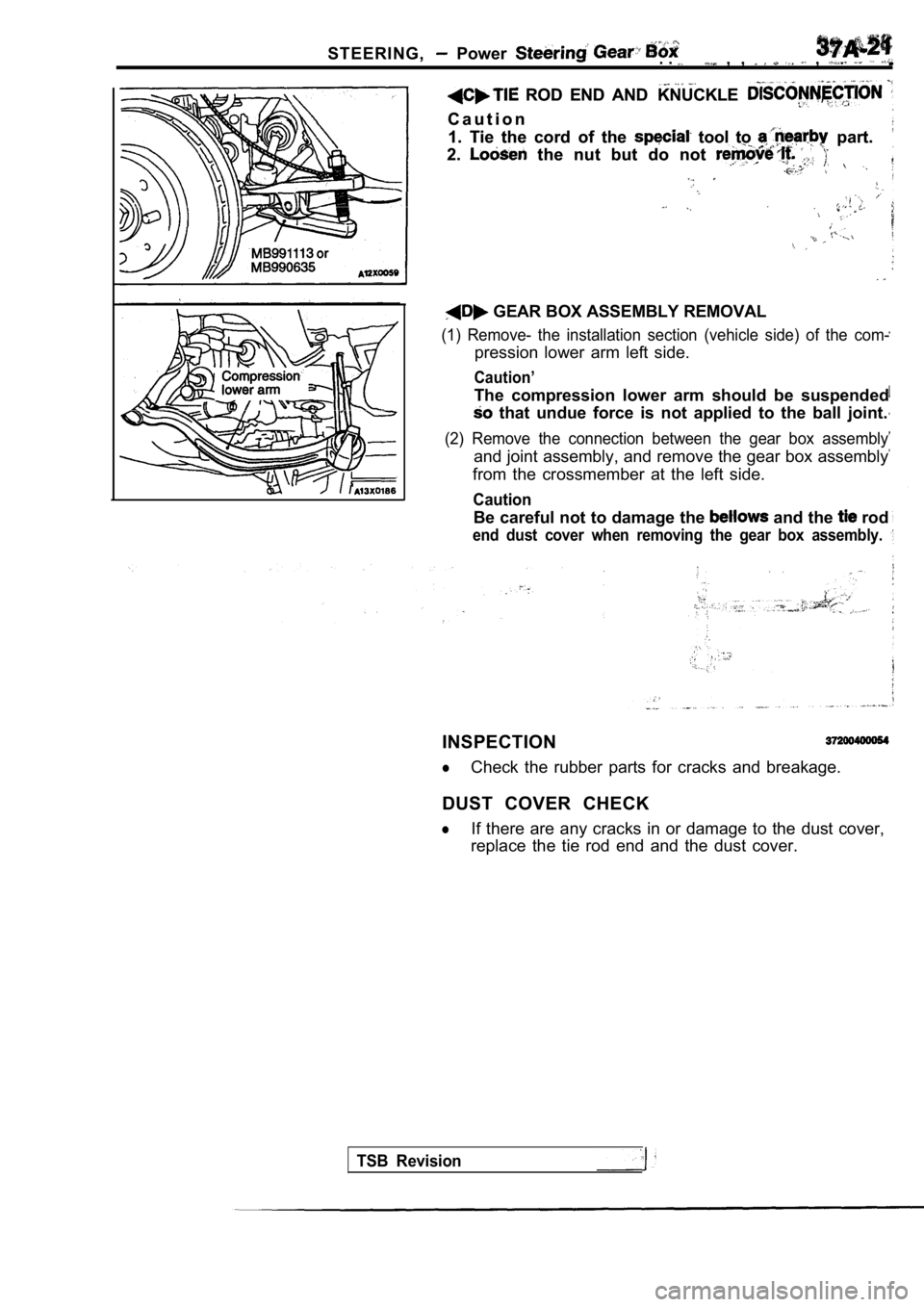
ROD END AND KNUCKLE ROD END AND KNUCKLE
C a u t i o n
C a u t i o n
1. Tie the cord of the
tool to part.
1. Tie the cord of the tool to part.
2.
the nut but do not 2. the nut but do not ,,
GEAR BOX ASSEMBLY REMOVAL
(1) Remove- the installation section (vehicle side) of the com-
pression lower arm left side.
Caution’
The compression lower arm should be suspended
that undue force is not applied to the ball joint.
(2) Remove the connection between the gear box asse mbly
and joint assembly, and remove the gear box assembly
from the crossmember at the left side.
Caution
Be careful not to damage the and the rod
end dust cover when removing the gear box assembly.
INSPECTION
lCheck the rubber parts for cracks and breakage.
DUST COVER CHECK
lIf there are any cracks in or damage to the dust co ver,
replace the tie rod end and the dust cover.
TSB Revision
Page 1796 of 2103
S T E E R I N G
TSB Revision
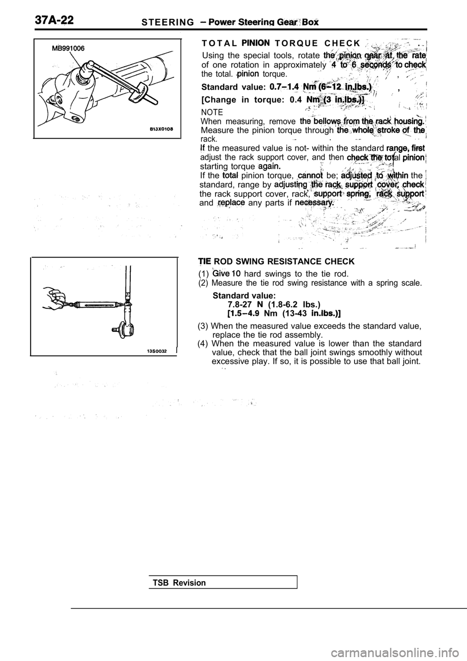
T O T A L T O R Q U E C H E C K .
Using the special tools, rotate
of one rotation in approximately
the total. torque. , ,
Standard value: ,
[Change in torque: 0.4
NOTE.
When measuring, remove
Measure the pinion torque through
rack. .
the measured value is not- within the standard
adjust the rack support cover, and then
starting torque
al
If the pinion torque, be; the
standard, range by
the rack support cover, rack,
and any parts if
ROD SWING RESISTANCE CHECK
(1)
hard swings to the tie rod.
(2) Measure the tie rod swing resistance with a spr ing scale.
Standard value:
7.8-27
(1.8-6.2 Ibs.)
Nm (13-43
(3) When the measured value exceeds the standard va lue,
replace the tie rod assembly.
(4) When the measured value is lower than the stand ard
value, check that the ball joint swings smoothly wi thout
excessive play. If so, it is possible to use that b all joint.
.
Page 1797 of 2103
Power Steering Gear
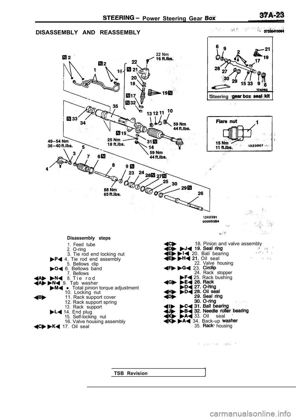
DISASSEMBLY AND REASSEMBLY
6
22 Nm
Steering
Disassembly steps
1.Feed tube2.O-ring3. Tie rod end locking nut
4. Tie rod end assembly5.Bellows clip 6. Bellows band7.Bellows8.T i e r o d 9. Tab washer l Total pinion torque adjustment
10. Locking nut
11. Rack support cover
12. Rack support spring
13.Rack support
14. End plug15.Self-locking nut16. Valve housing assembly
17. Oil seal 18. Pinion and valve assembly
20. Bali bearing 21.
Oil seal22.Valve housing
23. 24. Rack stopper 25. Rack bushing
33.Oil seal
34. Back-up 35. housing
TSB Revision
Page 1798 of 2103
S T E E R I N G Power Steering ,
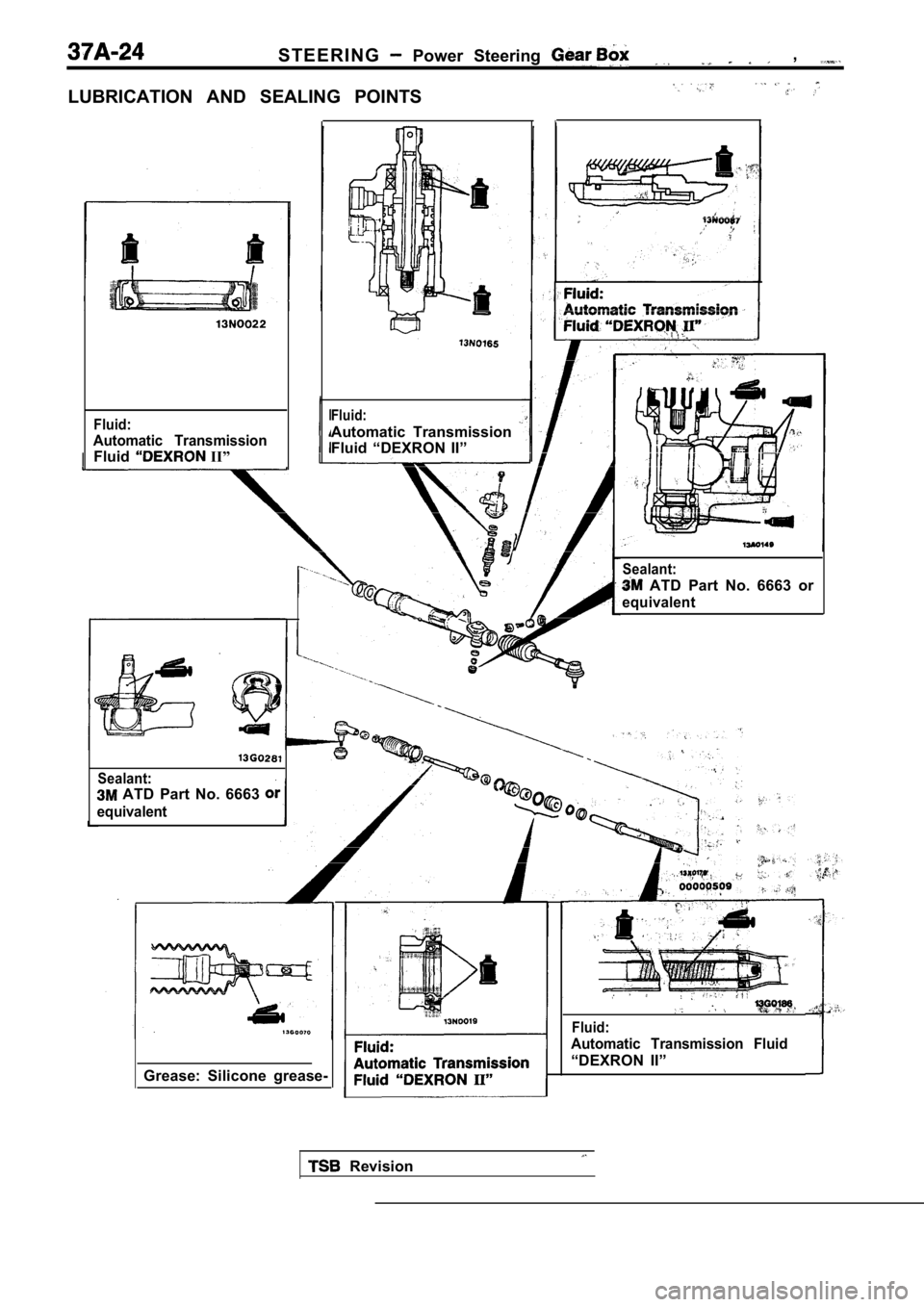
LUBRICATION AND SEALING POINTS
Fluid:
Automatic Transmission
Fluid II”
Grease: Silicone grease-
Fluid:
Automatic Transmission
Fluid “DEXRON II”
Sealant:
ATD Part No. 6663 or
equivalent
Sealant:
ATD Part No. 6663
equivalent
Fluid:
Automatic Transmission Fluid
“DEXRON II”
Revision
Page 1799 of 2103
STEERINGPower Gear ,
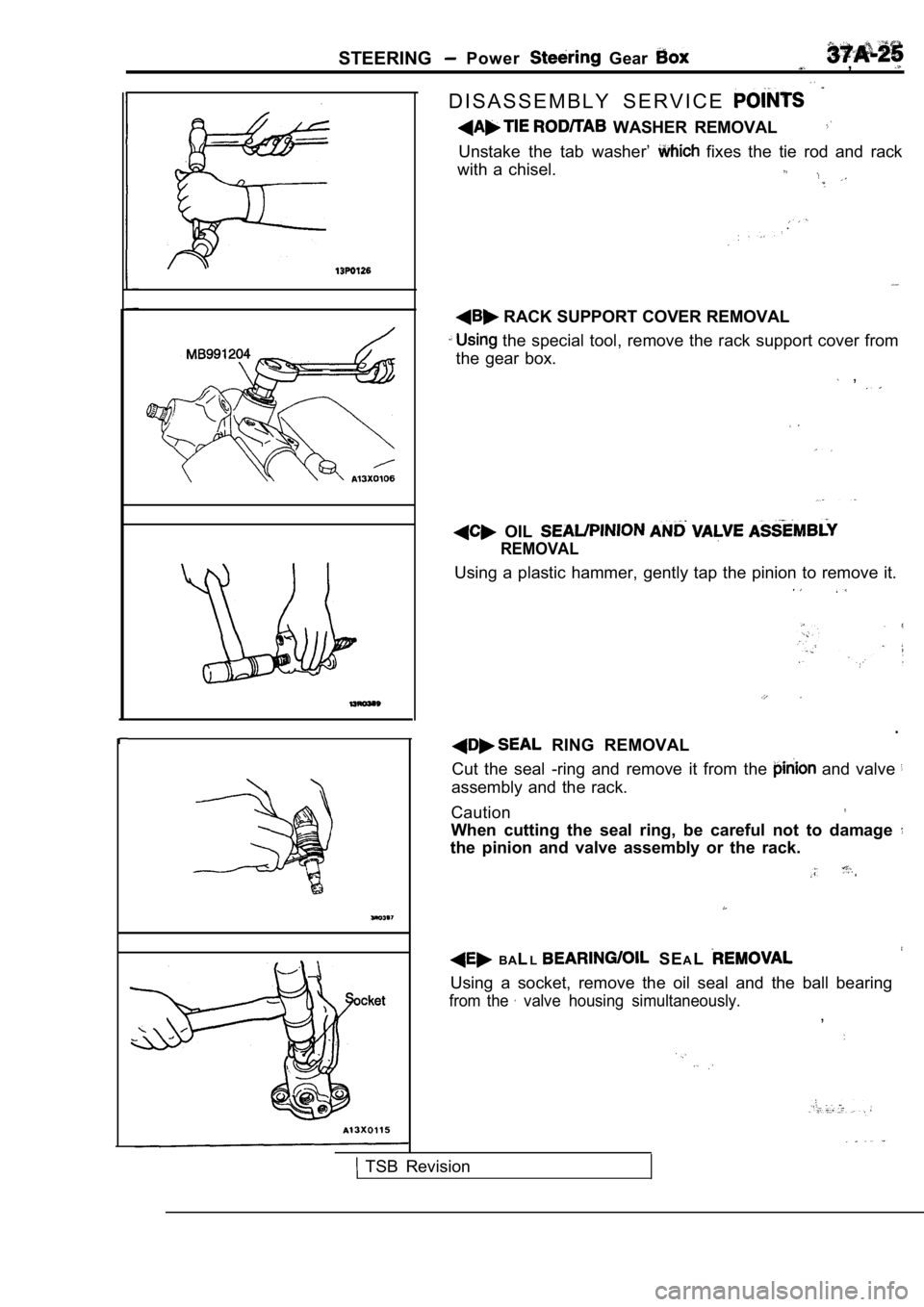
D I S A S S E M B L Y S E R V I C E
WASHER REMOVAL
Unstake the tab washer’ fixes the tie rod and rack
with a chisel.
RACK SUPPORT COVER REMOVAL
the special tool, remove the rack support cover fr om
the gear box.
,
OIL
REMOVAL
Using a plastic hammer, gently tap the pinion to re move it.
.
RING REMOVAL
Cut the seal -ring and remove it from the
and valve
assembly and the rack.
Caution
When cutting the seal ring, be careful not to damag e
the pinion and valve assembly or the rack.
BALL SE AL
Using a socket, remove the oil seal and the ball be aring
from the valve housing simultaneously.,
TSB Revision
Page 1800 of 2103
STEERING Power Steering Box
stopper
orbrass bar
Ball
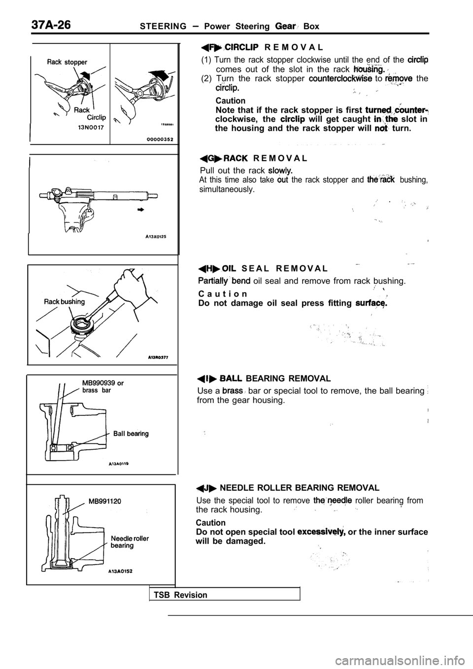
R E M O V A L
(1) Turn the rack stopper clockwise until the end of the
comes out of the slot in the rack
(2) Turn the rack stopper to the
Caution
Note that if the rack stopper is first
clockwise, the will get caught slot in
the housing and the rack stopper will
turn.
R E M O V A L
Pull out the rack
At this time also take the rack stopper and bushing,
simultaneously.
.
S E A L R E M O V A L
oil seal and remove from rack bushing.
C a u t i o n
Do not damage oil seal press fitting
BEARING REMOVAL
Use a
bar or special tool to remove, the ball bearing
from the gear housing.
TSB Revision
NEEDLE ROLLER BEARING REMOVAL
Use the special tool to remove roller bearing from
the rack housing.
Caution
Do not open special tool or the inner surface
will be damaged.