MITSUBISHI SPYDER 1990 Service Repair Manual
Manufacturer: MITSUBISHI, Model Year: 1990, Model line: SPYDER, Model: MITSUBISHI SPYDER 1990Pages: 2103, PDF Size: 68.98 MB
Page 1801 of 2103
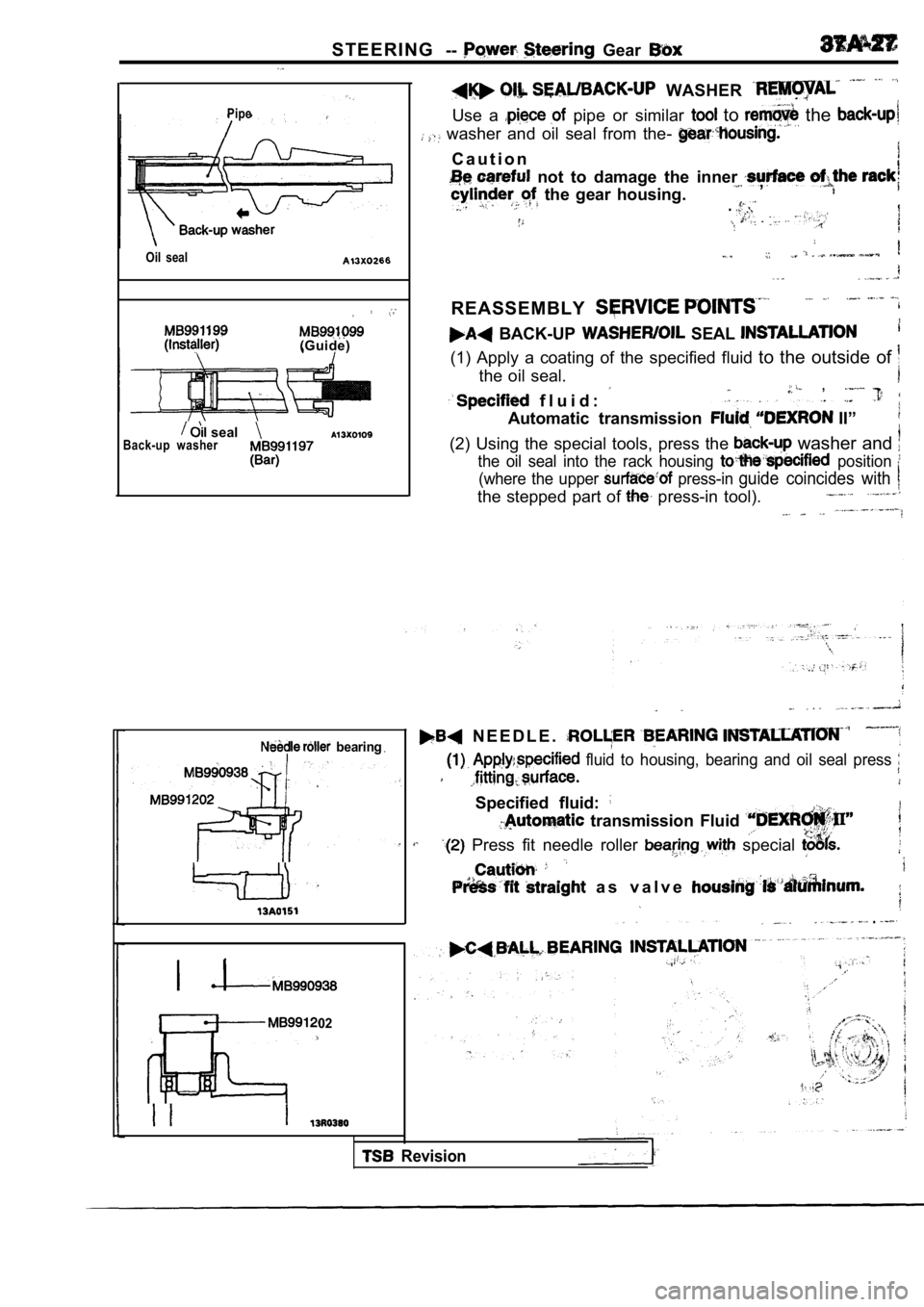
S T E E R I N G-- Gear
Pipe
Oil seal
(Guide)
sealBack-up washer
WASHER
Use a pipe or similar to the
washer and oil seal from the-
C a u t i o n
not to damage the inner , the gear housing..
REASSEMBLY
BACK-UP SEAL
(1) Apply a coating of the specified fluid to the outside of
the oil seal.
f l u i d :
,
Automatic transmission II”
(2) Using the special tools, press the washer and
the oil seal into the rack housing position
(where the upper press-in guide coincides with
the stepped part of press-in tool).
bearing
202
, N E E D L E .
fluid to housing, bearing and oil seal press
Specified fluid:
transmission Fluid
Press fit needle roller special
a s v a l v e
.
Revision
Page 1802 of 2103
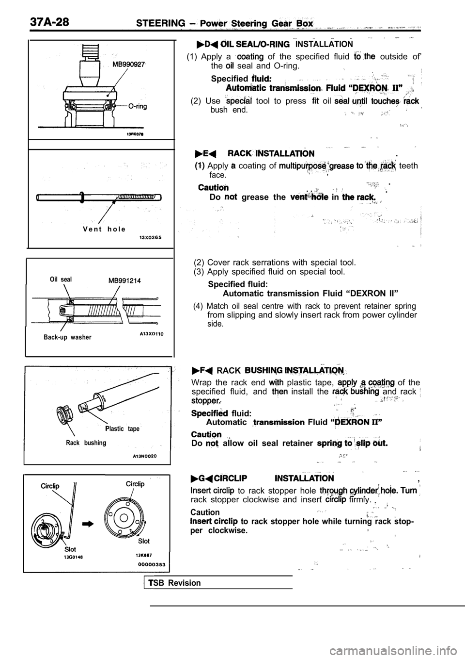
V e n t h o l e
Oil seal
Back-up washer
INSTALLATION
(1) Apply a of the specified fluid outside of’
the
seal and O-ring.
Specified
(2) Use tool to press oil
bush end.
.
Apply coating of teeth
face. ,
.. . .
Do grease the in
(2) Cover rack serrations with special tool.
(3) Apply specified fluid on special tool.
Specified fluid: Automatic transmission Fluid “DEXRON II”
(4) Match oil seal centre with rack to prevent reta iner spring
from slipping and slowly insert rack from power cylinder
side.
Plastic tape
Rack bushing
RACK
Wrap the rack end plastic tape, of the
specified fluid, and
install the and rack
fluid:
Automatic Fluid
Do allow oil seal retainer
,
to rack stopper hole
rack stopper clockwise and insert firmly.
Caution
to rack stopper hole while turning rack stop-
per clockwise.
,
TSB Revision
Page 1803 of 2103
S T E E R I N G P o w e r S t e e r i n g ,
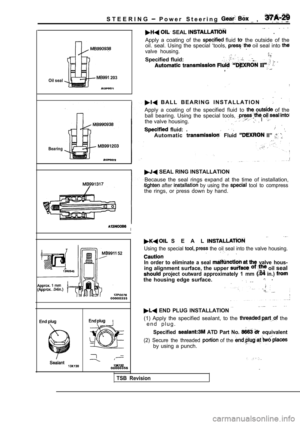
Oil seal 203
Bearing
52
. SEAL
Apply a coating of the fluid the outside of the
oil. seal. Using the special ‘tools,
oil seal into
valve housing..
Specified fluid:
,
B A L L B E A R I N G I N S T A L L A T I O N
Apply a coating of the specified fluid to of the
ball bearing. Using the special tools,
the valve housing.‘ I
fluid:
Automatic Fluid II” .
SEAL RING INSTALLATION
Because the seal rings expand at the time of instal lation,
after by using the tool to compress
the rings, or press down by hand.
I
S E A L
Using the special the oil seal into the valve housing.
In order to eliminate a seal valve hous-
ing alignment surface, the upper oil seal
project outward approximately 1 mm in.)
the housing edge surface. .
END PLUG INSTALLATION
(1) Apply the specified sealant, to the the
e n d p l u g .
Specified ATD Part No. equivalent
(2) Secure the threaded of the
by using a punch.
TSB Revision
Page 1804 of 2103
STEERING Power Steering Gear Box
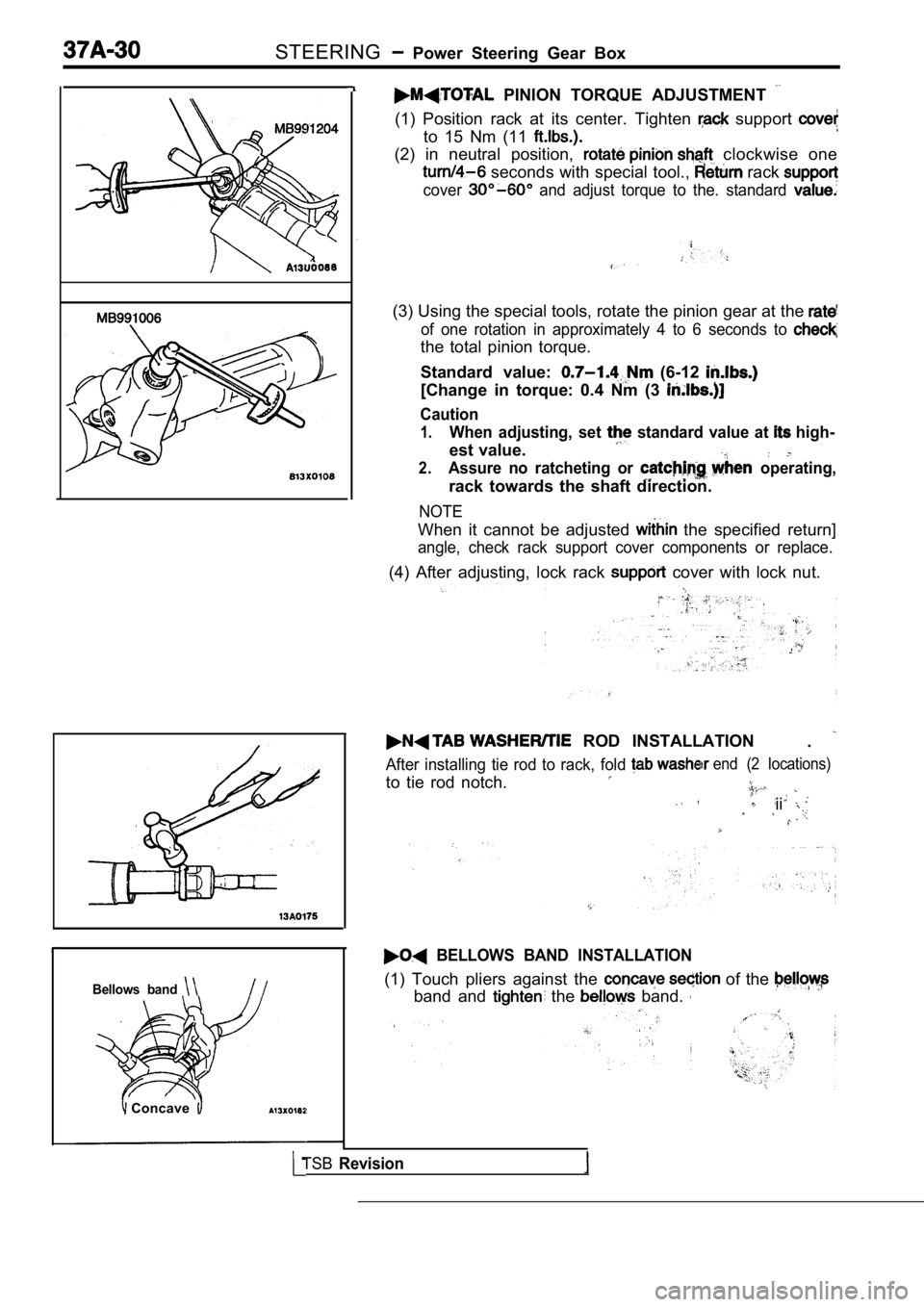
Bellows band
Concave
PINION TORQUE ADJUSTMENT
(1) Position rack at its center. Tighten support
to 15 Nm (11
(2) in neutral position, clockwise one
seconds with special tool., rack
cover and adjust torque to the. standard
(3) Using the special tools, rotate the pinion gear at the
of one rotation in approximately 4 to 6 seconds to
the total pinion torque.
Standard value:
(6-12
[Change in torque: 0.4 Nm (3
Caution
1.When adjusting, set standard value at high-
est value.
2.Assure no ratcheting or operating,
rack towards the shaft direction.
NOTE
When it cannot be adjusted the specified return]
angle, check rack support cover components or repla ce.
(4) After adjusting, lock rack cover with lock nut.
ROD INSTALLATION
.
After installing tie rod to rack, fold
to tie rod notch.
end (2 locations)
ii
BELLOWS BAND INSTALLATION
(1) Touch pliers against the of the
band and the band.
TSBRevision
Page 1805 of 2103
S T E E R I N G Steering
End of insertion groove
[Difference between theright and left tie rodend: or
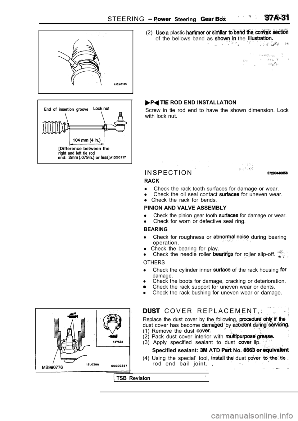
(2) plastic
of the bellows band as the
,
ROD END INSTALLATION
Screw in tie rod end to have the shown dimension. L ock
with lock nut.
I N S P E C T I O N
RACK
lCheck the rack tooth surfaces for damage or wear.
lCheck the oil seal contact for uneven wear.
l Check the rack for bends.
PINION AND VALVE ASSEMBLY
lCheck the pinion gear tooth for damage or wear.
lCheck for worn or defective seal ring.
BEARING
lCheck for roughness or during bearing
operation.
l Check the bearing for play.
lCheck the needle roller for roller slip-off.
OTHERS
lCheck the cylinder inner of the rack housing
damage.
lCheck the boots for damage, cracking or deteriorati on.
Check the rack support for uneven wear or dents.
lCheck the rack bushing for uneven wear or damage.
C O V E R R E P L A C E M E N T , :
Replace the dust cover by the following,
dust cover has become ‘by
(1) Remove the dust
(2) Pack dust cover interior with
(3) Apply specified sealant to dust lip.
Specified sealant: ATD No.
(4) Using the special’ tool, dust .
r o d e n d b a i l j o i n t . ,
TSB Revision
Page 1806 of 2103
STEERING Power Steering OilPump Engine,
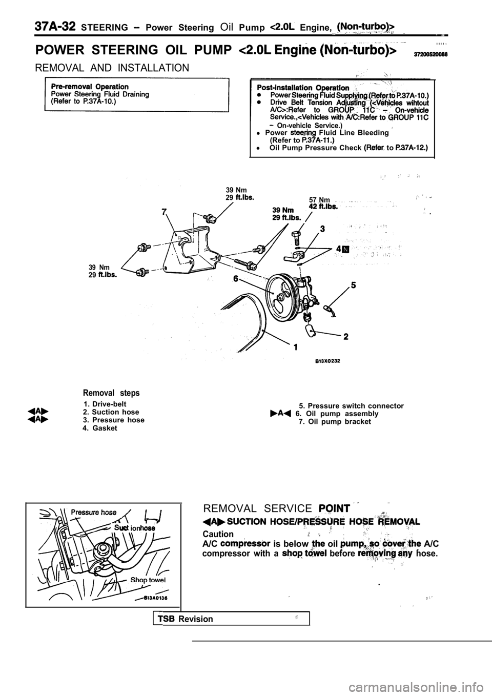
POWER STEERING OIL PUMP
. . . .
REMOVAL AND INSTALLATION
On-vehicle Service.)l Power Fluid Line Bleeding (Refer to l
Oil Pump Pressure Check to
39 Nm
29
57 Nm
.
39 Nm29
Removal steps
1. Drive-belt
2. Suction hose
3. Pressure hose
4. Gasket
uc ion ose
5. Pressure switch connector 6. Oil pump assembly 7. Oil pump bracket
REMOVAL SERVICE
Caution
A/C is below oil A/C
compressor with a before hose.
.
,
Revision
Page 1807 of 2103
STEERING Power Steering Oil Pump
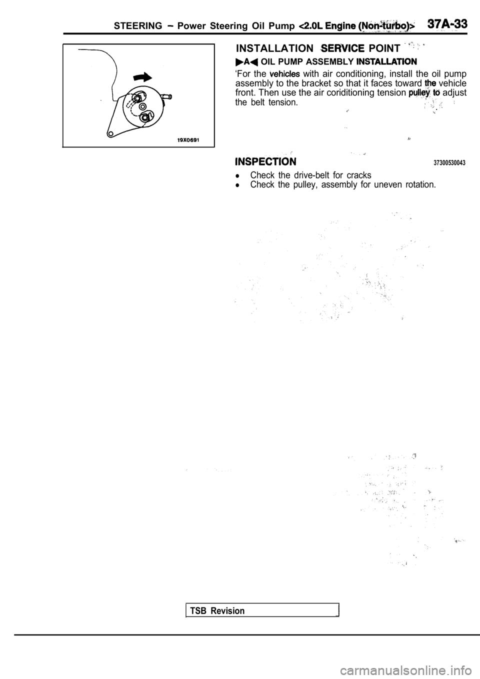
INSTALLATION POINT
OIL PUMP ASSEMBLY
‘For the with air conditioning, install the oil pump
assembly to the bracket so that it faces toward
vehicle
front. Then use the air coriditioning tension
adjust
the belt tension..
37300530043
�Check the drive-belt for cracks
�Check the pulley, assembly for uneven rotation.
TSB Revision
Page 1808 of 2103
STEERING Power Steering Pump Engine
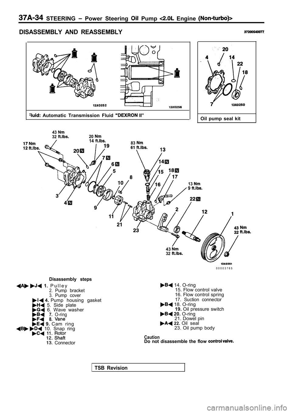
DISASSEMBLY AND REASSEMBLY
Automatic Transmission Fluid II”
4332201483
139
Oil pump seal kit
43
32
Disassembly steps
1. P u l l e y2.Pump bracket3.Pump cover
4. Pump housing gasket 5. Side plate 6. Wave washer7.O-ring8. 9. Cam ring 10. Snap ring
Connector
0 0 0 0 3 7 6 5
14. O-ring
15. Flow control valve
16. Flow control spring
17. Suction connector 18. O-ring 19. Oil pressure switch
20. O-ring
21. Dowel pin
22. Oil seal
23. Oil pump body
CautionDo not disassemble the flow
TSB Revision
Page 1809 of 2103
S T E E R I N G Power Steering Oil Pump Engine
9or
PressureportunionOilswitch
3
Rear pump housing,
Side plate
4
Suction port union
5 ’
TSB
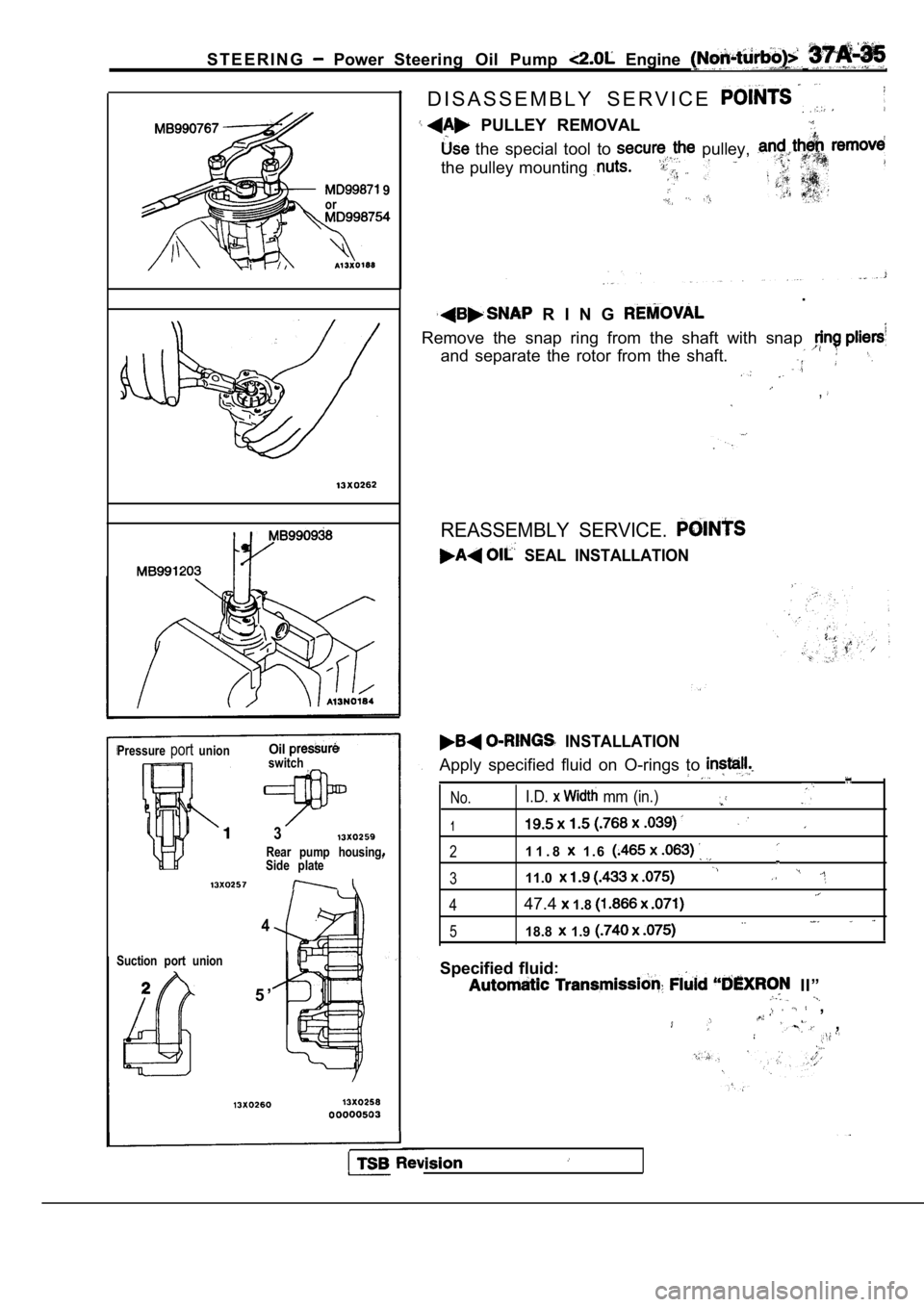
D I S A S S E M B L Y S E R V I C E
PULLEY REMOVAL
the special tool to pulley,
the pulley mounting
.
R I N G
Remove the snap ring from the shaft with snap
and separate the rotor from the shaft.
,
REASSEMBLY SERVICE.
SEAL INSTALLATION
INSTALLATION
Apply specified fluid on O-rings to
No.I.D. mm (in.)
1
21 1 . 8 1 . 6
311.0
447.4 1.8
518.8 1.9
Specified fluid:
II”
,
,
Page 1810 of 2103
STEERING Power Steering Oil Pump Engine (Non-turbo)>
Punch mark
Snap ring
Direct round edgeto the cam rina
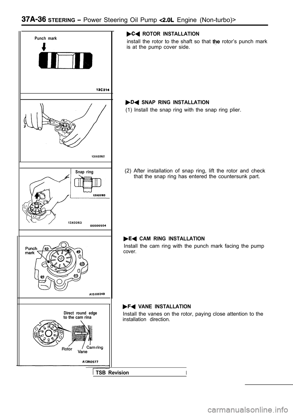
ROTOR INSTALLATION
install the rotor to the shaft so that rotor’s punch mark
is at the pump cover side.
SNAP RING INSTALLATION
(1) Install the snap ring with the snap ring plier.
(2) After installation of snap ring, lift the rotor and check
that the snap ring has entered the countersunk part .
CAM RING INSTALLATION
Install the cam ring with the punch mark facing the pump
cover.
VANE INSTALLATION
Install the vanes on the rotor, paying close attention to the
installation direction.
TSB RevisionI