MITSUBISHI SPYDER 1990 Service Repair Manual
Manufacturer: MITSUBISHI, Model Year: 1990, Model line: SPYDER, Model: MITSUBISHI SPYDER 1990Pages: 2103, PDF Size: 68.98 MB
Page 1901 of 2103
B O D Y Entry System
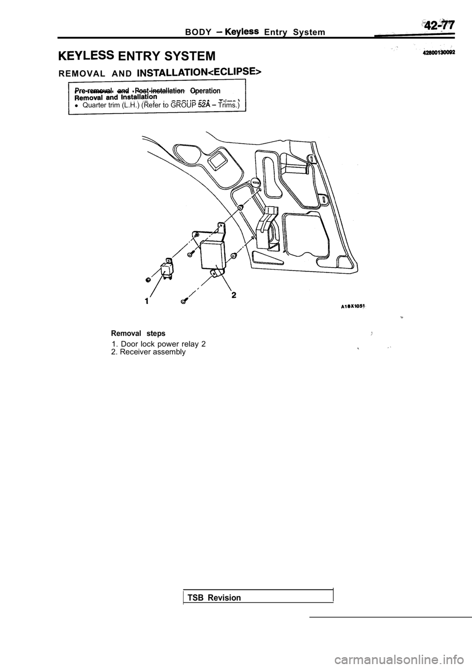
ENTRY SYSTEM
R E M O V A L A N D
Pre-removal and Post-installation Operation
l Quarter trim (L.H.) (Refer to GROUP Trims.)
Removal steps
1. Door lock power relay 2
2. Receiver assembly
TSB Revision
Page 1902 of 2103
B O D Y Entry System
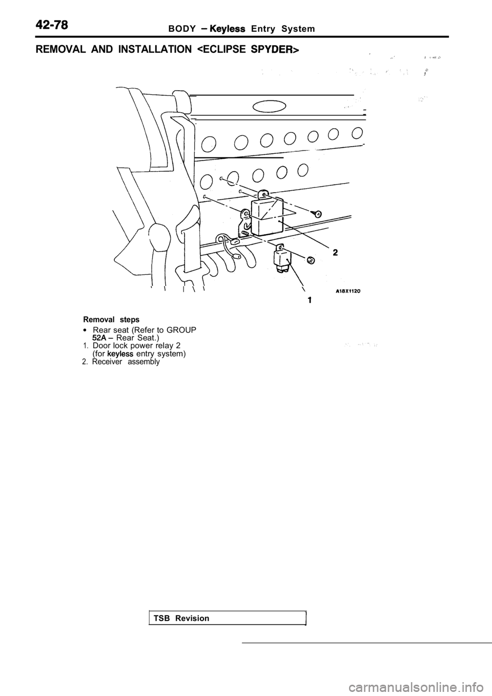
REMOVAL AND INSTALLATION
Removal steps
l
1.
2.
Rear seat (Refer to GROUP Rear Seat.)
Door lock power relay 2
(for
entry system)Receiver assembly
TSB Revision
Page 1903 of 2103
BODY Entry System
Battery
INSPECTION
DOOR LOCK POWER RELAY 2 CHECK
Refer to
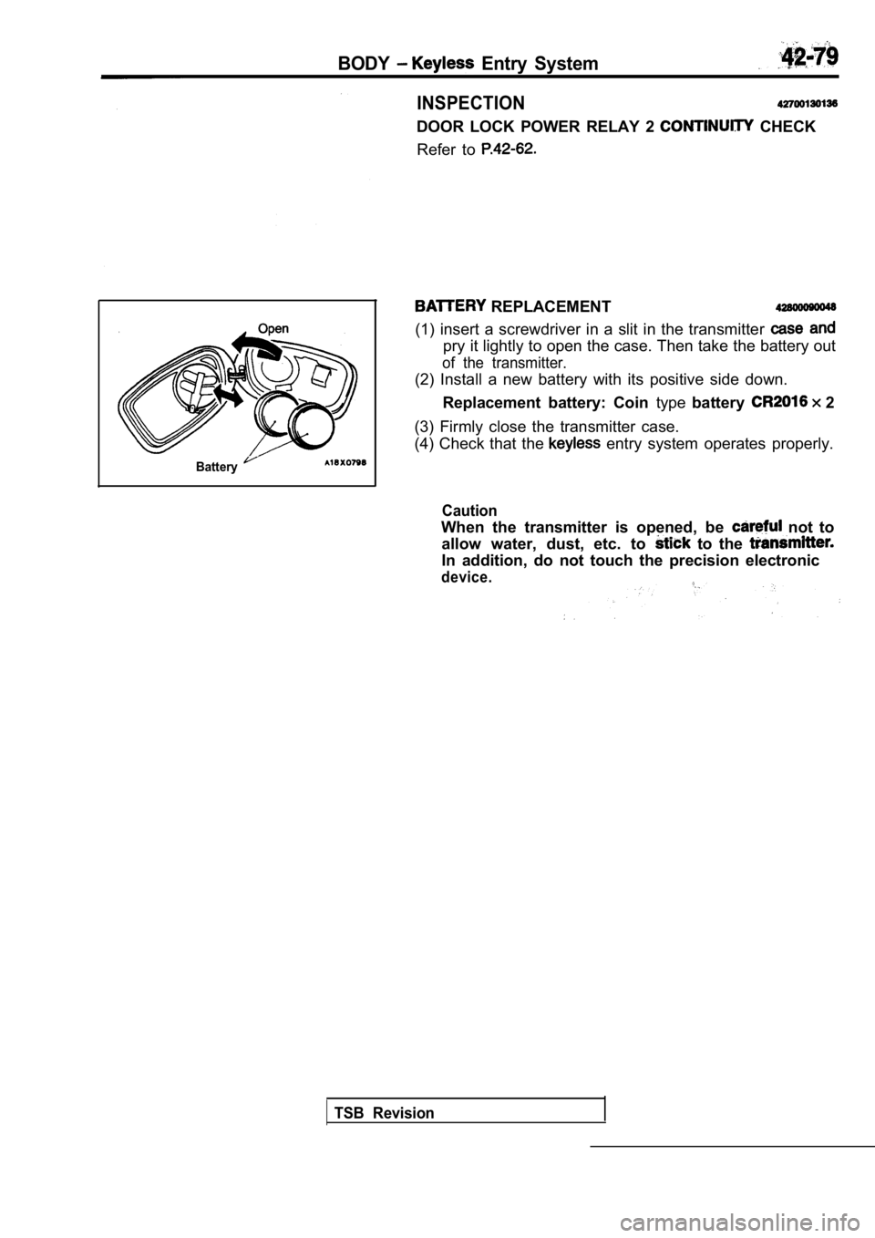
REPLACEMENT
(1) insert a screwdriver in a slit in the transmitt er
pry it lightly to open the case. Then take the batt ery out
of the transmitter.
(2) Install a new battery with its positive side do wn.
Replacement battery: Coin typebattery
2
(3) Firmly close the transmitter case.
(4) Check that the
entry system operates properly.
Caution
When the transmitter is opened, be not to
allow water, dust, etc. to
to the
In addition, do not touch the precision electronic
device.
TSB Revision
Page 1904 of 2103
Entry System
METHOD OF REGISTERING A SECRET CODE
Each individual secret code is registered inside the transmitter,
and so it is necessary to register these codes with the received
in the following cases.
lWhen either the transmitter or receiver is replaced;
lIf a second transmitter is to be used;
lIf it appears that a problem is occurring because o f faulty
registration of a code.
A maximum of two different codes per transmitter ca n be
stored in the memory area of the EEPROM, and up to two
different transmitters can be used. When the codes for the
first transmitter are registered, the previously-registered codes
for both transmitters are cleared. Therefore, if yo u are using
two transmitters or are adding a second transmitter , the
for both transmitters must be the same time.
(1) Check that the door locking function works norm ally using
the door key.
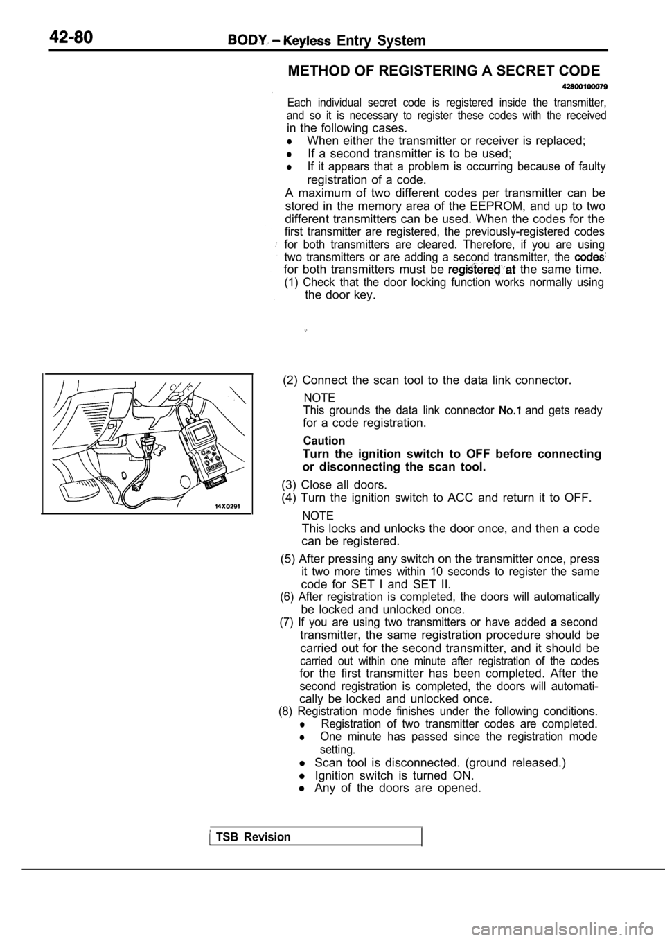
(2) Connect the scan tool to the data link connecto r.
NOTE
This grounds the data link connector
and gets ready
for a code registration.
Caution
Turn the ignition switch to OFF before connecting
or disconnecting the scan tool.
(3) Close all doors.
(4) Turn the ignition switch to ACC and return it t o OFF.
NOTE
This locks and unlocks the door once, and then a co de
can be registered.
(5) After pressing any switch on the transmitter on ce, press
it two more times within 10 seconds to register the same
code for SET I and SET II.
(6) After registration is completed, the doors will automatically
be locked and unlocked once.
(7) If you are using two transmitters or have added asecond
transmitter, the same registration procedure should be
carried out for the second transmitter, and it shou ld be
carried out within one minute after registration of the codes
for the first transmitter has been completed. After the
second registration is completed, the doors will au tomati-
cally be locked and unlocked once.
(8) Registration mode finishes under the following conditions.
lRegistration of two transmitter codes are completed .
lOne minute has passed since the registration mode
setting.
l Scan tool is disconnected. (ground released.)
l Ignition switch is turned ON.
l Any of the doors are opened.
TSB Revision
Page 1905 of 2103
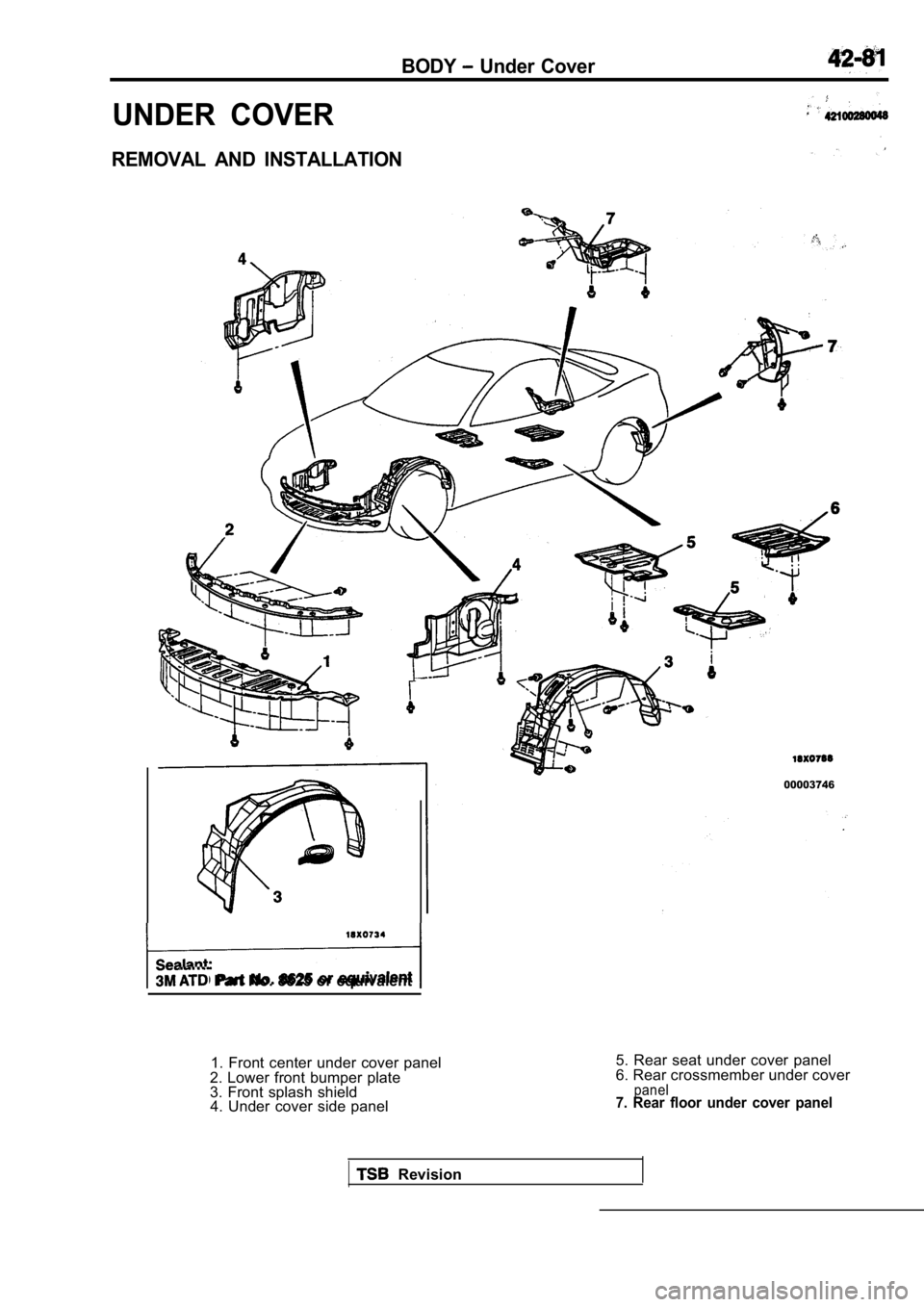
BODY Under Cover
UNDER COVER
REMOVAL AND INSTALLATION
Part No. 8825 or equivalent
00003746
1. Front center under cover panel
2. Lower front bumper plate
3. Front splash shield 4. Under cover side panel 5. Rear seat under cover panel
6. Rear crossmember under cover
panel7. Rear floor under cover panel
Revision
Page 1906 of 2103
42-82BODY Sunroof
SUNROOF
GENERAL
A motor-driven outer slide-type glass sunroof with
a tilt-up mechanism is provided as an option fora sufficient amount of lighting and a feeling of
all models. Even when the sunroof is fully closed,
openness can still be obtained by opening the
sunroof sunshade.
SEALANT AND ADHESIVE
Items
Sunroof glass attaching screws
Sunroof glass sealing Specified sealant and adhesive
Loctite Small Screw Threadlocker 222 or equivalent
410 Black Toughened Instant Adhesive or
equivalent
in.)
Hose
ON-VEHICLE SERVICE
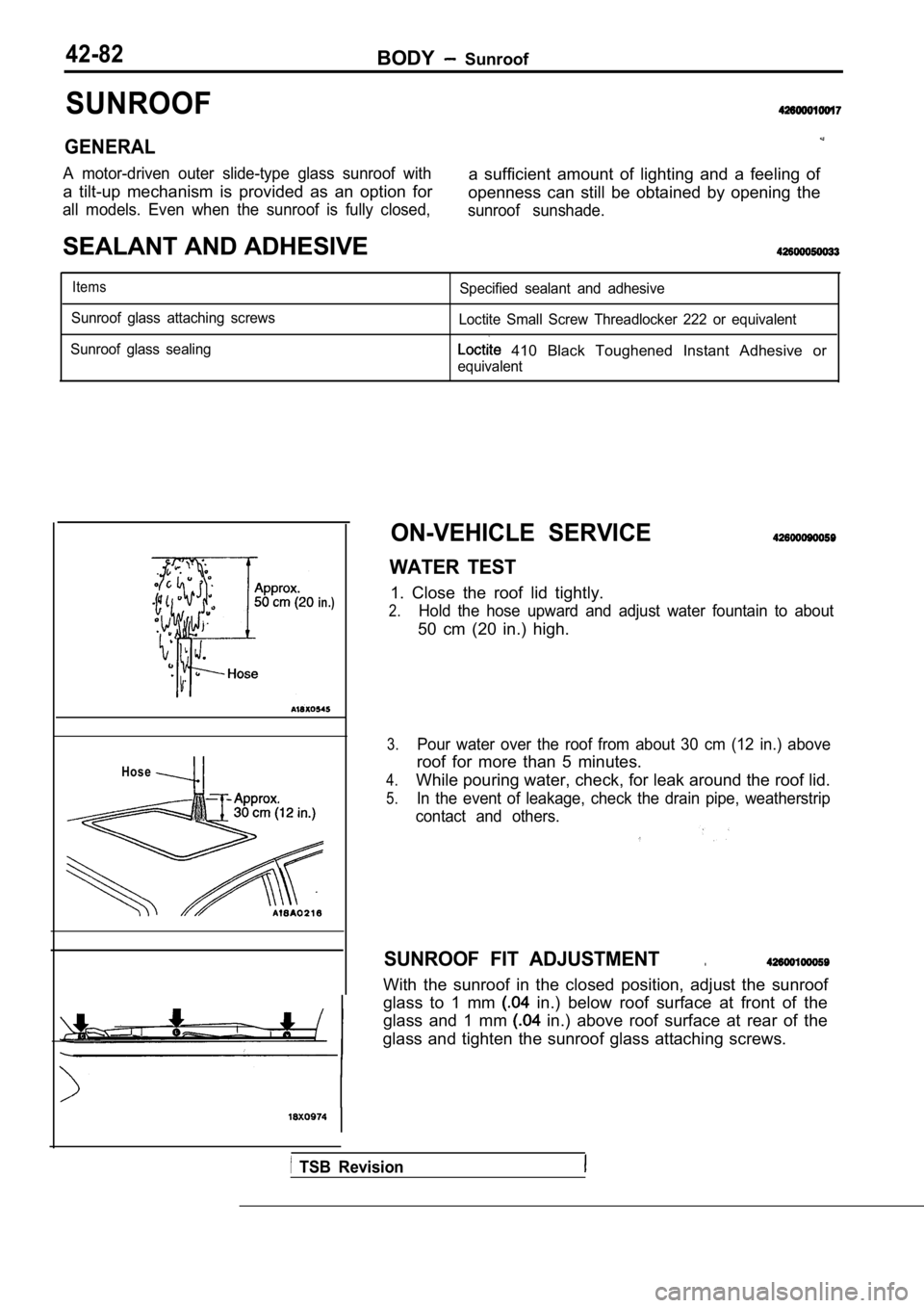
WATER TEST
1. Close the roof lid tightly.
2.Hold the hose upward and adjust water fountain to a bout
50 cm (20 in.) high.
3.Pour water over the roof from about 30 cm (12 in.) above
roof for more than 5 minutes.
4.While pouring water, check, for leak around the roof lid.
5.In the event of leakage, check the drain pipe, weatherstrip
contact and others.
SUNROOF FIT ADJUSTMENT.
With the sunroof in the closed position, adjust the sunroof
glass to 1 mm
in.) below roof surface at front of the
glass and 1 mm
in.) above roof surface at rear of the
glass and tighten the sunroof glass attaching screw s.
TSB Revision
Page 1907 of 2103
BODY Sunroof
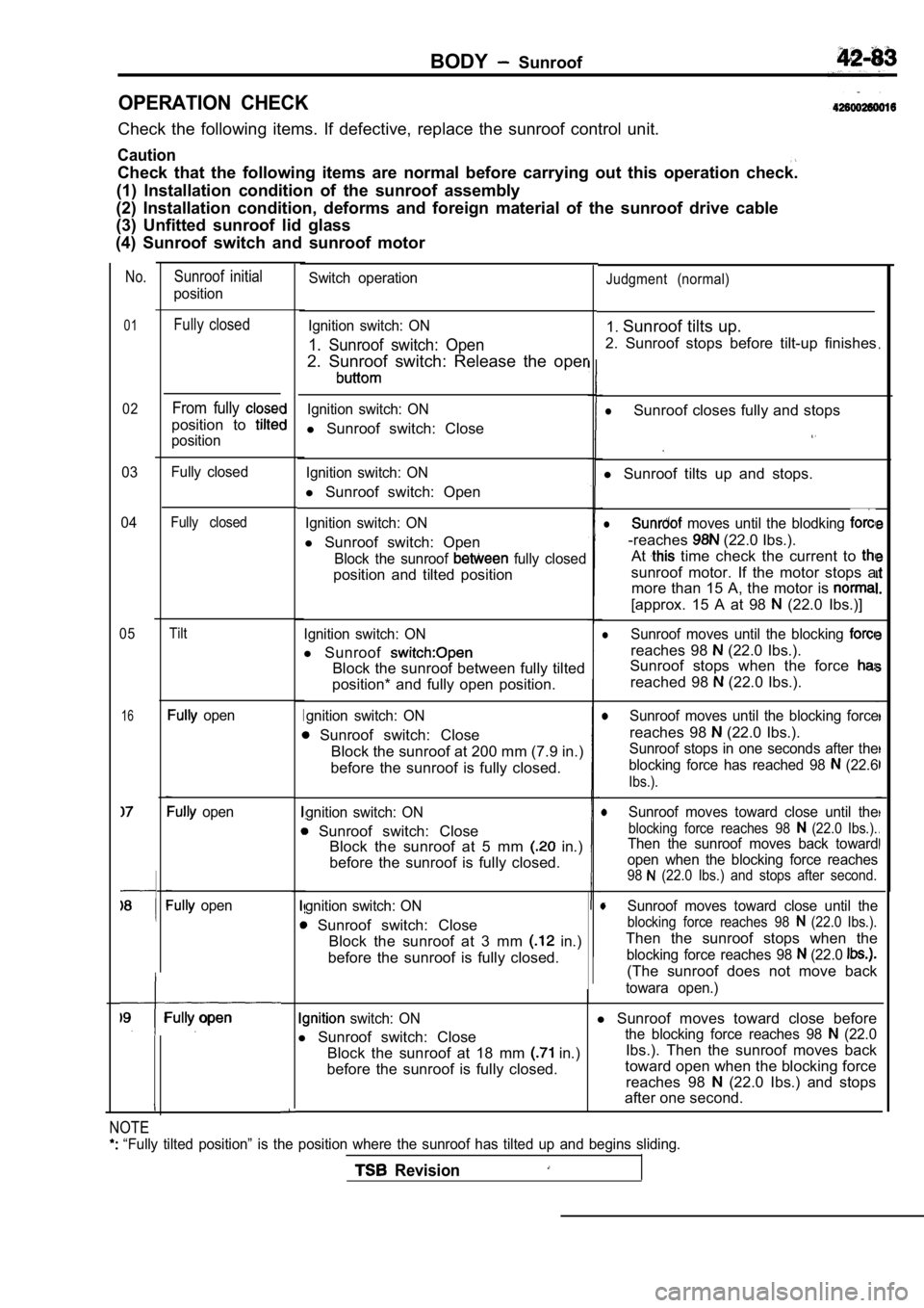
OPERATION CHECK
Check the following items. If defective, replace the sunroof control unit.
Caution
Check that the following items are normal before ca rrying out this operation check.
(1) Installation condition of the sunroof assembly
(2) Installation condition, deforms and foreign mat erial of the sunroof drive cable
(3) Unfitted sunroof lid glass
(4) Sunroof switch and sunroof motor
No.
01
02
03
04
05
16
Sunroof initial
position
Fully closed
From fully
position to
position
Fully closed
Fully closed
Tilt
open
open
open
Fully open
Ignition switch: ON
l Sunroof switch: Close
lSunroof closes fully and stops
Ignition switch: ON
l Sunroof switch: Open l
Sunroof tilts up and stops.
Ignition switch: ON
l Sunroof switch: Open
Block the sunroof fully closed
position and tilted position
l moves until the blodking
-reaches (22.0 Ibs.).
At
time check the current to
sunroof motor. If the motor stops a more than 15 A, the motor is
[approx. 15 A at 98 (22.0 Ibs.)]
Ignition switch: ON
l Sunroof
Block the sunroof between fully tilted
position* and fully open position.
lSunroof moves until the blocking
reaches 98 (22.0 Ibs.).
Sunroof stops when the force
reached 98 (22.0 Ibs.).
gnition switch: ON
Sunroof switch: Close
Block the sunroof at 200 mm (7.9 in.)
before the sunroof is fully closed.
ISunroof moves until the blocking force
reaches 98 (22.0 Ibs.).
gnition switch: ON
Sunroof switch: Close Block the sunroof at 5 mm in.)
before the sunroof is fully closed.
Sunroof stops in one seconds after the
blocking force has reached 98
(22.6
Ibs.).
Sunroof moves toward close until the
blocking force reaches 98 (22.0 Ibs.).Then the sunroof moves back toward
open when the blocking force reaches
98 (22.0 Ibs.) and stops after second.
gnition switch: ON
Sunroof switch: Close Block the sunroof at 3 mm
in.)
before the sunroof is fully closed.
Sunroof moves toward close until the
blocking force reaches 98 (22.0 Ibs.).
Then the sunroof stops when the
blocking force reaches 98 (22.0
(The sunroof does not move back
towara open.)
switch: ONl Sunroof moves toward close before
l Sunroof switch: Close
the blocking force reaches 98 (22.0
Block the sunroof at 18 mm in.) Ibs.). Then the sunroof moves back
before the sunroof is fully closed. toward open when the blocking force
reaches 98
(22.0 Ibs.) and stops
after one second.
Switch operationJudgment (normal)
Ignition switch: ON
1. Sunroof switch: Open
2. Sunroof switch: Release the oper
1. Sunroof tilts up.
2. Sunroof stops before tilt-up finishes
.
NOTE
“Fully tilted position” is the position where the sunroof has tilted up and begins sliding.
Revision
Page 1908 of 2103

42-84BODY Sunroof
No.Sunroof initial
position Switch operation
Judgment (normal)
10Fully open
11Fully closedIgnition switch: ON
lSunroof moves toward close until
l
Sunroof switch: Closeblocking force reaches 98 (22.0
Block the sunroof at 16 mm in.) Then the sunroof stops when
before the sunroof is fully closed.blocking force reaehes 98 (22.0
(The sunroof does not ‘move back
toward. .
Ignition switch: ON1. Sunroof tilts up.
1. Sunroof switch: Open 2. Sunroof stops before tilt-up finishes.
2. Sunroof switch: Release the open
12Tilt up Ignition switch: ON
1. Sunroof switch: Open
2. Ignition switch: OFF
(before the sunroof is fully open) 1. Sunroof moves toward open.
2. Sunroof stops.
13Fully openIgnition switch: ON
1. Sunroof switch: Close
2. Ignition switch: OFF
(before tilt-up finishes) 1. Sunroof tilts up.
2. Sunroof stops
14 up Ignition switch: ONlSunroof moves toward close until the
l Sunroof switch: Open
blocking force reaches 98 (22.0 Ibs.).
Block the sunroof between fully tilted Then the sunroof stops when the
position and fully open position.blocking force reaches 98 (22.0 Ibs.).
TSB Revision
Page 1909 of 2103
B O D Y,
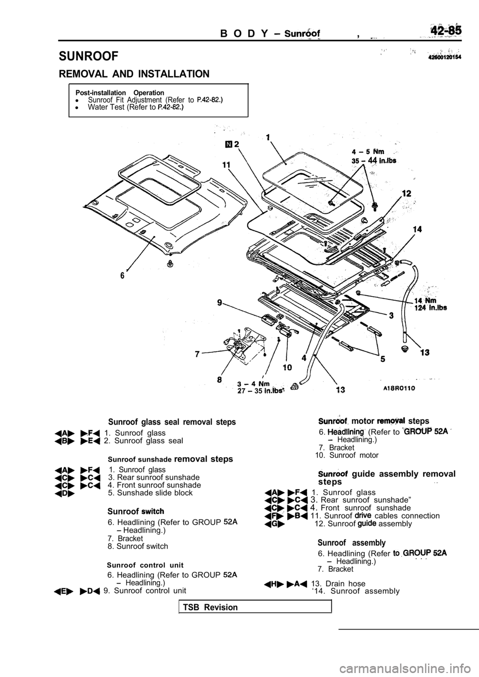
SUNROOF
REMOVAL AND INSTALLATION
Post-installation OperationlSunroof Fit Adjustment (Refer to lWater Test (Refer to
44 44
66
27 35
Sunroof glass seal removal steps
1. Sunroof glass 2. Sunroof glass sealSunroof sunshade removal steps
1. Sunroof glass3. Rear sunroof sunshade
4. Front sunroof sunshade 5. Sunshade slide block
motor steps
6. (Refer to Headlining.)
7. Bracket
10. Sunroof motor
Sunroof
6. Headlining (Refer to GROUP Headlining.)
guide assembly removal
steps
1. Sunroof glass 3. Rear sunroof sunshade” 4. Front sunroof sunshade 11. Sunroof cables connection
12. Sunroof assembly
7. Bracket8. Sunroof switch
Sunroof control unitSunroof assembly
6. Headlining (Refer Headlining.)
7. Bracket. .
6. Headlining (Refer to GROUP Headlining.) 9. Sunroof control unit 13. Drain hose ‘14. Sunroof assembly
TSB Revision
Page 1910 of 2103
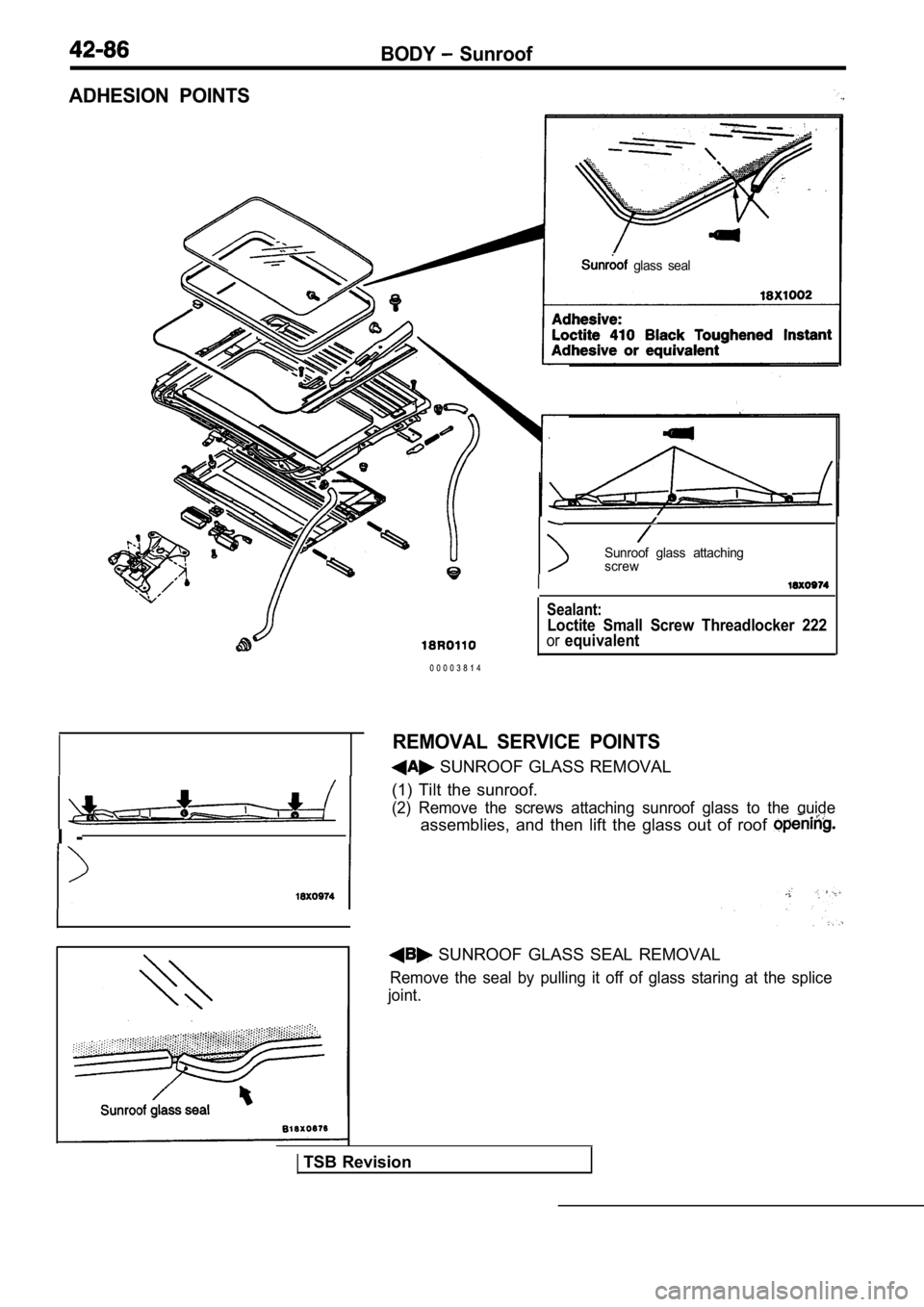
BODY Sunroof
ADHESION POINTS
glass seal
I -i
Sunroof glass attaching
screw
I
0 0 0 0 3 8 1 4
Sealant:
Loctite Small Screw Threadlocker 222orequivalent
REMOVAL SERVICE POINTS
SUNROOF GLASS REMOVAL
(1) Tilt the sunroof.
(2) Remove the screws attaching sunroof glass to th e guide
assemblies, and then lift the glass out of roof
SUNROOF GLASS SEAL REMOVAL
Remove the seal by pulling it off of glass staring at the splice
joint.
TSB Revision