MITSUBISHI SPYDER 1990 Service Repair Manual
Manufacturer: MITSUBISHI, Model Year: 1990, Model line: SPYDER, Model: MITSUBISHI SPYDER 1990Pages: 2103, PDF Size: 68.98 MB
Page 1911 of 2103
B O D Y ,
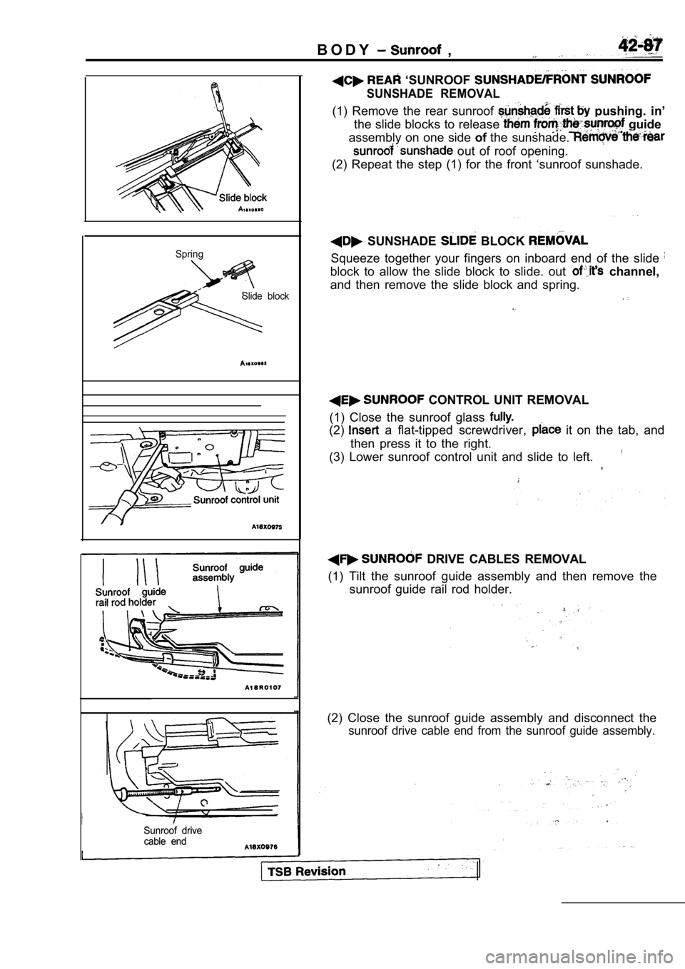
SpringSlide block
Sunroof drive
Sunroof drive
cable end
cable end
‘SUNROOF
SUNSHADE REMOVAL
(1) Remove the rear sunroof pushing. in’
the slide blocks to release
guide
assembly on one side ofthe sunshade.
out of roof opening.
(2) Repeat the step (1) for the front ‘sunroof suns hade.
SUNSHADE BLOCK
Squeeze together your fingers on inboard end of the slide
block to allow the slide block to slide. out channel,
and then remove the slide block and spring.
CONTROL UNIT REMOVAL
(1) Close the sunroof glass
(2) a flat-tipped screwdriver, it on the tab, and
then press it to the right.
(3) Lower sunroof control unit and slide to left.
,
DRIVE CABLES REMOVAL
(1) Tilt the sunroof guide assembly and then remove the
sunroof guide rail rod holder.
(2) Close the sunroof guide assembly and disconnect the
sunroof drive cable end from the sunroof guide assembly.
Page 1912 of 2103
42-88BODY Sunroof
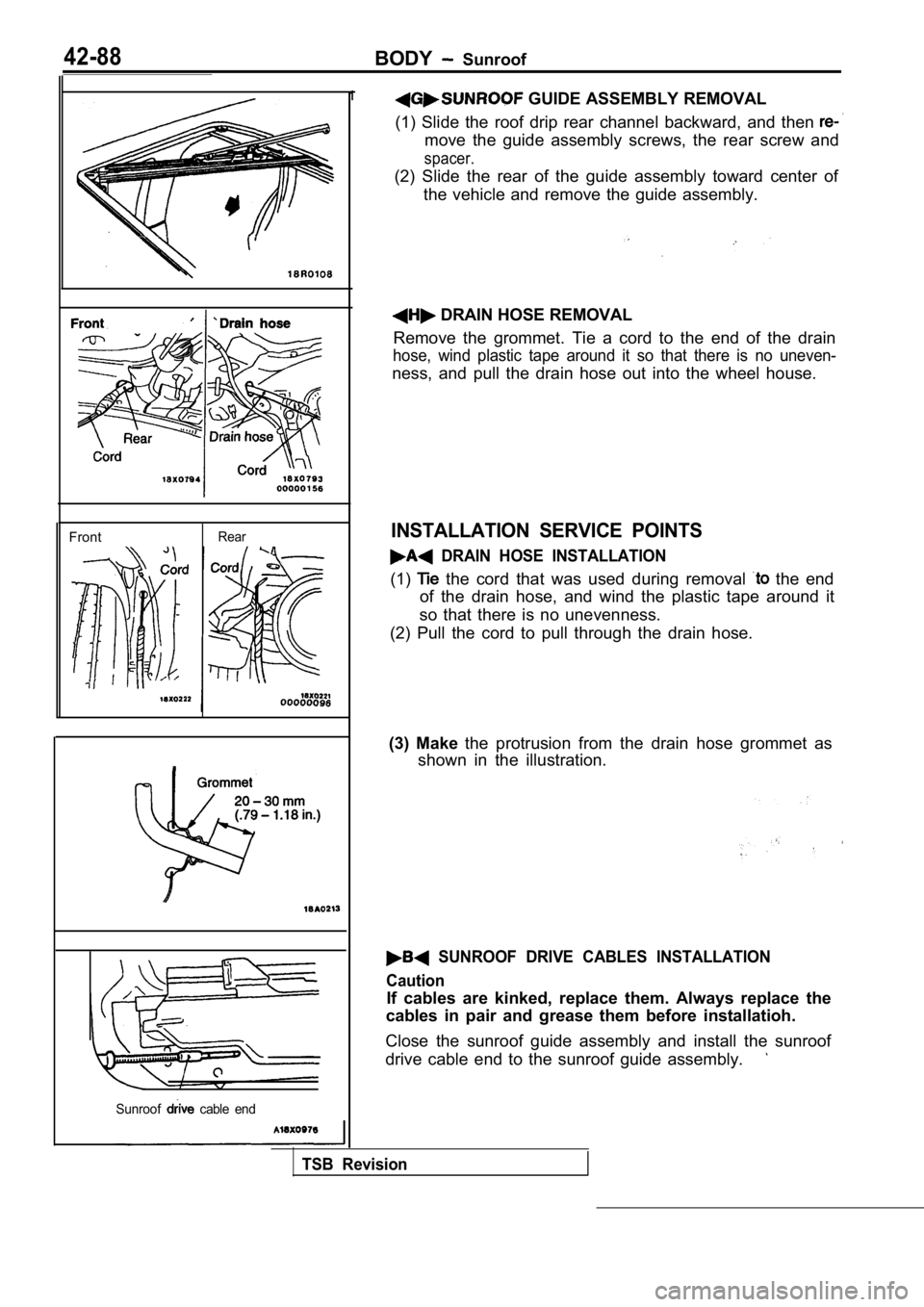
Front
Rear
Sunroof
cable end
1 GUIDE ASSEMBLY REMOVAL
(1) Slide the roof drip rear channel backward, and then
move the guide assembly screws, the rear screw and
spacer.
(2) Slide the rear of the guide assembly toward cen ter of
the vehicle and remove the guide assembly.
DRAIN HOSE REMOVAL
Remove the grommet. Tie a cord to the end of the dr ain
hose, wind plastic tape around it so that there is no uneven-
ness, and pull the drain hose out into the wheel ho use.
INSTALLATION SERVICE POINTS
DRAIN HOSE INSTALLATION
(1) the cord that was used during removal the end
of the drain hose, and wind the plastic tape around it
so that there is no unevenness.
(2) Pull the cord to pull through the drain hose.
(3) Make the protrusion from the drain hose grommet as
shown in the illustration.
SUNROOF DRIVE CABLES INSTALLATION
Caution
If cables are kinked, replace them. Always replace the
cables in pair and grease them before installatioh.
Close the sunroof guide assembly and install the su nroof
drive cable end to the sunroof guide assembly.
TSB Revision
Page 1913 of 2103
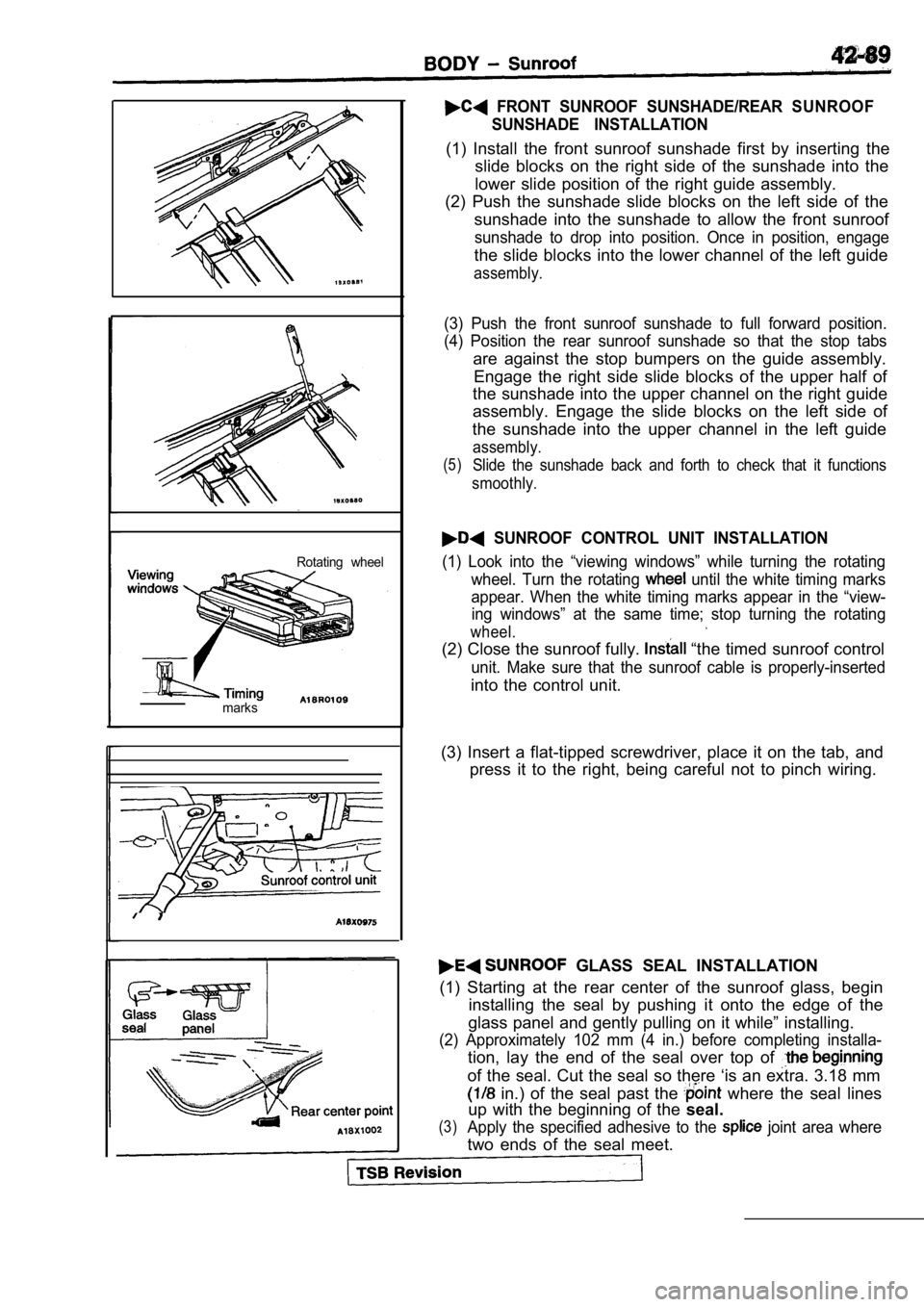
Rotating wheel
marks
FRONT SUNROOF SUNSHADE/REAR SUNROOF SUNSHADE INSTALLATION
(1) Install the front sunroof sunshade first by ins erting the
slide blocks on the right side of the sunshade into the
lower slide position of the right guide assembly.
(2) Push the sunshade slide blocks on the left side of the
sunshade into the sunshade to allow the front sunro of
sunshade to drop into position. Once in position, engage
the slide blocks into the lower channel of the left guide
assembly.
(3) Push the front sunroof sunshade to full forward position.
(4) Position the rear sunroof sunshade so that the stop tabs
are against the stop bumpers on the guide assembly.
Engage the right side slide blocks of the upper hal f of
the sunshade into the upper channel on the right gu ide
assembly. Engage the slide blocks on the left side of
the sunshade into the upper channel in the left gui de
assembly.
(5)Slide the sunshade back and forth to check that it functions
smoothly.
SUNROOF CONTROL UNIT INSTALLATION
(1) Look into the “viewing windows” while turning t he rotating
wheel. Turn the rotating
until the white timing marks
appear. When the white timing marks appear in the “ view-
ing windows” at the same time; stop turning the rot ating
wheel.
(2) Close the sunroof fully. “the timed sunroof control
unit. Make sure that the sunroof cable is properly-inserted
into the control unit.
(3) Insert a flat-tipped screwdriver, place it on t he tab, and
press it to the right, being careful not to pinch w iring.
GLASS SEAL INSTALLATION
(1) Starting at the rear center of the sunroof glas s, begin
installing the seal by pushing it onto the edge of the
glass panel and gently pulling on it while” install ing.
(2) Approximately 102 mm (4 in.) before completing installa-
tion, lay the end of the seal over top of
of the seal. Cut the seal so there ‘is an extra. 3.18 mm
in.) of the seal past the where the seal lines
up with the beginning of the seal.
(3)Apply the specified adhesive to the joint area where
two ends of the seal meet.
Page 1914 of 2103
BODY Sunroof
Specified adhesive:Loctite 410 Black Toughened Instant Adhesive or
equivalent. .
(4) With the approximately 102 mm (4 the seal unat-
tached, push two ends of the seal together at glue joint.
(5) Install remainder of the seal by pushing onto
the edge of the glass panel. The 3.18 mm of extra
seal material should strengthen the seal at the splice
joint.
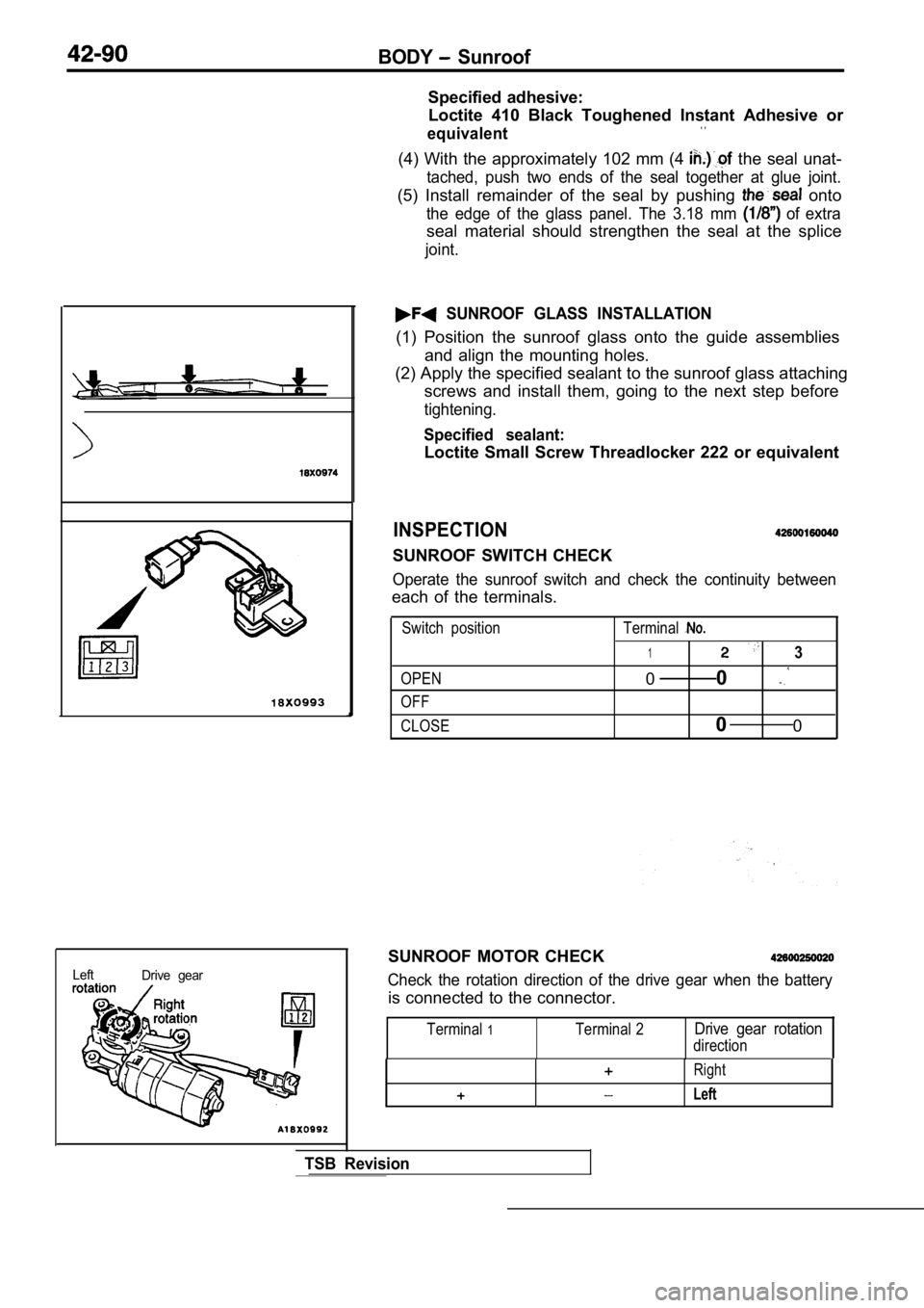
Left
Drive gear
SUNROOF GLASS INSTALLATION
(1) Position the sunroof glass onto the guide assem blies
and align the mounting holes.
(2) Apply the specified sealant to the sunroof glas s attaching
screws and install them, going to the next step bef ore
tightening.
Specified sealant:
Loctite Small Screw Threadlocker 222 or equivalent
INSPECTION
SUNROOF SWITCH CHECK
Operate the sunroof switch and check the continuity between
each of the terminals.
Switch position
OPEN
OFF Terminal
13
0
0
CLOSE0
0
SUNROOF MOTOR CHECK
Check the rotation direction of the drive gear when the battery
is connected to the connector.
Terminal1Terminal 2Drive gear rotation
direction
TSB Revision
Right
Left
Page 1915 of 2103
BODY Convertible Top
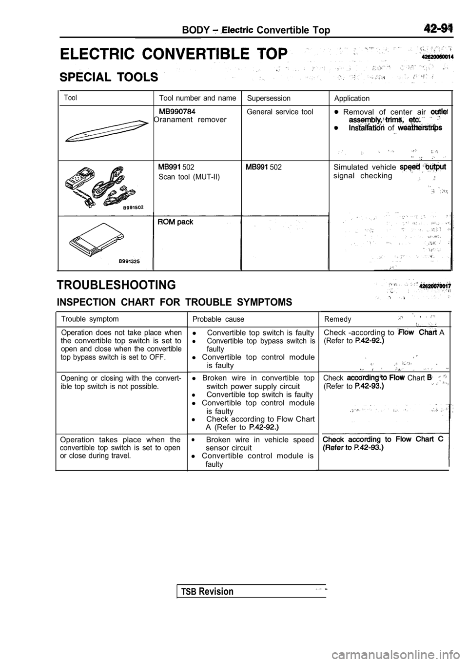
ToolTool number and nameSupersessionApplication
General service tool Removal of center air Oranament remover
of
502
Scan tool (MUT-II) 502Simulated vehicle
signal checking
TROUBLESHOOTING
INSPECTION CHART FOR TROUBLE SYMPTOMS
Trouble symptom
Operation does not take place when
the convertible top switch is set to
open and close when the convertible
top bypass switch is set to OFF.
Opening or closing with the convert- ible top switch is not possible.
Operation takes place when the
convertible top switch is set to openor close during travel. Probable cause
l
Convertible top switch is faulty
lConvertible top bypass switch is
faulty
l Convertible top control module
is faulty
l Broken wire in convertible top
switch power supply circuit
lConvertible top switch is faulty
l Convertible top control module
is faulty
lCheck according to Flow Chart
A (Refer to
lBroken wire in vehicle speed
sensor circuit
l Convertible control module is
faulty
Remedy ,
Check -according to A
(Refer to
.
Check Chart
(Refer to ,
TSBRevision
Page 1916 of 2103
BODY Electric Convertible , .
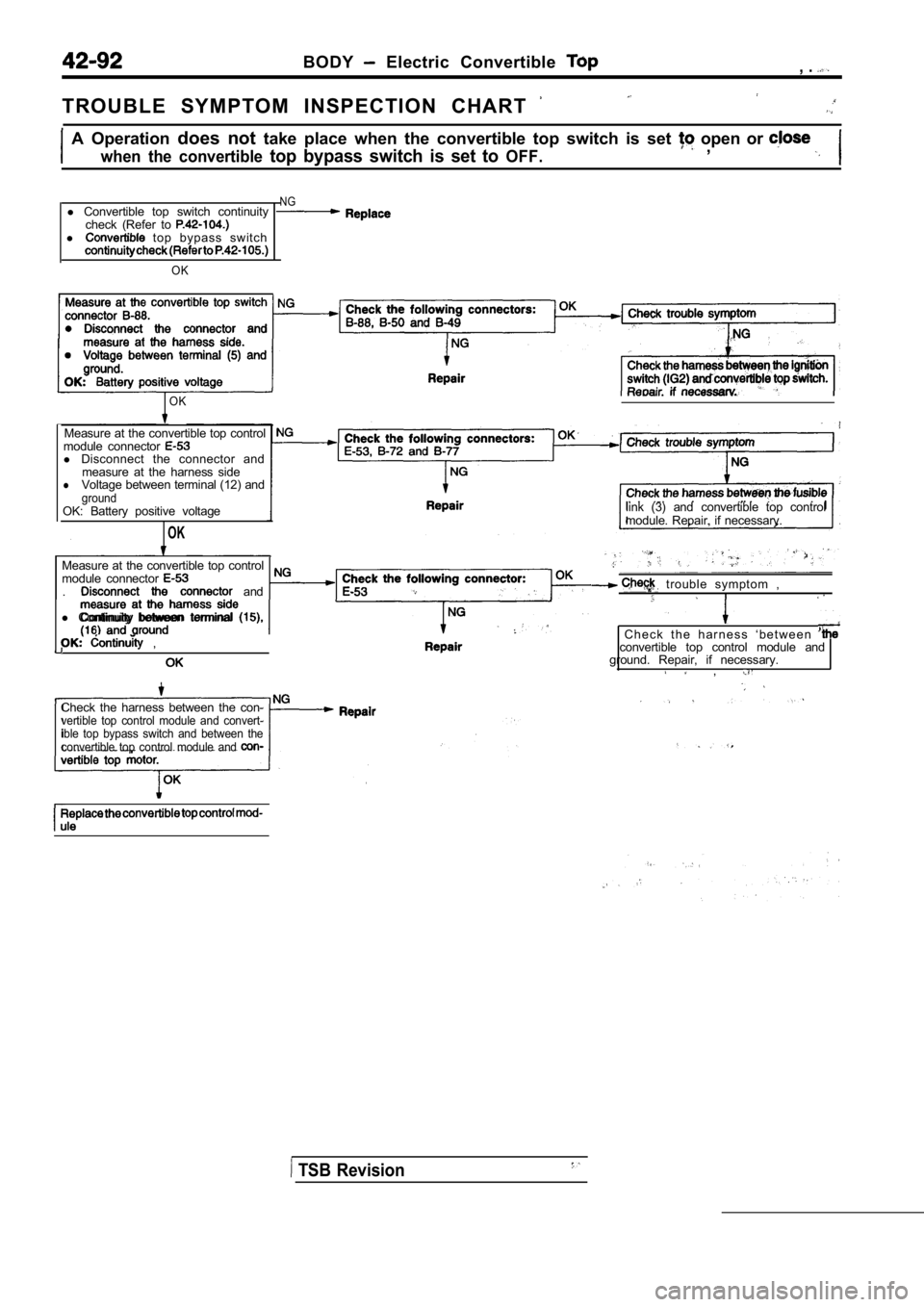
T R O U B L E S Y M P T O M I N S P E C T I O N C H A R T
A Operation does not take place when the convertible top switch is set open or
when the convertible top bypass switch is set to OFF. ,
l Convertible top switch continuity
check (Refer to
l top bypass switch
OK
NG
OK
Measure at the convertible top control
module connector
l Disconnect the connector and
measure at the harness side
lVoltage between terminal (12) andgroundOK: Battery positive voltage
OK
link (3) and convertible top control
module. Repair, if necessary.
Measure at the convertible top control
module connector
. and
l Continuity between terminal
,
Check the harness between the con-vertible top control module and convert-
ible top bypass switch and between the
convertible top control module and
trouble symptom ,
C h e c k t h e h a r n e s s ‘ b e t w e e n convertible top control module and
ground. Repair, if necessary.
,
TSB Revision
Page 1917 of 2103
BODY Electric Convertible TOP
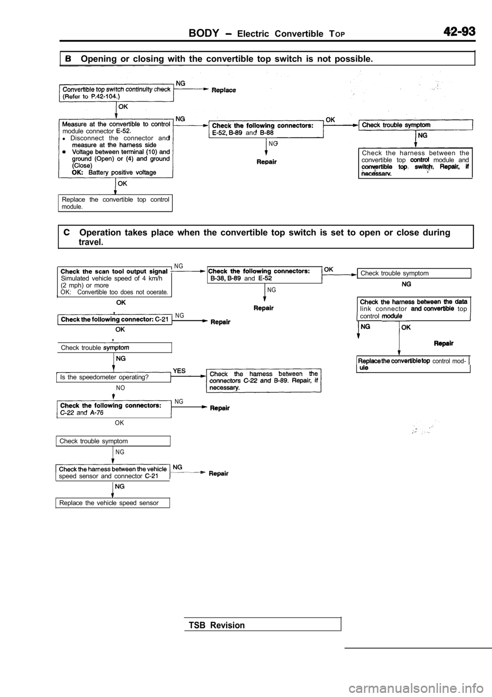
Opening or closing with the convertible top switch is not possible.
module connector
l Disconnect the connector and and
Replace the convertible top controlmodule.
N G
Check the harness between the
convertible top module and
Operation takes place when the convertible top swit ch is set to open or close during
travel.
NG
Simulated vehicle speed of 4 km/h and (2 mph) or moreOK: Convertible too does not ooerate.NG
Check trouble symptom
link connector topNG control
Check trouble
control mod-
Is the speedometer operating?
N O
NG
and
TSB Revision
OK
Check trouble symptom
N G
speed sensor and connector
Replace the vehicle speed sensor
Page 1918 of 2103
BODY Electric Convertible Top
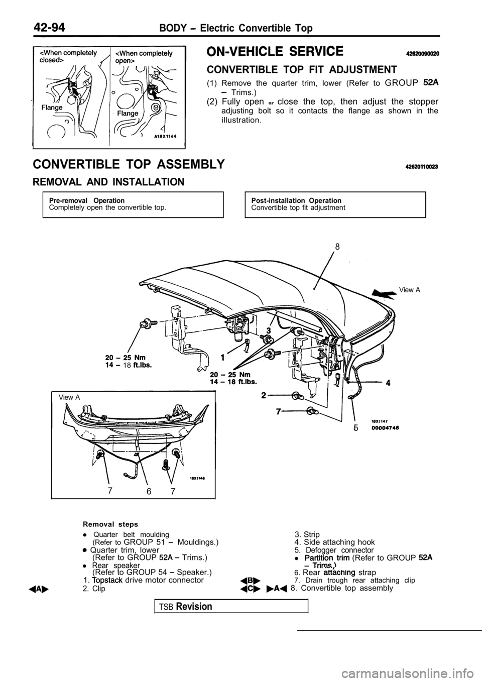
CONVERTIBLE TOP FIT ADJUSTMENT
(1) Remove the quarter trim, lower (Refer to GROUP
Trims.)
(2) Fully open orclose the top, then adjust the stopper
adjusting bolt so it contacts the flange as shown in the
illustration.
CONVERTIBLE TOP ASSEMBLY
REMOVAL AND INSTALLATION
Pre-removal OperationCompletely open the convertible top.Post-installation OperationConvertible top fit adjustment
8
View A
18
View A
76 7
5
Removal steps
3. Strip
l
Quarter belt moulding
(Refer to GROUP 51
Mouldings.) Quarter trim, lower
(Refer to GROUP Trims.)l Rear speaker(Refer to GROUP 54 Speaker.)
1. drive motor connector
2. Clip
4. Side attaching hook5. Defogger connectorl (Refer to GROUP
6. Rear strap
7. Drain trough rear attaching clip
8. Convertible top assembly
TSBRevision
Page 1919 of 2103
BODY Electric Convertible
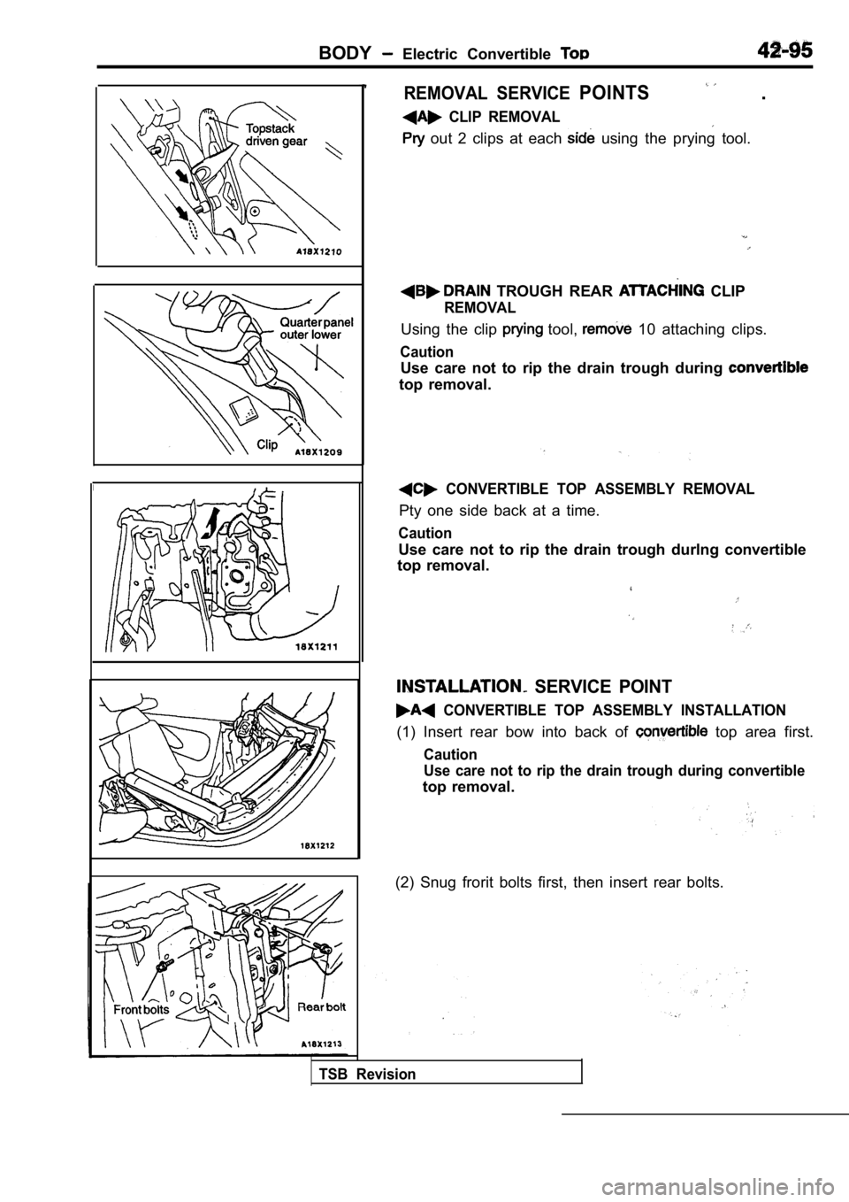
REMOVAL SERVICE POINTS .
CLIP REMOVAL
out 2 clips at each using the prying tool.
TROUGH REAR CLIP
REMOVAL
Using the clip tool, 10 attaching clips.
Caution
Use care not to rip the drain trough during
top removal.
CONVERTIBLE TOP ASSEMBLY REMOVAL
Pty one side back at a time.
Caution
Use care not to rip the drain trough durlng convertible
top removal.
TSB Revision
SERVICE POINT
CONVERTIBLE TOP ASSEMBLY INSTALLATION
(1) Insert rear bow into back of top area first.
Caution
Use care not to rip the drain trough during convert ible
top removal.
(2) Snug frorit bolts first, then insert rear bolts .
Page 1920 of 2103
42-96BODY Electric Convertible
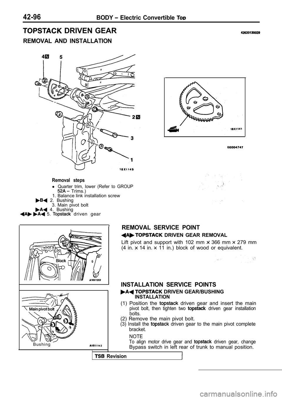
DRIVEN GEAR
REMOVAL AND INSTALLATION
Removal steps
l Quarter trim, lower (Refer to GROUP Trims.)
1. Balance link installation screw
2. Bushing
3. Main pivot bolt
4. Bushing 5. driven gear
B u s h i n g
REMOVAL SERVICE POINT
DRIVEN GEAR REMOVAL
Lift pivot and support with 102 mm
366 mm 279 mm
(4 in.
14 in. 11 in.) block of wood or equivalent.
INSTALLATION SERVICE POINTS
DRIVEN GEAR/BUSHING
INSTALLATION
(1) Position the driven gear and insert the main
pivot bolt, then tighten two driven gear installation
bolts.
(2) Remove the main pivot bolt.
(3) Install the driven gear to the main pivot complete
bracket.
NOTE
To align motor drive gear and driven gear, change
Bypass switch in left rear of trunk to manual posit ion.
Revision