MITSUBISHI SPYDER 1990 Service Repair Manual
Manufacturer: MITSUBISHI, Model Year: 1990, Model line: SPYDER, Model: MITSUBISHI SPYDER 1990Pages: 2103, PDF Size: 68.98 MB
Page 1871 of 2103
BODY Door
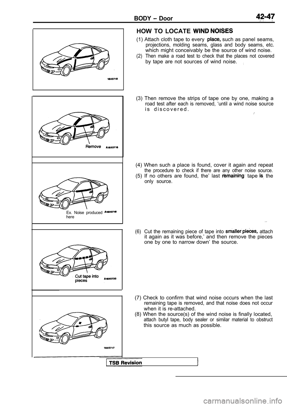
Ex. Noise produced here
HOW TO LOCATE
(1) Attach cloth tape to every such as panel seams,
projections, molding seams, glass and body seams, etc.
which might conceivably be the source of wind noise.
(2) Then make a road test to check that the places n ot covered
by tape are not sources of wind noise.
(3) Then remove the strips of tape one by one, making a
road test after each is removed, ‘until a wind noise source
i s d i s c o v e r e d .
(4) When such a place is found, cover it again and repeat
the procedure to check if there are any other noise source.
(5) If no others are found, the’ last tape the
only source.
(6)Cut the remaining piece of tape into attach
it again as it was before,’ and then remove the pieces
one by one to narrow down’ the source.
(7) Check to confirm that wind noise occurs when th e last
remaining tape is removed, and that noise does not occur
when it is re-attached.
(8) When the source(s) of the wind noise is finally located,
attach butyl tape, body sealer or similar material to obstruct
this source as much as possible.
Page 1872 of 2103
42-48BODY Door
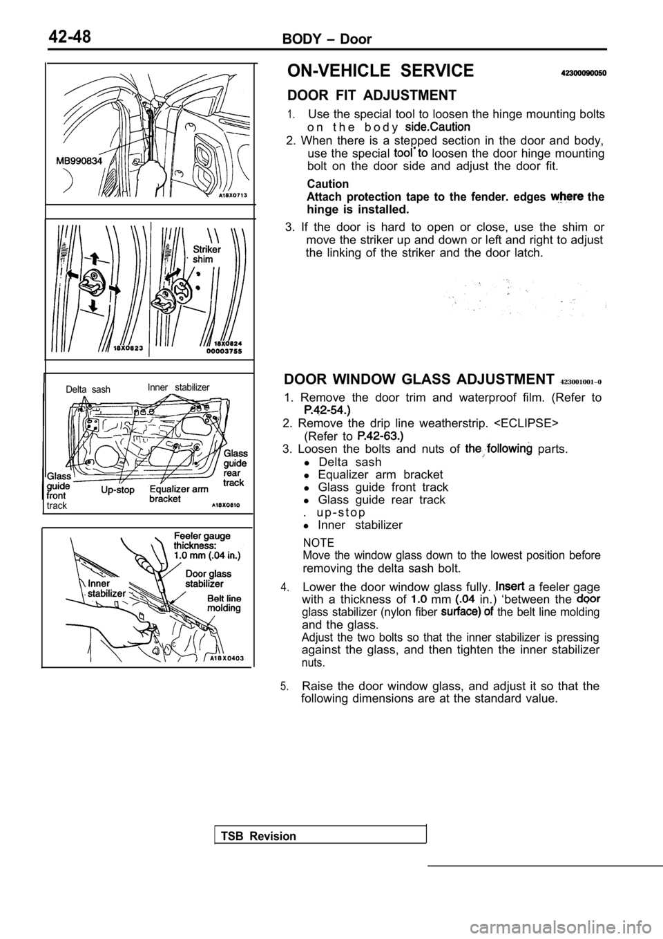
Delta sashInner stabilizer
track
ON-VEHICLE SERVICE
DOOR FIT ADJUSTMENT
1.Use the special tool to loosen the hinge mounting b
olts
o n t h e b o d y
2. When there is a stepped section in the door and body,
use the special
loosen the door hinge mounting
bolt on the door side and adjust the door fit.
Caution
Attach protection tape to the fender. edges
the
hinge is installed.
3. If the door is hard to open or close, use the sh im or
move the striker up and down or left and right to a djust
the linking of the striker and the door latch.
DOOR WINDOW GLASS ADJUSTMENT 423001001~0
1. Remove the door trim and waterproof film. (Refer to
2. Remove the drip line weatherstrip.
(Refer to
3. Loosen the bolts and nuts of parts.
l Delta sash
l Equalizer arm bracket
l Glass guide front track
l Glass guide rear track
. u p - s t o p
l Inner stabilizer
NOTE
Move the window glass down to the lowest position b efore
removing the delta sash bolt.
4.Lower the door window glass fully. a feeler gage
with a thickness of
mm in.) ‘between the
glass stabilizer (nylon fiber the belt line molding
and the glass.
Adjust the two bolts so that the inner stabilizer i s pressing
against the glass, and then tighten the inner stabi lizer
nuts.
5.Raise the door window glass, and adjust it so that the
following dimensions are at the standard value.
TSB Revision
Page 1873 of 2103
.
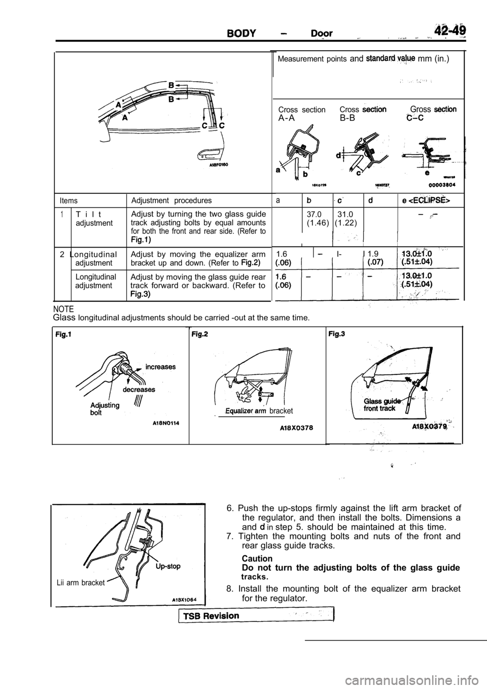
Measurement points and mm (in.)
Cross section
A - A
Cross
B-B
Gross
Items
1T i l t
adjustmentAdjustment procedures
Adjust by turning the two glass guide
track adjusting bolts by equal amounts
for both the front and rear side. (Refer to
2 Longitudinal
Adjust by moving the equalizer arm
adjustment bracket up and down. (Refer to
LongitudinalAdjust by moving the glass guide rear
adjustmenttrack forward or backward. (Refer to
a
37.031.0
(1.46) (1.22)
I I
1.6 I-I 1.9
NOTE
Glass
longitudinal adjustments should be carried -out at the same time.
bracket
Lii arm bracket
6. Push the up-stops firmly against the lift arm br acket of
the regulator, and then install the bolts. Dimensio ns a
and
in step 5. should be maintained at this time.
7. Tighten the mounting bolts and nuts of the front and
rear glass guide tracks.
Caution
Do not turn the adjusting bolts of the glass guide
tracks.
8. Install the mounting bolt of the equalizer arm b racket
for the regulator.
Page 1874 of 2103
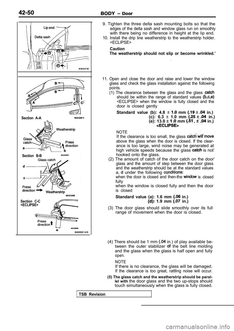
Section A-A
Section B-B
Section C-C
9. Tighten the three delta sash mounting bolts so t hat the
edges of the delta sash and window glass run on smo othly
with there being no difference in height at the lip end.
10. Install the drip line weatherstrip to the weatherstrip holder.
Caution
The weatherstrip should not slip or become wrinkled .’
11. Open and close the door and raise and lower the window
glass and check the glass installation against the following
points.
(1) The clearance between the glass and the glass
should be within the range of standard values
door is closed gently
Standard value (b): 4.8 mm in.)
(c): 6.3
1.0 mm in.)
(e): 13.0
mm , in.)
NOTE
If the clearance is too small, the glass
above the glass when the door is closed. If the cle ar-
ance is too large, wind noise may be generated at
high vehicle speeds because the glass
is not’
hooked onto the glass.
(2) The amount of catch of the door catch on the do or’
glass and the amount of step between the door glass
and the weatherstrip should be at the standard valu es
a, under the following
when the door is closed and then-the is closed
fully
when the window is closed fully and then the door
is closed
Standard value (a): 1.6 mm in.)
1.9 mm in.)
(3) The door glass should slide smoothly over its f ull
range of movement when the door is closed.
(4) There should be 1 mm
in.) of play available be-
tween the outer stabilizer
the belt line molding
and the glass when the glass is half open and fully
open.
NOTE
If there is no clearance, the glass will be damaged .
If the clearance is too great, rattling noise will occur.
(5) The glass catch and the weatherstrip should be paral-
lel with the door glass and the two up-stops should
touch simultaneously when the glass is fully closed .
TSB Revision
Page 1875 of 2103
B O D Y Door
U P
Section A-A
0 0 0 0 0 1 4 5
D O W N
6 9 8 0 0 4 6
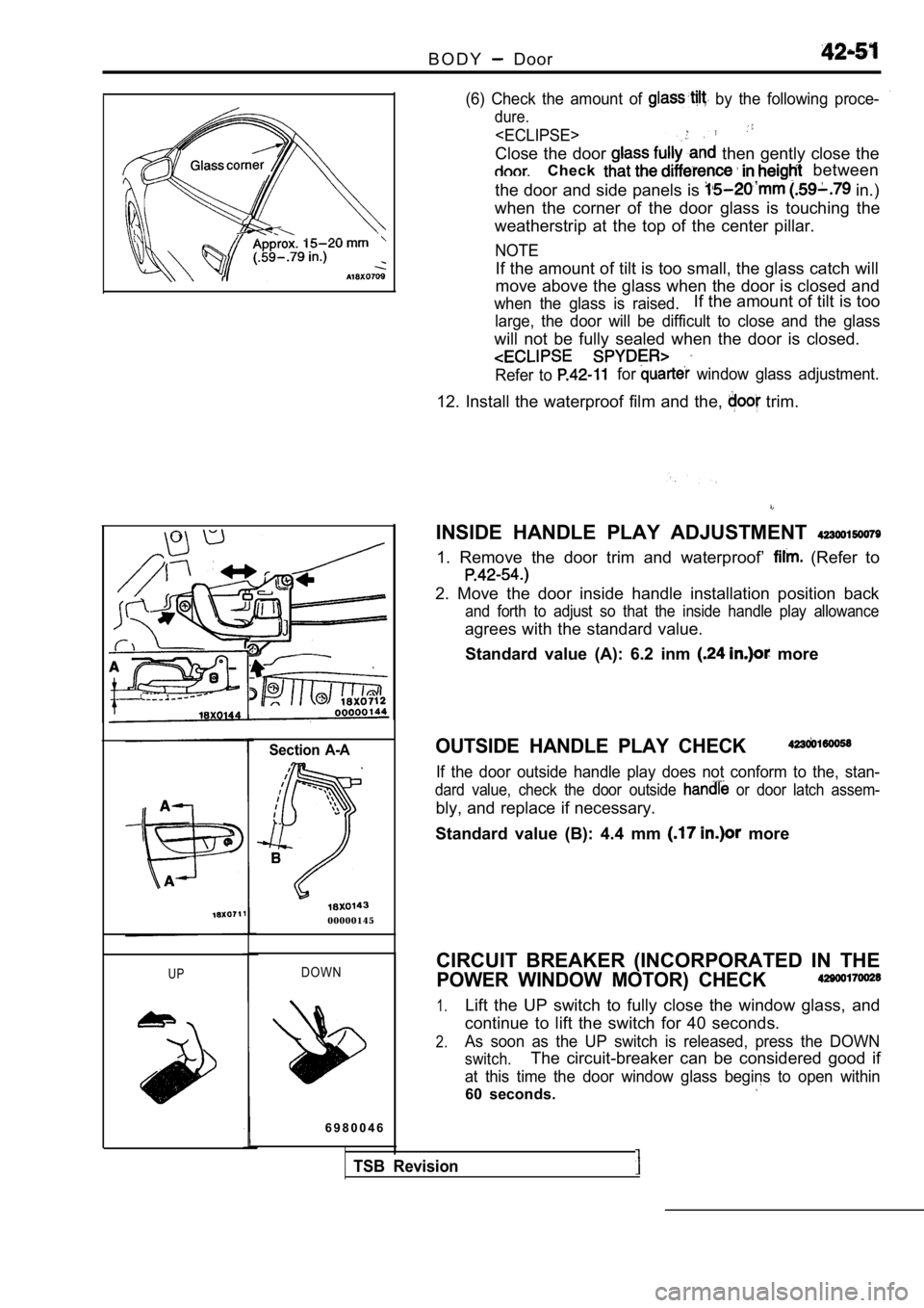
(6) Check the amount of by the following proce-
dure.
Close the door then gently close the
Check between
the door and side panels is
in.)
when the corner of the door glass is touching the
weatherstrip at the top of the center pillar.
NOTE
If the amount of tilt is too small, the glass catch will
move above the glass when the door is closed and
when the glass is raised.If the amount of tilt is too
large, the door will be difficult to close and the glass
will not be fully sealed when the door is closed.
Refer to for window glass adjustment.
12. Install the waterproof film and the, trim.
INSIDE HANDLE PLAY ADJUSTMENT
1. Remove the door trim and waterproof’ (Refer to
2. Move the door inside handle installation positio n back
and forth to adjust so that the inside handle play allowance
agrees with the standard value.
Standard value (A): 6.2 inm
more
OUTSIDE HANDLE PLAY CHECK
If the door outside handle play does not conform to the, stan-
dard value, check the door outside or door latch assem-
bly, and replace if necessary.
Standard value (B): 4.4 mm
more
TSB Revision
CIRCUIT BREAKER (INCORPORATED IN THE
POWER WINDOW MOTOR) CHECK
1.Lift the UP switch to fully close the window glass, and
continue to lift the switch for 40 seconds.
2.As soon as the UP switch is released, press the DOW N
switch.The circuit-breaker can be considered good if
at this time the door window glass begins to open within
60 seconds.
Page 1876 of 2103
42-52BODY Door
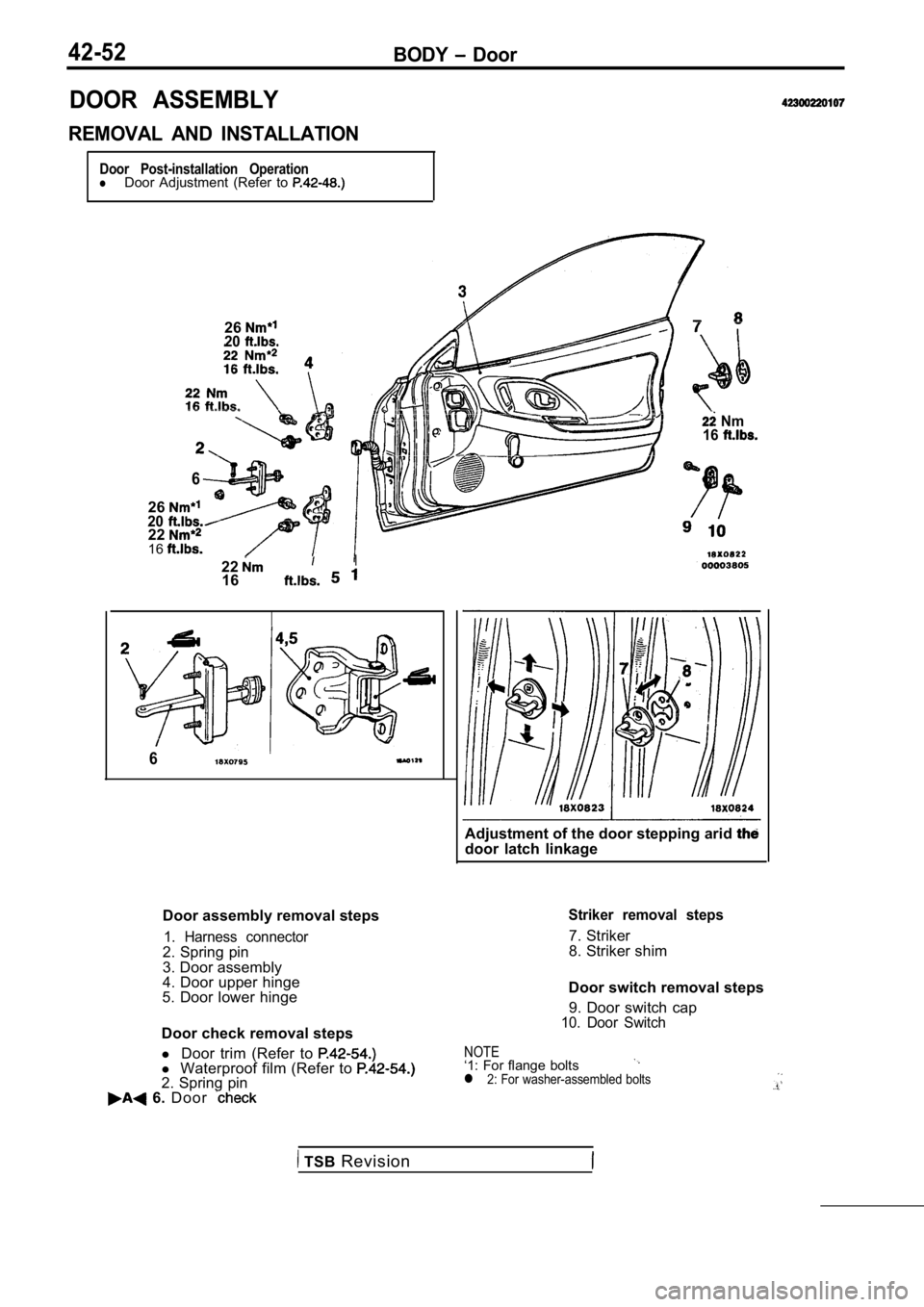
DOOR ASSEMBLY
REMOVAL AND INSTALLATION
Door Post-installation OperationlDoor Adjustment (Refer to
2620
6
26202216
22I
16
6
Door assembly removal steps
1. Harness connector2. Spring pin
3. Door assembly
4. Door upper hinge
5. Door lower hinge
Door check removal steps
l Door trim (Refer to
l Waterproof film (Refer to 2. Spring pin 6. D o o r
Nm
16
Adjustment of the door stepping arid door latch linkage
Striker removal steps
7. Striker
8. Striker shim
Door switch removal steps 9. Door switch cap
10. Door Switch
NOTE‘1: For flange boltsl 2: For washer-assembled bolts
TSB Revision
Page 1877 of 2103
BODY Door
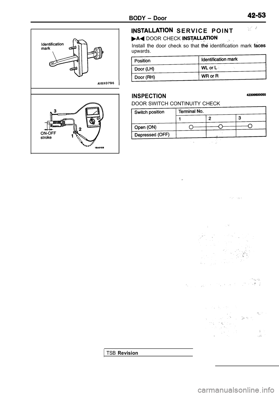
S E R V I C E P O I N T
DOOR CHECK
Install the door check so that identification mark
upwards.
INSPECTION
DOOR SWITCH CONTINUITY CHECK
TSBRevision
Page 1878 of 2103
BODY Door
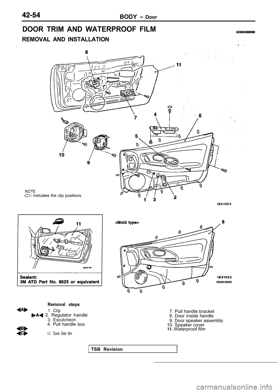
DOOR TRIM AND WATERPROOF FILM
REMOVAL AND INSTALLATION.
NOTE Indicates the clip positionsTSB Revision
Removal steps
1.Clip 2. Regulator handle
3.Escutcheon4. Pull handle box
5.6 .Cover Door trim
7. Pull handle bracket
8. Door inside handle
9. Door speaker assembly
10. Speaker cover
Waterproof film
Page 1879 of 2103
BODY Door
0 0 0 0 0 1 2 4
Front of vehicle
Cover
section
Door inside handle
l i n e
Front of vehicle
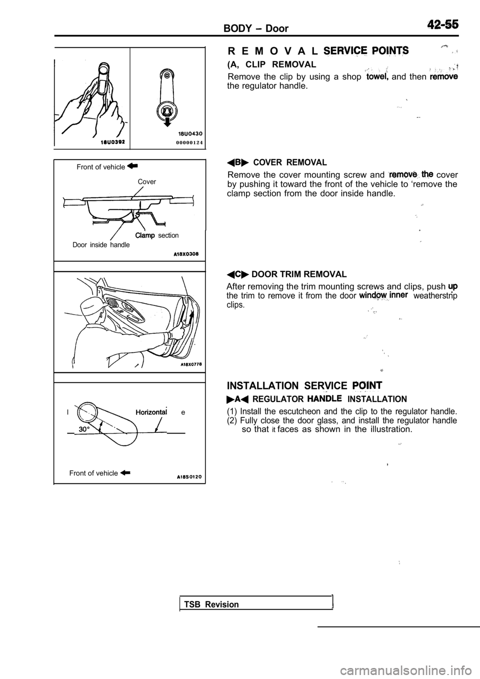
R E M O V A L
(A, CLIP REMOVAL
Remove the clip by using a shop and then
the regulator handle.
COVER REMOVAL
Remove the cover mounting screw and cover
by pushing it toward the front of the vehicle to ‘r emove the
clamp section from the door inside handle.
DOOR TRIM REMOVAL
After removing the trim mounting screws and clips, push
the trim to remove it from the door weatherstnp
clips.
INSTALLATION SERVICE
REGULATOR INSTALLATION
(1) Install the escutcheon and the clip to the regulator handle.
(2) Fully close the door glass, and install the reg ulator handle
so that itfaces as shown in the illustration.
,
TSB Revision
Page 1880 of 2103
BODY Door
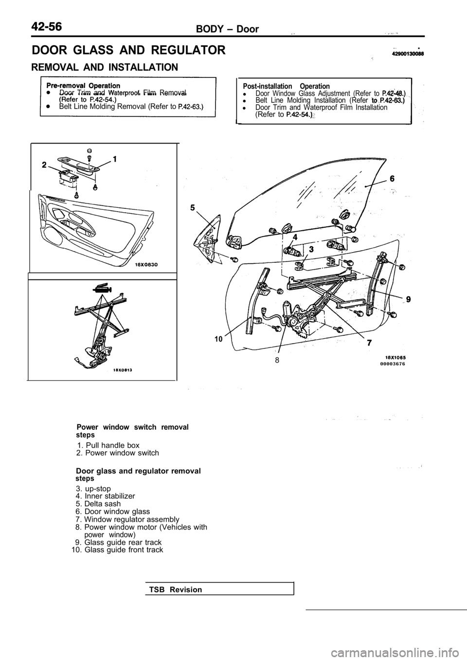
DOOR GLASS AND REGULATOR
REMOVAL AND INSTALLATION
.
Door Trim and Film Removal
Belt Line Molding Removal (Refer to
10
Post-installation OperationlDoor Window Glass Adjustment (Refer to lBelt Line Molding Installation (Refer lDoor Trim and Waterproof Film Installation(Refer to
TSB Revision8
0 0 0 0 3 6 7 6
Power window switch removalsteps
1. Pull handle box
2. Power window switch
Door glass and regulator removal
steps
3. up-stop
4. Inner stabilizer
5. Delta sash
6. Door window glass
7. Window regulator assembly
8. Power window motor (Vehicles with
power window)9. Glass guide rear track
10. Glass guide front track