MITSUBISHI SPYDER 1990 Service Repair Manual
SPYDER 1990
MITSUBISHI
MITSUBISHI
https://www.carmanualsonline.info/img/19/57345/w960_57345-0.png
MITSUBISHI SPYDER 1990 Service Repair Manual
Trending: oil viscosity, radio, low oil pressure, height adjustment, high beam, steering wheel adjustment, cruise control
Page 1881 of 2103
B O D Y Door
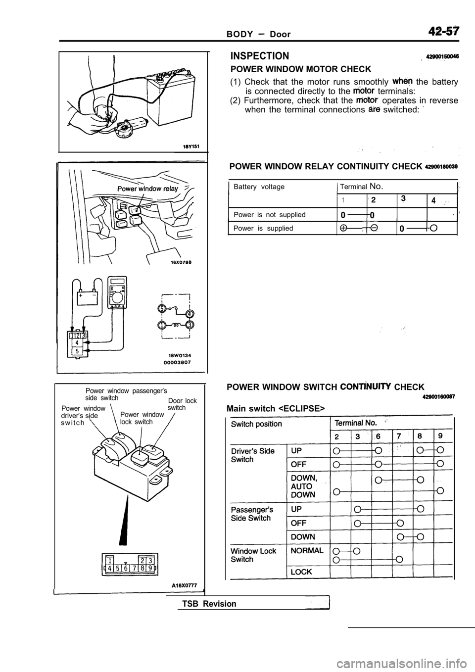
Power window passenger’s
side switch Door lock
Power window
switch
driver’s sidePower window
s w i t c hlock switch
INSPECTION
POWER WINDOW MOTOR CHECK
(1) Check that the motor runs smoothly
the battery
is connected directly to the
terminals:
(2) Furthermore, check that the
operates in reverse
when the terminal connections
switched:
POWER WINDOW RELAY CONTINUITY CHECK
Battery voltage Terminal No.
Power is not supplied
Power is supplied
14
0 0
0
POWER WINDOW SWITCH CHECK
Main switch
TSB Revision
Page 1882 of 2103
BODY Door
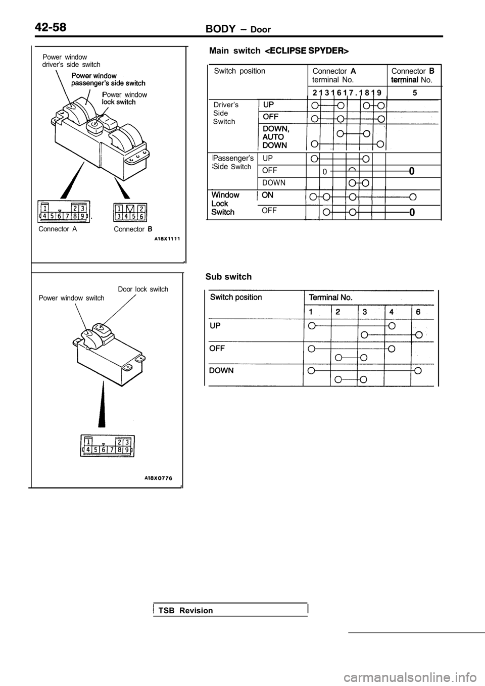
Power window
driver’s side switch
Power window
Connector A Connector
Power window switch Door lock switch
Main switch
Switch position
ConnectorAConnector
terminal No. No.
2 1 3 1 6 1 7 . 1 8 1 9 5
Driver’s
Side
Switch
Passenger’s
Side
Switch
UP
OFF00
DOWN
OFF0
Sub switch
TSB Revision
Page 1883 of 2103
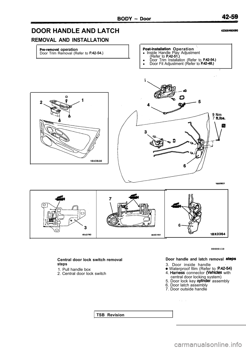
DOOR HANDLE AND LATCH
REMOVAL AND INSTALLATION
operationDoor Trim Removal (Refer to Operation l Inside Handle Play Adjustment(Refer to
lDoor Trim Installation (Refer to lDoor Fit Adjustment (Refer to
7
9 Nm7
Central door lock switch removal
steps
1. Pull handle box
2. Central door lock switch
6
0 0 0 0 0 1 5 0
Door handle and latch removal
3. Door inside handle Waterproof film (Refer to 4. connector with
central door locking system)
5. Door lock key
assembly
6. Door latch assembly 7. Door outside handle
TSB Revision
Page 1884 of 2103
BODY Door
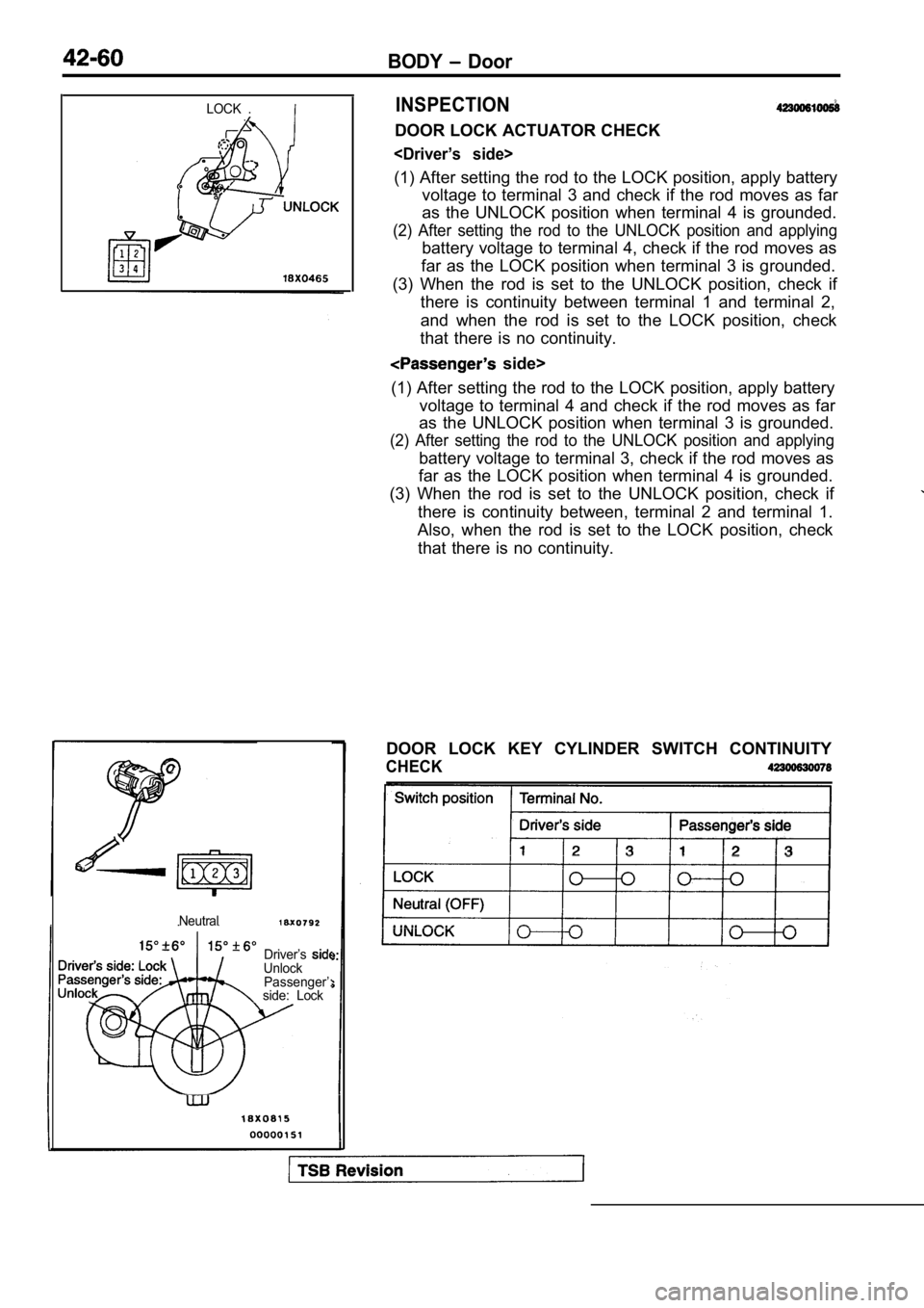
LOCK .INSPECTION
DOOR LOCK ACTUATOR CHECK
(1) After setting the rod to the LOCK position, apply battery
voltage to terminal 3 and check if the rod moves as far
as the UNLOCK position when terminal 4 is grounded.
(2) After setting the rod to the UNLOCK position an d applying
battery voltage to terminal 4, check if the rod moves as
far as the LOCK position when terminal 3 is grounde d.
(3) When the rod is set to the UNLOCK position, che ck if
there is continuity between terminal 1 and terminal 2,
and when the rod is set to the LOCK position, check
that there is no continuity.
side>
(1) After setting the rod to the LOCK position, app ly battery
voltage to terminal 4 and check if the rod moves as far
as the UNLOCK position when terminal 3 is grounded.
(2) After setting the rod to the UNLOCK position an d applying
battery voltage to terminal 3, check if the rod moves as
far as the LOCK position when terminal 4 is grounde d.
(3) When the rod is set to the UNLOCK position, che ck if
there is continuity between, terminal 2 and termina l 1.
Also, when the rod is set to the LOCK position, che ck
that there is no continuity.
Neutral
Driver’sUnlock Passenger’:
side: Lock
DOOR LOCK KEY CYLINDER SWITCH CONTINUITY
CHECK
Page 1885 of 2103
BODY Door
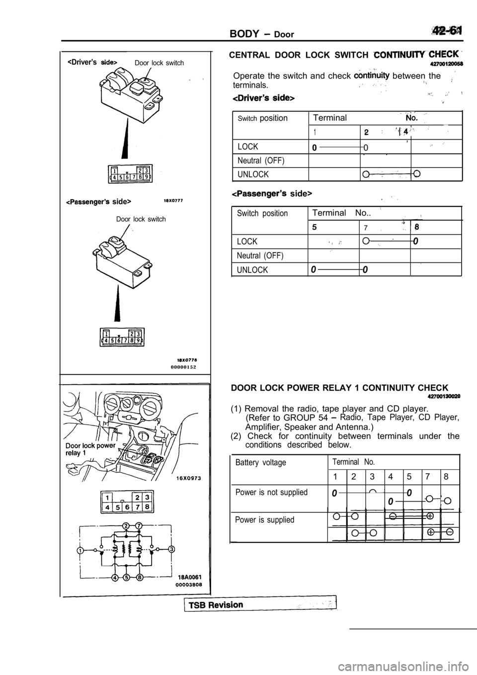
CENTRAL DOOR LOCK SWITCH
side>
Door lock switch
0 0 0 0 0 1 5 2 Operate the switch and check
between the
terminals..
Switchposition
LOCK
Neutral (OFF)
UNLOCK
Terminal
1,
0 0
. .
side>
,
Switch positionTerminal No..
7,
LOCK0
Neutral (OFF).
UNLOCK00
DOOR LOCK POWER RELAY 1 CONTINUITY CHECK
(1) Removal the radio, tape player and CD player. (Refer to GROUP 54
Radio, Tape Player, CD Player,
Amplifier, Speaker and Antenna.)
(2) Check for continuity between terminals under th e
conditions described below.
Battery voltageTerminal No.
1 2 3 4 5 7 8
Power is not supplied00
0
Power is supplied
Page 1886 of 2103
BODY Door
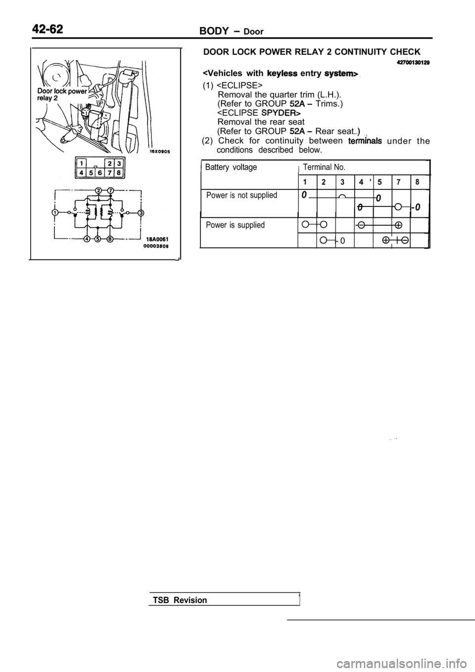
DOOR LOCK POWER RELAY 2 CONTINUITY CHECK
(1) Removal the quarter trim (L.H.).
(Refer to GROUP
Trims.)
Removal the rear seat
(Refer to GROUP
Rear seat.
(2) Check for continuity between u n d e r t h e
conditions described below.
Battery voltageITerminal No.
2 34 ’ 57 8
Powerisnotsupplied00
0 -0
Power is supplied
- 0
TSB Revision1
Page 1887 of 2103
Door
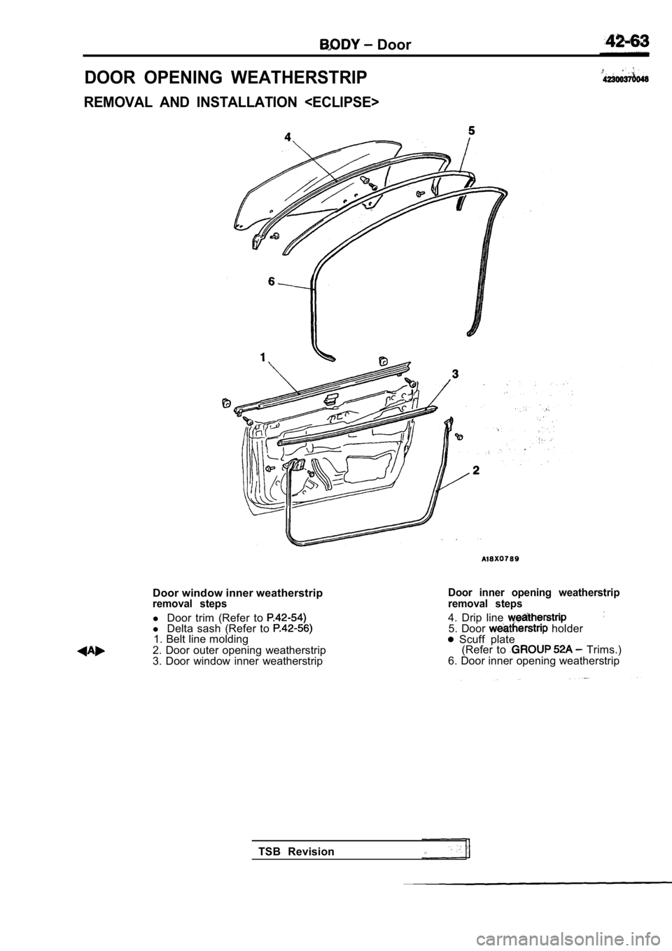
DOOR OPENING WEATHERSTRIP
REMOVAL AND INSTALLATION
Door window inner weatherstripremoval steps
l Door trim (Refer to l Delta sash (Refer to 1. Belt line molding
2. Door outer opening weatherstrip
3. Door window inner weatherstrip
Door inner opening weatherstrip
removal steps
4. Drip line 5. Door holder Scuff plate (Refer to Trims.)
6. Door inner opening weatherstrip
TSB Revision
Page 1888 of 2103
BODY Door
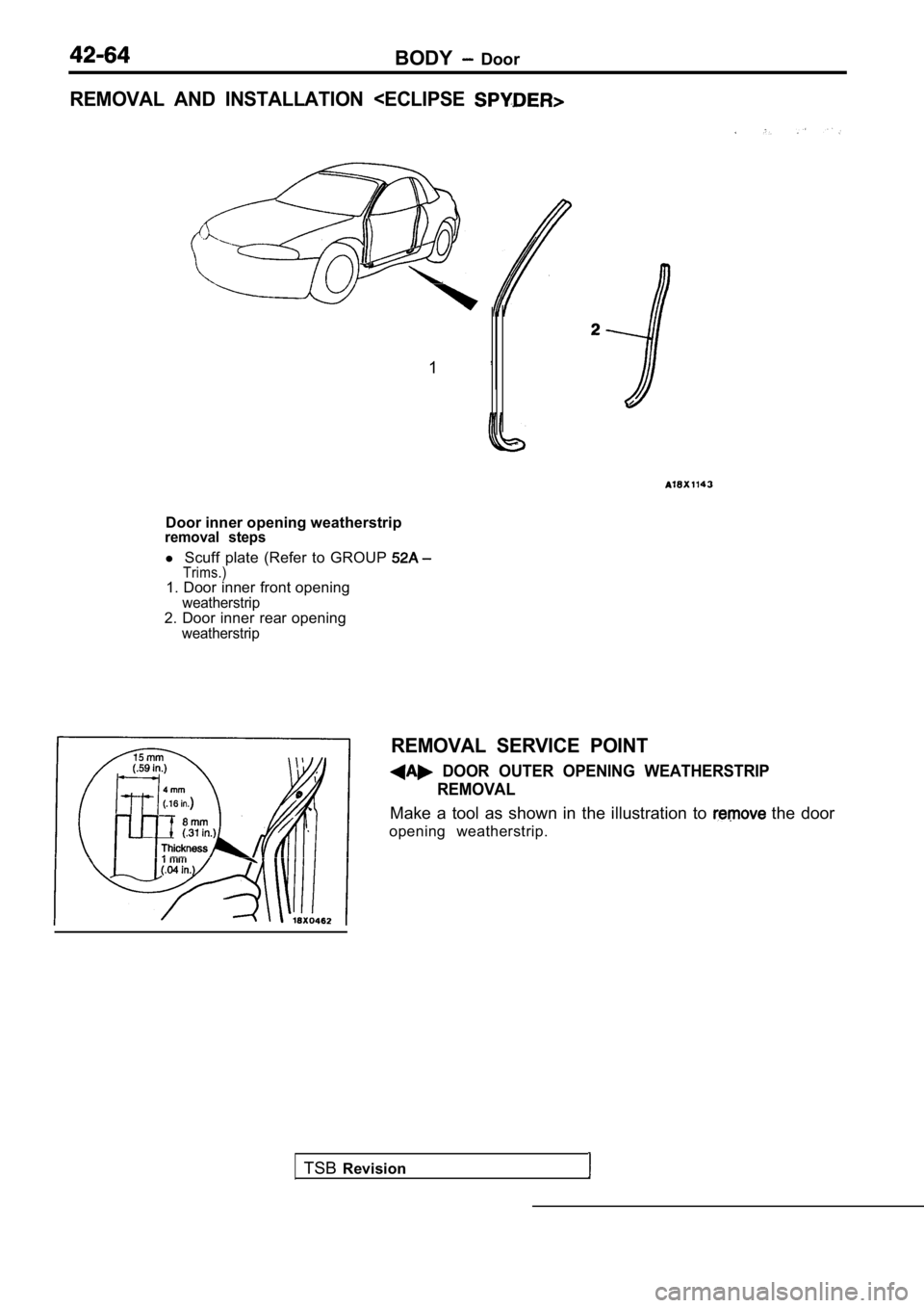
REMOVAL AND INSTALLATION
1 ’
Door inner opening weatherstripremoval steps
l Scuff plate (Refer to GROUP Trims.)1. Door inner front openingweatherstrip2. Door inner rear openingweatherstrip
TSB Revision
REMOVAL SERVICE POINT
DOOR OUTER OPENING WEATHERSTRIP
REMOVAL
Make a tool as shown in the illustration to the door
opening weatherstrip.
Page 1889 of 2103
BODY
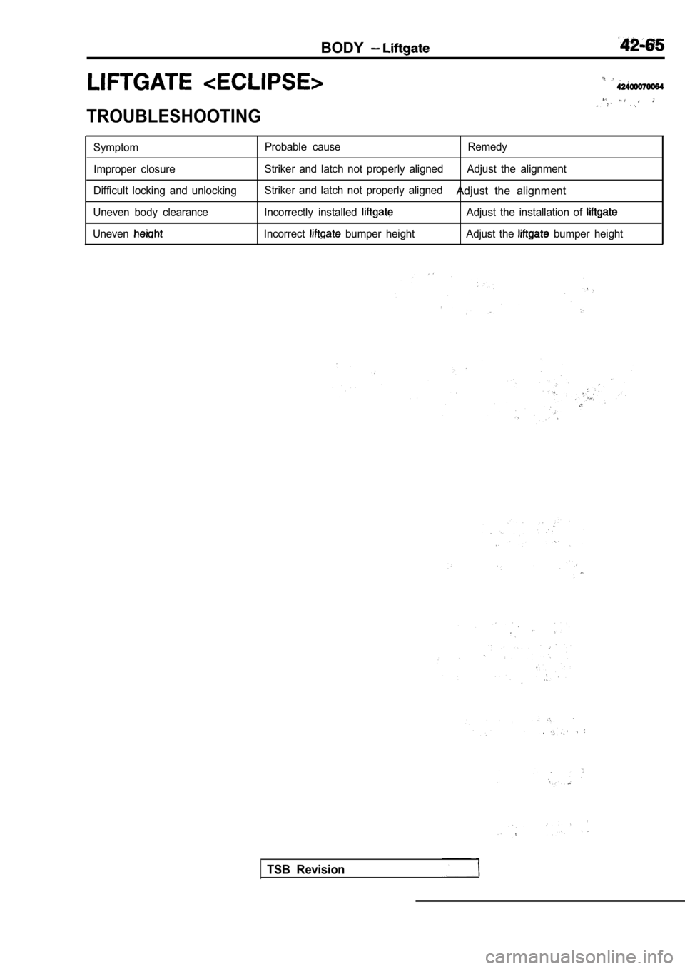
TROUBLESHOOTING
SymptomImproper closure
Difficult locking and unlocking
Uneven body clearance
UnevenProbable cause Remedy
Striker and latch not properly aligned Adjust the al ignment
Striker and latch not properly aligned
Adjust the alignment
Incorrectly installed Adjust the installation of
Incorrect bumper height Adjust the bumper height
TSB Revision
Page 1890 of 2103
B O D Y
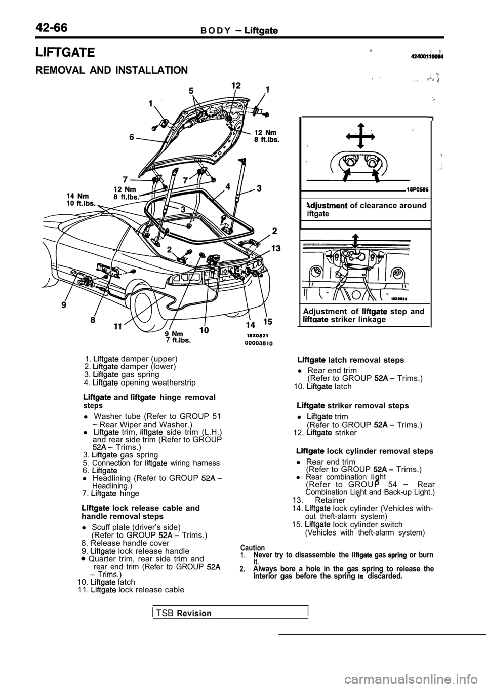
REMOVAL AND INSTALLATION
7
1. damper (upper)
2. damper (lower)
3. gas spring
4. opening weatherstrip
and hinge removal
steps
l Washer tube (Refer to GROUP 51 Rear Wiper and Washer.)
l trim, side trim (L.H.)
and rear side trim (Refer to GROUP
Trims.)
3. gas spring5. Connection for wiring harness6.l Headlining (Refer to GROUP Headlining.)7. hinge
lock release cable and
handle removal steps
l Scuff plate (driver’s side)
(Refer to GROUP
Trims.)
8. Release handle cover
9.
lock release handle Quarter trim, rear side trim andrear end trim (Refer to GROUP Trims.)10. latch
11. lock release cable ,
, ,
of clearance around
iftgate
Adjustment of step and striker linkage
latch removal steps
l Rear end trim
(Refer to GROUP
Trims.)
10. latch
striker removal steps
l
trim
(Refer to GROUP Trims.)
12. striker
lock cylinder removal steps
l Rear end trim
(Refer to GROUP
Trims.)l Rear combination Iiht( R e f e r t o G R O U54 RearCombination Liaht and Back-up Light.)13. Retainer
14. lock cylinder (Vehicles with-out theft-alarm system)
15. lock cylinder switch(Vehicles with theft-alarm system)
Caution1.Never try to disassemble the gas or burnit.2.Always bore a hole in the gas spring to release the interior gas before the spring discarded.
TSB Revision
Trending: steering, service reset, wheel alignment, automatic transmission fluid, fog light, jacking, fuel fill door release
