MITSUBISHI SPYDER 1990 Service Repair Manual
Manufacturer: MITSUBISHI, Model Year: 1990, Model line: SPYDER, Model: MITSUBISHI SPYDER 1990Pages: 2103, PDF Size: 68.98 MB
Page 211 of 2103
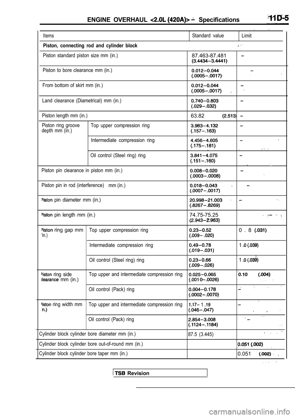
ENGINE OVERHAUL Specifications
Items
Piston, connecting rod and cylinder block
Piston standard piston size mm (in.)
Standard valueLimit
,
87.463-87.481
Piston to bore clearance mm (in.)
From bottom of skirt mm (in.)
.
Land clearance (Diametrical) mm (in.)
Piston length mm (in.)
Piston ring groove Top upper compression ring
depth mm (in.)
Intermediate compression ring
Oil control (Steel ring) ring
Piston pin clearance in piston mm (in.)
Piston pin in rod (interference) mm (in.)
63.82
.
,
,
pin diameter mm (in.)
pin length mm (in.)74.75-75.25
ring gap mmTop upper compression ring0 . 8
‘in.)
Intermediate compression ring1
Oil control (Steel ring) ring1
ring sideTop upper and intermediate compression ring
mm (in.)
Oil control (Pack) ring
ring width mmTop upper and intermediate compression ring 1
. ,
Oil control (Pack) ring
Cylinder block cylinder bore diameter mm (in.)
Cylinder block cylinder bore out-of-round mm (in.)
Cylinder block cylinder bore taper mm (in.) 87.5 (3.445)
0.051 .
Revision
Page 212 of 2103
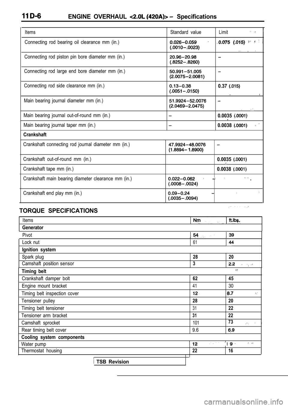
ENGINE OVERHAUL Specifications
Items
Connecting rod bearing oil clearance mm (in.)Standard value
Limit
Connecting rod piston pin bore diameter mm (in.)
Connecting rod large end bore diameter mm (in.)
Connecting rod side clearance mm (in.)
Main bearing journal diameter mm (in.)0.37
.
Main bearing journal out-of-round mm (in.)
Main bearing journal taper mm (in.)
Crankshaft
0.0035.
0.0038
Crankshaft connecting rod journal diameter mm (in.)
Crankshaft out-of-round mm (in.)
Crankshaft tape mm (in.)
Crankshaft main bearing diameter clearance mm (in.)0.0035
0.0038
.
Crankshaft end play mm (in.)
TORQUE SPECIFICATIONS
Items
Generator
Pivot
Lock nut61
Ignition system
Spark plug28 20
Camshaft position sensor3
Timing belt
Crankshaft damper bolt62 45
Engine mount bracket4130
Timing belt inspection cover
Tensioner pulley28 20
Timing belt tensioner3122
Tensioner arm bracket3122
Camshaft sprocket10173
Rear timing belt cover 9.6
Cooling system components
Water pump
Thermostat housing2216
TSB Revision
Page 213 of 2103
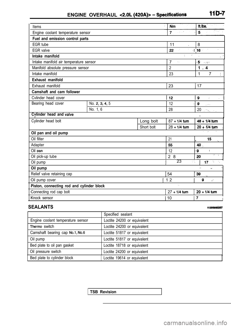
ENGINE OVERHAUL
Items
Engine coolant temperature sensor
Fuel and emission control parts
EGR tube
EGR valve
Intake manifold
11 8
Intake manifold air temperature sensor
Manifold absolute pressure sensor
Intake manifold
Exhaust manifold
Exhaust manifold
Camshaft and cam follower
Cvlinder head cover
Bearing head cover
No.5 12
No.1, 628 20
Cvlinder head and
valve.
7
21 . 4
231 7 :
23 17
Cylinder head bolt
Oil pan and oil pump
Oil filter
Adapter
Oil
Oil pick-up tube
Oil pump
Oil pump
Relief valve retaining cap
Long bolt87
Short bolt2820
21,
12
2 8
23
54
Oil pump cover
Piston, connecting rod and cylinder block
Connecting rod cap bolt
1 2
2720
Knock sensor 10I
SEALANTS
Engine coolant temperature sensor
switch
Camshaft bearing cap
Oil pump
Bed plate to oil pan gasket
Oil pressure switch Bed plate to cylinder block Specified sealant
Loctite 24200 or equivalent
Loctite 24200 or equivalent
Loctite 51817 or equivalent
Loctite 51817 or equivalent
Loctite 18718 or equivalent
Loctite 24200 or equivalent
Loctite 19614 or equivalent
TSB Revision
Page 214 of 2103
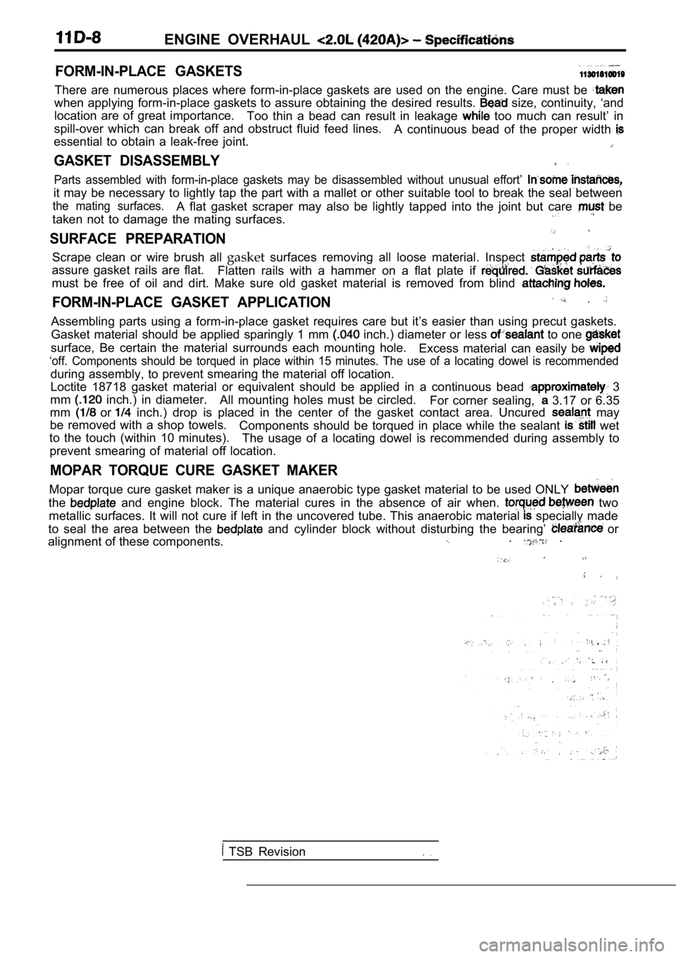
ENGINE OVERHAUL
FORM-IN-PLACE GASKETS
There are numerous places where form-in-place gaskets are used on the engine. Care must be
when applying form-in-place gaskets to assure obtaining the desired results. size, continuity, ‘and
location are of great importance. Too thin a bead can result in leakage
too much can result’ in
spill-over which can break off and obstruct fluid f eed lines.
A continuous bead of the proper width
essential to obtain a leak-free joint.
GASKET DISASSEMBLY
Parts assembled with form-in-place gaskets may be d isassembled without unusual effort’
it may be necessary to lightly tap the part with a mallet or other suitable tool to break the seal between
the mating surfaces.A flat gasket scraper may also be lightly tapped in to the joint but care be
taken not to damage the mating surfaces.
SURFACE PREPARATION
Scrape clean or wire brush all gasketsurfaces removing all loose material. Inspect
assure gasket rails are flat.
Flatten rails with a hammer on a flat plate if
must be free of oil and dirt. Make sure old gasket material is removed from blind
FORM-IN-PLACE GASKET APPLICATION
Assembling parts using a form-in-place gasket requires care but it’s easier than using precut gaskets.
Gasket material should be applied sparingly 1 mm
inch.) diameter or less to one
surface, Be certain the material surrounds each mou nting hole.
Excess material can easily be
‘off. Components should be torqued in place within 15 minutes. The use of a locating dowel is recommen ded
during assembly, to prevent smearing the material off location.
Loctite 18718 gasket material or equivalent should be applied in a continuous bead
3
mm
inch.) in diameter. All mounting holes must be circled.
For corner sealing, 3.17 or 6.35
mm
or inch.) drop is placed in the center of the gasket contact area. Uncured may
be removed with a shop towels. Components should be torqued in place while the sea lant
wet
to the touch (within 10 minutes). The usage of a locating dowel is recommended during assembly to
prevent smearing of material off location.
MOPAR TORQUE CURE GASKET MAKER
Mopar torque cure gasket maker is a unique anaerobi c type gasket material to be used ONLY
the and engine block. The material cures in the absenc e of air when. two
metallic surfaces. It will not cure if left in the uncovered tube. This anaerobic material
specially made
to seal the area between the
and cylinder block without disturbing the bearing’ or
alignment of these components.. .
TSB Revision
Page 215 of 2103
ENGINE OVERHAUL
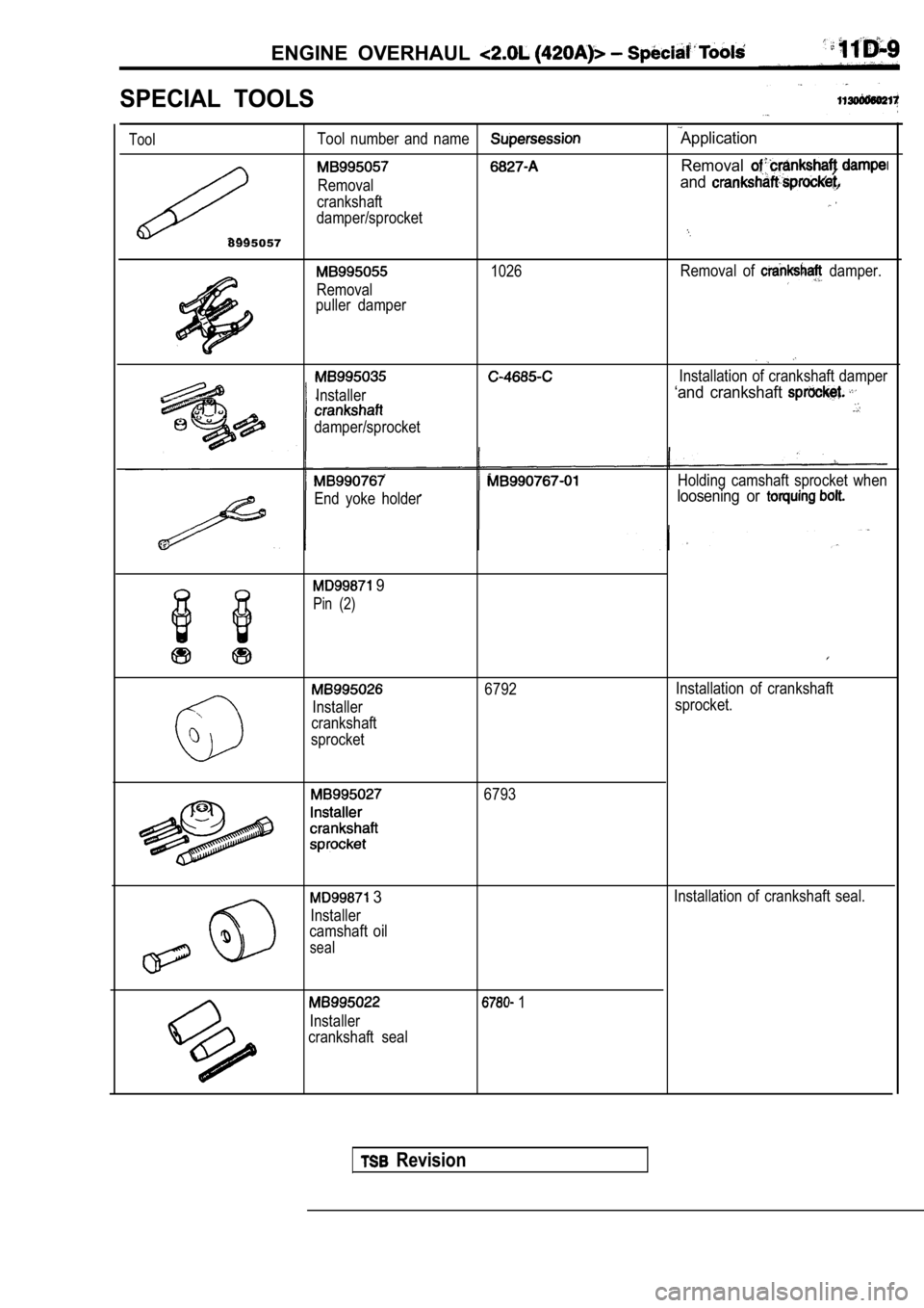
SPECIAL TOOLS
ToolTool number and nameApplication
Removal
Removaland
crankshaft
damper/sprocket
8995057
1026Removal of damper.
Removal
puller damper
Installer
damper/sprocket
Installation of crankshaft damper
‘and crankshaft
End yoke holder
Holding camshaft sprocket when
loosening or
9
Pin (2)
6792 Installation of crankshaft
Installer sprocket.
crankshaft
sprocket
6793
3Installation of crankshaft seal.
Installer
camshaft oil
seal
Installer
crankshaft seal
1
Revision
Page 216 of 2103
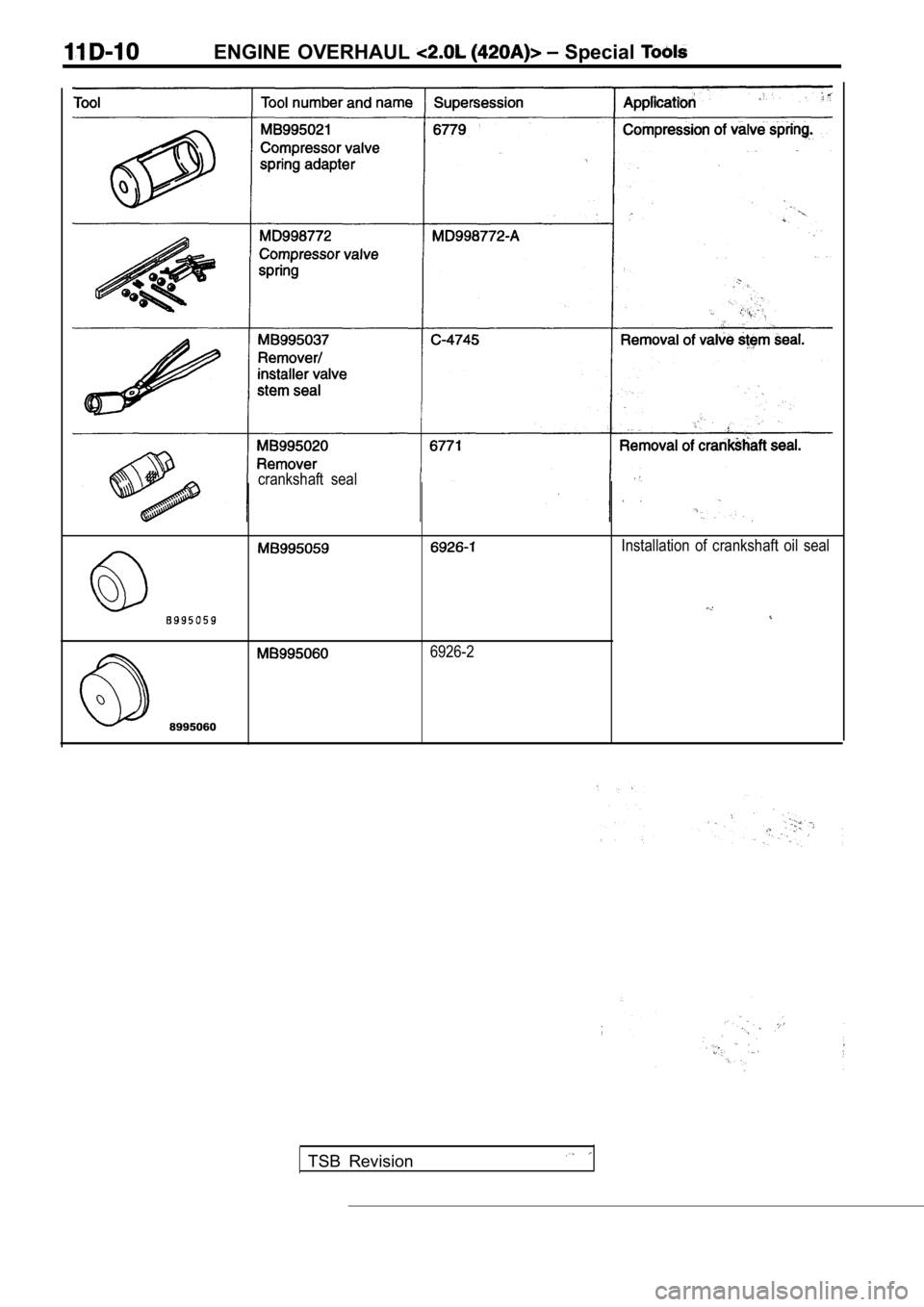
ENGINE OVERHAUL Special
crankshaft seal
Installation of crankshaft oil seal
6926-2
8995060
TSB Revision
Page 217 of 2103
E N G I N E O V E R H A U L G e n e r a t o r
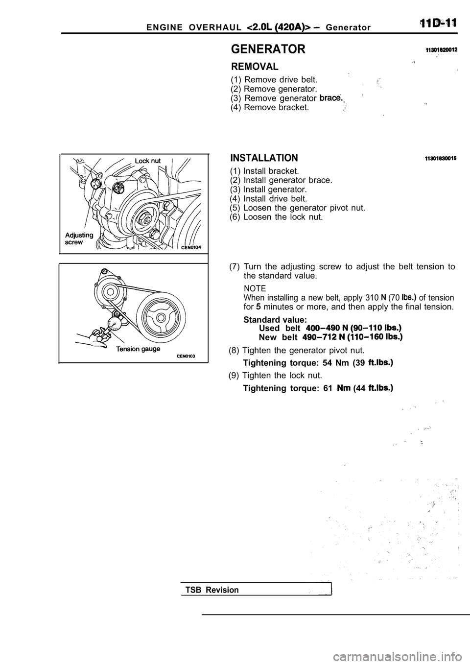
GENERATOR
REMOVAL
(1) Remove drive belt.
(2) Remove generator.
(3) Remove generator
(4) Remove bracket.
INSTALLATION
(1) Install bracket.
(2) Install generator brace.
(3) Install generator.
(4) Install drive belt.
(5) Loosen the generator pivot nut.
(6) Loosen the lock nut.
(7) Turn the adjusting screw to adjust the belt ten sion to
the standard value.
NOTE
When installing a new belt, apply 310 (70 of tension
for minutes or more, and then apply the final tension.
Standard value: Used belt
New belt
(8) Tighten the generator pivot nut.
Tightening torque: 54 Nm (39
(9) Tighten the lock nut.
Tightening torque: 61
(44
TSB Revision
Page 218 of 2103
ENGINE OVERHAUL
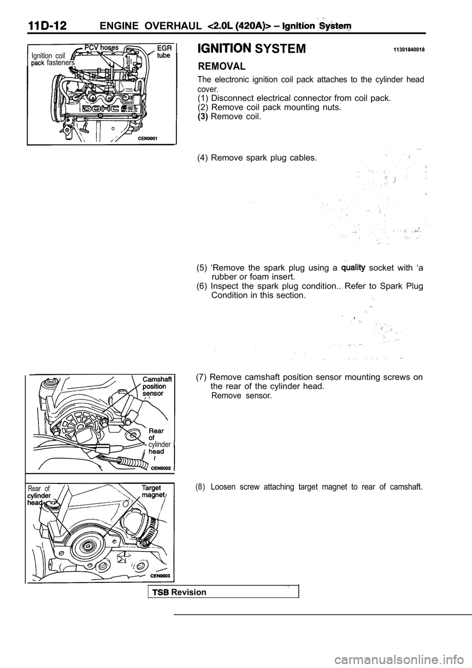
SYSTEM11301840018Ignition coil fasteners
cylinder
Rear of
REMOVAL
The electronic ignition coil pack attaches to the cylinder head
cover.
(1) Disconnect electrical connector from coil pack.
(2) Remove coil pack mounting nuts.
(3)Remove coil.
(4) Remove spark plug cables.
(5) ‘Remove the spark plug using a
socket with ‘a
rubber or foam insert.
(6) Inspect the spark plug condition.. Refer to Spa rk Plug
Condition in this section.
,
(7) Remove camshaft position sensor mounting screws on
the rear of the cylinder head.
Remove sensor.
(8)Loosen screw attaching target magnet to rear of cam shaft.
Revision
Page 219 of 2103
ENGINE OVERHAUL Ignition
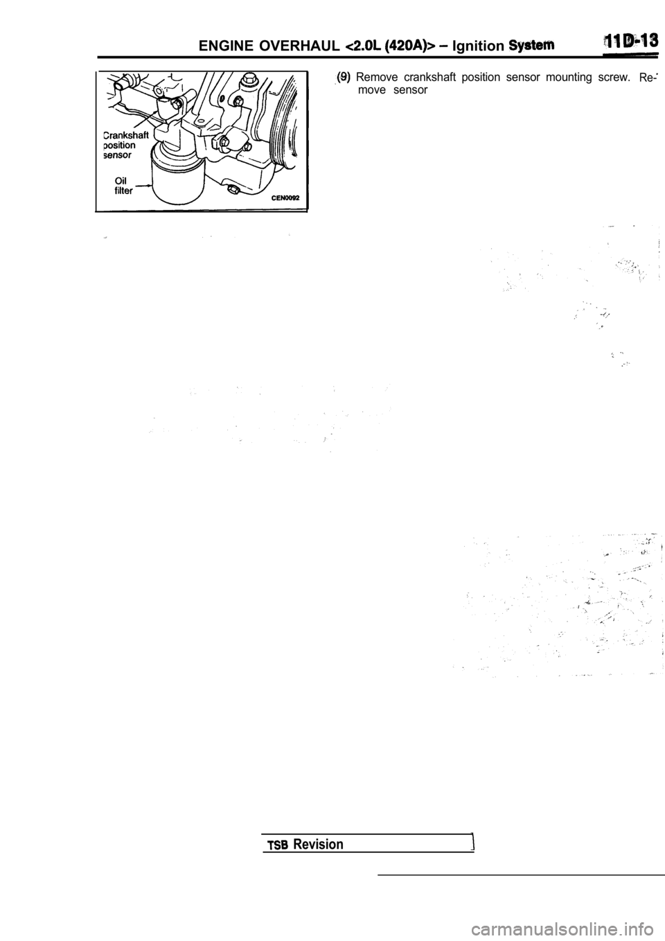
Remove crankshaft position sensor mounting screw.Re-
move sensor
Revision
Page 220 of 2103
ENGINE OVERHAUL
.
INSTALLATION
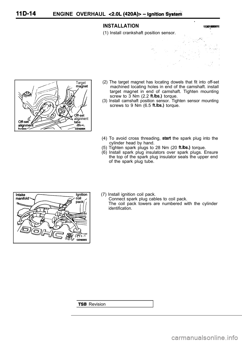
(1) Install crankshaft position sensor.
Target
alignment
(2) The target magnet has locating dowels that fit into off-set
machined locating holes in end of the camshaft. ins tall
target magnet in end of camshaft. Tighten mounting
screw to 3 Nm (2.2
torque.
(3) Install camshaft position sensor. Tighten senso r mounting
screws to 9 Nm (6.5 torque.
(4) To avoid cross threading,
the spark plug into the
cylinder head by hand.
(5) Tighten spark plugs to 28 Nm (20
torque.
(6) Install spark plug insulators over spark plugs. Ensure
the top of the spark plug insulator seals the upper end
of the spark plug tube.
(7) Install ignition coil pack. Connect spark plug cables to coil pack.
The coil pack towers are numbered with the cylinder
identification.
Revision