MITSUBISHI SPYDER 1990 Service Repair Manual
Manufacturer: MITSUBISHI, Model Year: 1990, Model line: SPYDER, Model: MITSUBISHI SPYDER 1990Pages: 2103, PDF Size: 68.98 MB
Page 171 of 2103
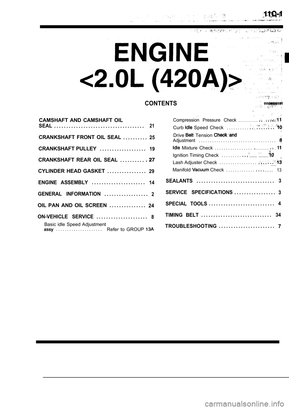
CONTENTS
CAMSHAFT AND CAMSHAFT OIL
SEAL. . . . . . . . . . . . . . . . . . . . . . . . . . . . . . . . . . . . .21
CRANKSHAFT FRONT OIL SEAL. . . . . . . . . .25
CRANKSHAFT PULLEY. . . . . . . . . . . . . . . . . . .19
CRANKSHAFT REAR OIL SEAL
. . . . . . . . . .
CYLINDER HEAD GASKET. . . . . . . . . . . . . . . .29
ENGINE ASSEMBLY. . . . . . . . . . . . . . . . . . . . . .14
GENERAL INFORMATION. . . . . . . . . . . . . . . . . .2
OIL PAN AND OIL SCREEN . . . . . . . . . . . . . . .24
ON-VEHICLE SERVICE
. . . . . . . . . . . . . . . . . . . . .8
Basic idle Speed Adjustment. . . . . . . . . . . . . . . . . . . . . Refer to GROUP
Compression Pressure Check. . . . . . . . . ..
Curb Speed Check . . . . . . . . . ...
Drive Tension
Adjustment. . . . . . . . . . . . . . . . . . . . . . . . . . . . . . . . . . .
Mixture Check . . . . . . . . . . . . . . . . .. . . . . . ..
Ignition Timing Check. . . . . . . . .....................
Lash Adjuster Check . . . . . . . . . . . . . . . . .
......
. . . . .
Manifold Check . . . . . . . . . . . . .13
SEALANTS. . . . . . . . . . . . . . . . . . . . . . . . . . . . . . . .3
SERVICE SPECIFICATIONS. . . . . . . . . . . . . . . . .3
SPECIAL TOOLS. . . . . . . . . . . . . . . . . . . . . . . . . . .4
TIMING BELT. . . . . . . . . . . . . . . . . . . . . . . . . . . . .34
TROUBLESHOOTING. . . . . . . . . . . . . . . . . . . . . . .
7
Page 172 of 2103
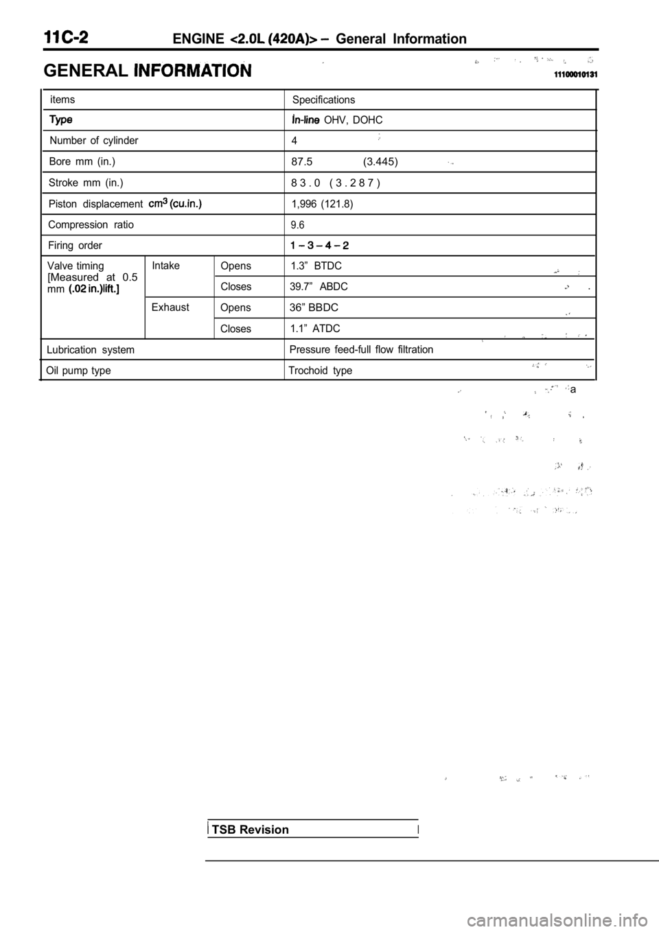
ENGINE General Information
GENERAL
itemsSpecifications
OHV, DOHC
Number of cylinder 4
Bore mm (in.)87.5 (3.445)
Stroke mm (in.)8 3 . 0 ( 3 . 2 8 7 )
Piston displacement 1,996 (121.8)
Compression ratio
9.6
Firing order
Valve timing Intake
Opens 1.3” BTDC
[Measured at 0.5
mmCloses 39.7” ABDC .
Exhaust Opens36” BBDC
Closes 1.1” ATDC
Lubrication system Pressure feed-full flow filtration
Oil pump type Trochoid type
a
TSB RevisionI
Page 173 of 2103
ENGINE ‘Service
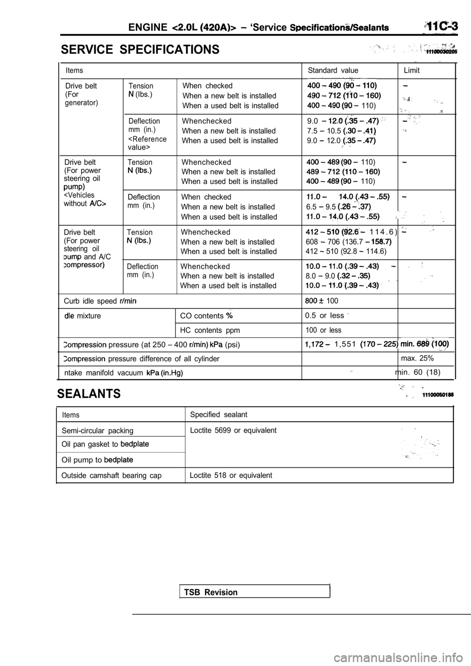
SERVICE SPECIFICATIONS
Items
Drive belt
(For
generator)
Standard value Limit
TensionWhen checked
(Ibs.) When a new belt is installed
When a used belt is installed
110)
DeflectionWhenchecked9.0
mm (in.)When a new belt is installed 7.5 10.5
Drive beltTensionWhenchecked
(For power
When a new belt is installed
steering oil
When a used belt is installed
mm (in.)When a new belt is installed
When a used belt is installed
Drive belt
TensionWhenchecked
(For power
When a new belt is installedsteering oil
and A/C When a used belt is installed
DeflectionWhenchecked
mm (in.)When a new belt is installed
When a used belt is installed
Curb idle speed
mixtureCO contents
HC contents ppm
pressure (at 250 400 (psi)
pressure difference of all cylinder
ntake manifold vacuum
110)
110)
6.5 9.5
1 1 4 . 6 )
608 706 (136.7
412 510 (92.8 114.6)
8.0 9.0
100
0.5 or less
100 or less
1 , 5 5 1
max. 25%
min. 60 (18)
SEALANTS
Items
Semi-circular packing
Oil pan gasket to
Oil pump to
Outside camshaft bearing cap Specified sealant
Loctite 5699 or equivalent
Loctite 518 or equivalent
TSB Revision
Page 174 of 2103
ENGINE Special
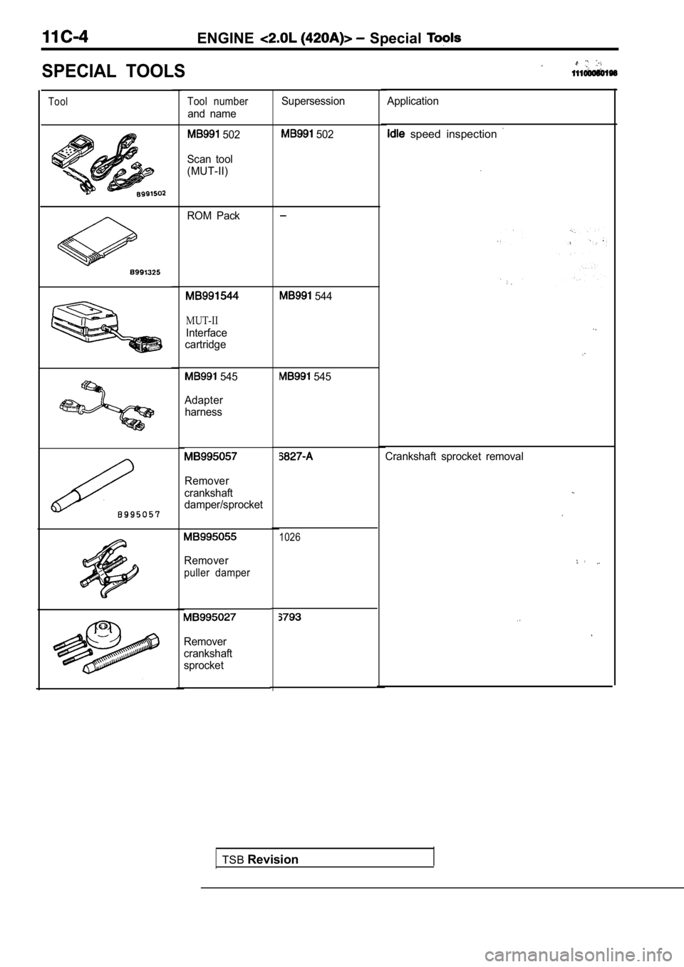
SPECIAL TOOLS
ToolTool number
and name
502
Scan tool
(MUT-II)
ROM Pack
MUT-II
Interface
cartridge
545
Adapter harness
Remover
crankshaft
damper/sprocket
Remover
puller damper
Remover
crankshaft
sprocket Supersession
502
544
545
TSB
Revision
1026
Application
speed inspection
Crankshaft sprocket removal
Page 175 of 2103
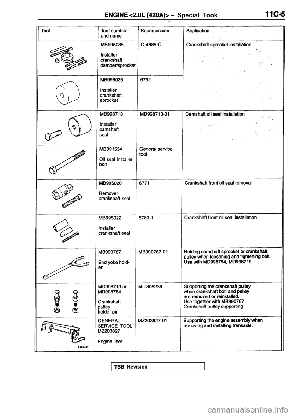
Special Took
Oil seal installer
seal
SERVICE TOOL
Revision
Page 176 of 2103
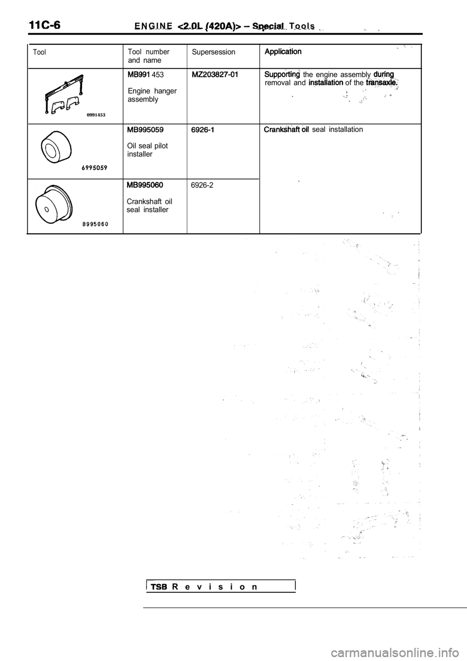
E N G I N E T o o l s
ToolTool numberSupersession
and name
0991453
453
Engine hanger
assembly the engine assembly
removal and of the ,..
seal installation
Oil seal pilot installer
6995059
6926-2
Crankshaft oil
seal installer
R e v i s i o n
Page 177 of 2103
ENGINE Troubleshooting,
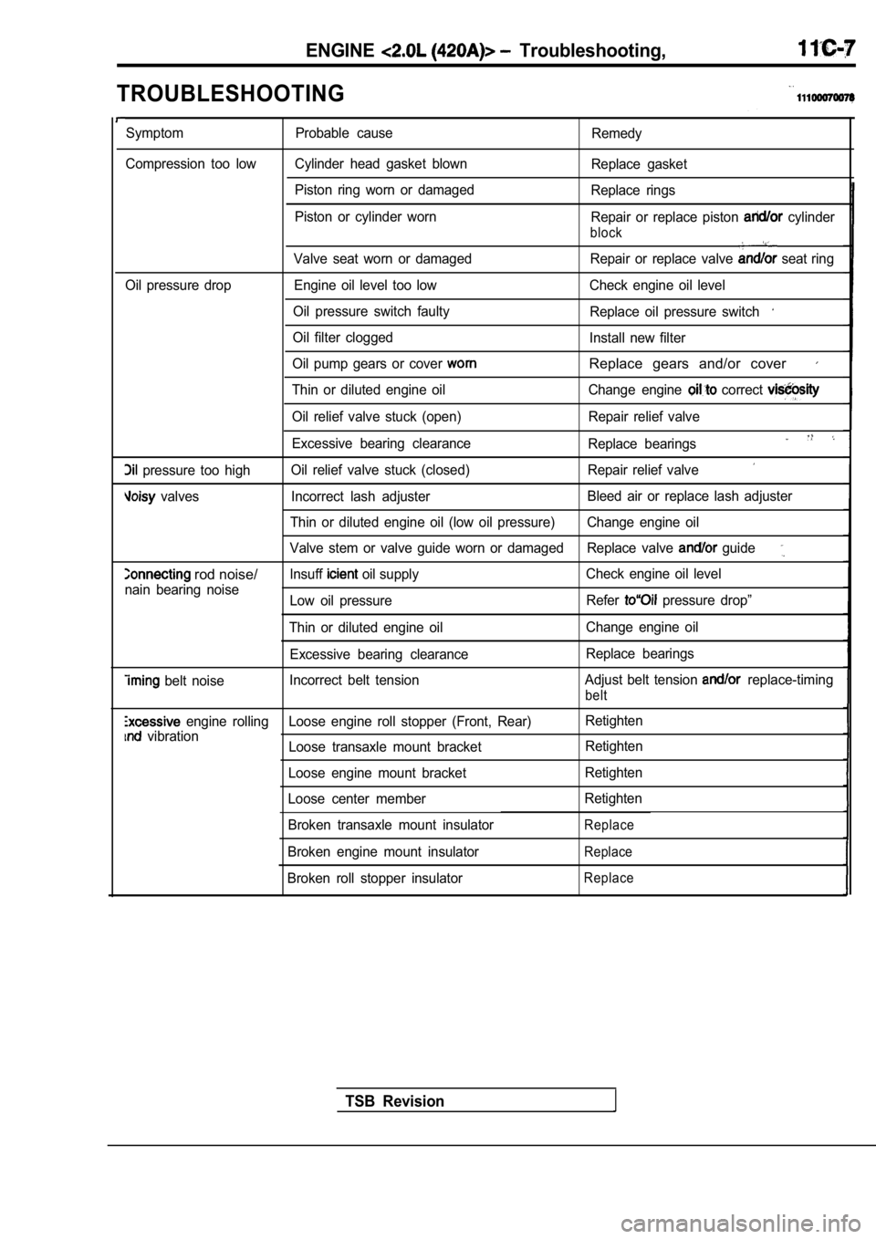
TROUBLESHOOTING
Symptom Probable causeRemedy
Compression too low Cylinder head gasket blown Replace gasket
Piston ring worn or damaged Replace rings
Piston or cylinder worn Repair or replace piston
cylinder
block
Valve seat worn or damaged Repair or replace valve seat ring
Oil pressure drop Engine oil level too low Check engi ne oil level
Oil pressure switch faulty Replace oil pressure switch
Oil filter clogged
Install new filter
Oil pump gears or cover
Replace gears and/or cover
Thin or diluted engine oil Change engine correct
Oil relief valve stuck (open) Repair relief valve
Excessive bearing clearance Replace bearings
pressure too highOil relief valve stuck (closed) Repair relief valve
valves Incorrect lash adjuster Bleed air or replace lash adjuster
Thin or diluted engine oil (low oil pressure) Change engine oil
Valve stem or valve guide worn or damaged Replace va lve
guide
rod noise/lnsuff oil supplyCheck engine oil level
nain bearing noise Low oil pressure Refer
pressure drop”
Thin or diluted engine oil Change engine oil
Excessive bearing clearance Replace bearings
belt noiseIncorrect belt tension
Adjust belt tension replace-timing
belt
engine rolling Loose engine roll stopper (Front, Re
ar)Retighten
vibration
Loose transaxle mount bracket Retighten
Loose engine mount bracket Retighten
Loose center member Retighten
Broken transaxle mount insulator
Replace
Broken engine mount insulatorReplace
Broken roll stopper insulatorReplace
TSB Revision
Page 178 of 2103
Crankshaft
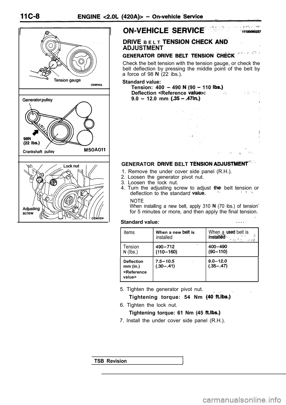
B E L T
ADJUSTMENT
Check the belt tension with the tension gauge, or check the
belt deflection by pressing the middle point of the belt by
a force of 98
(22 ibs.).
Standard value: Tension: 400
490 (90 110
Deflection
GENERATOR BELT
1. Remove the under cover side panel (R.H.).
2. Loosen the generator pivot nut.
3. Loosen the lock nut.
4. Turn the adjusting screw to adjust
belt tension or
deflection to the standard
NOTE
When installing a new belt, apply 310
(70 ibs.) of tension’
for 5 minutes or more, and then apply the final ten sion.
Standard value:. . . .
items
Tension
(Ibs.)
When a new is
installed
When a belt is
Deflection
mm (in.)
5. Tighten the generator pivot nut.
Tightening torque: 54 Nm
6. Tighten the lock nut.Tightening torque: 61 Nm (45
7. Install the under cover side panel (R.H.).
TSB Revision
Page 179 of 2103
ENGINE On-vehicle
Power
Powersteering oilpump pulleyTension
pulley
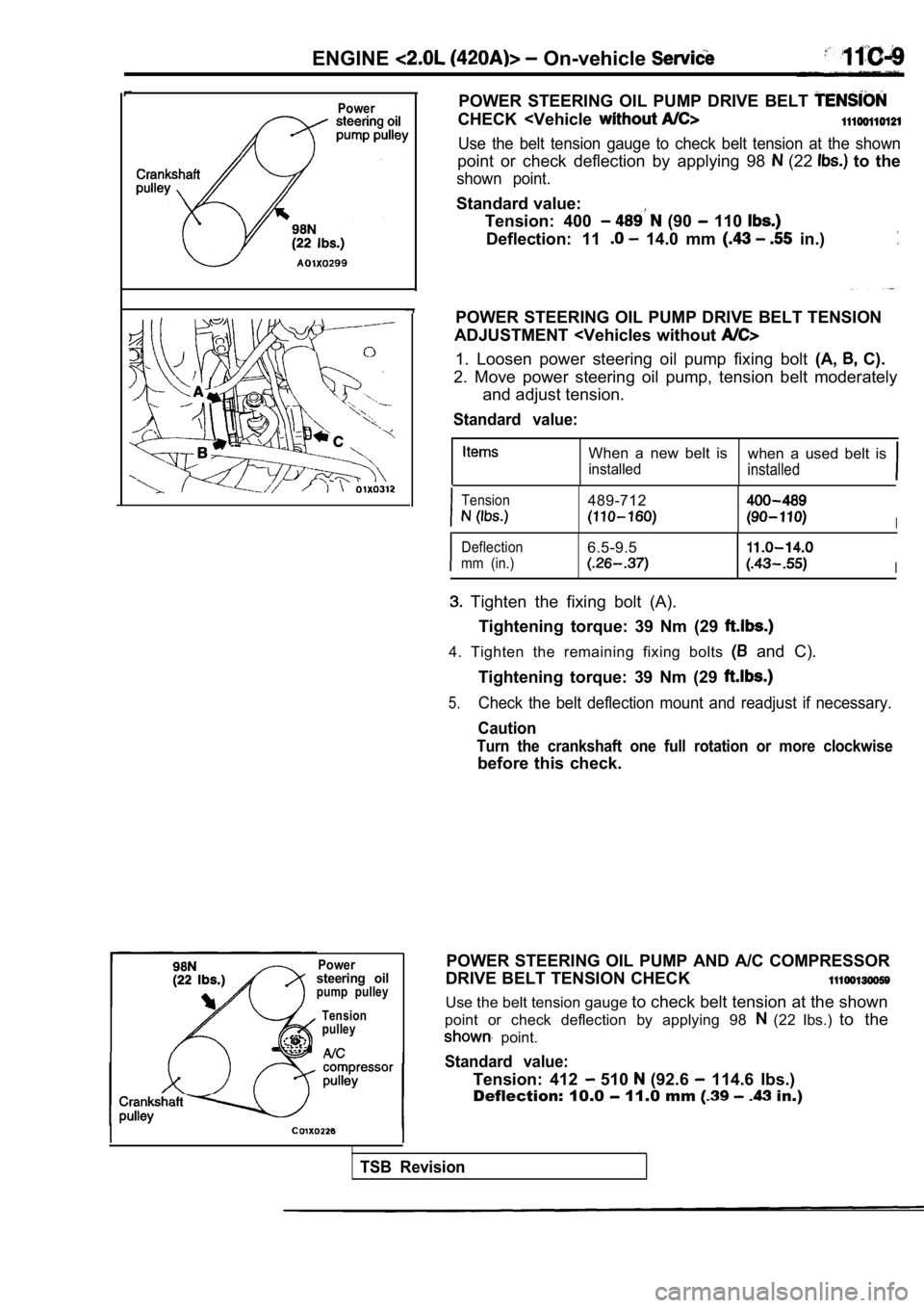
POWER STEERING OIL PUMP DRIVE BELT
CHECK
point or check deflection by applying 98 (22 to the
shown point.
Standard value:
Tension: 400
(90 110
Deflection: 11 14.0 mm in.)
POWER STEERING OIL PUMP DRIVE BELT TENSION
ADJUSTMENT
2. Move power steering oil pump, tension belt moder ately
and adjust tension.
Standard value:
When a new belt is when a used belt is
installedinstalled
Tension489-712
I
Deflection6.5-9.5
mm (in.)I
Tighten the fixing bolt (A).
Tightening torque: 39 Nm (29
4. Tighten the remaining fixing bolts and C).
Tightening torque: 39 Nm (29
5.Check the belt deflection mount and readjust if nec essary.
Caution
Turn the crankshaft one full rotation or more clock wise
before this check.
POWER STEERING OIL PUMP AND A/C COMPRESSOR
DRIVE BELT TENSION CHECK
Use the belt tension gauge to check belt tension at the shown
point or check deflection by applying 98
(22 Ibs.) to the
point.
Standard value:
Tension: 412 510 (92.6 114.6 Ibs.)
Deflection: 10.0
11.0 mm in.)
TSB Revision
Page 180 of 2103
ENGINE On-vehicle Service
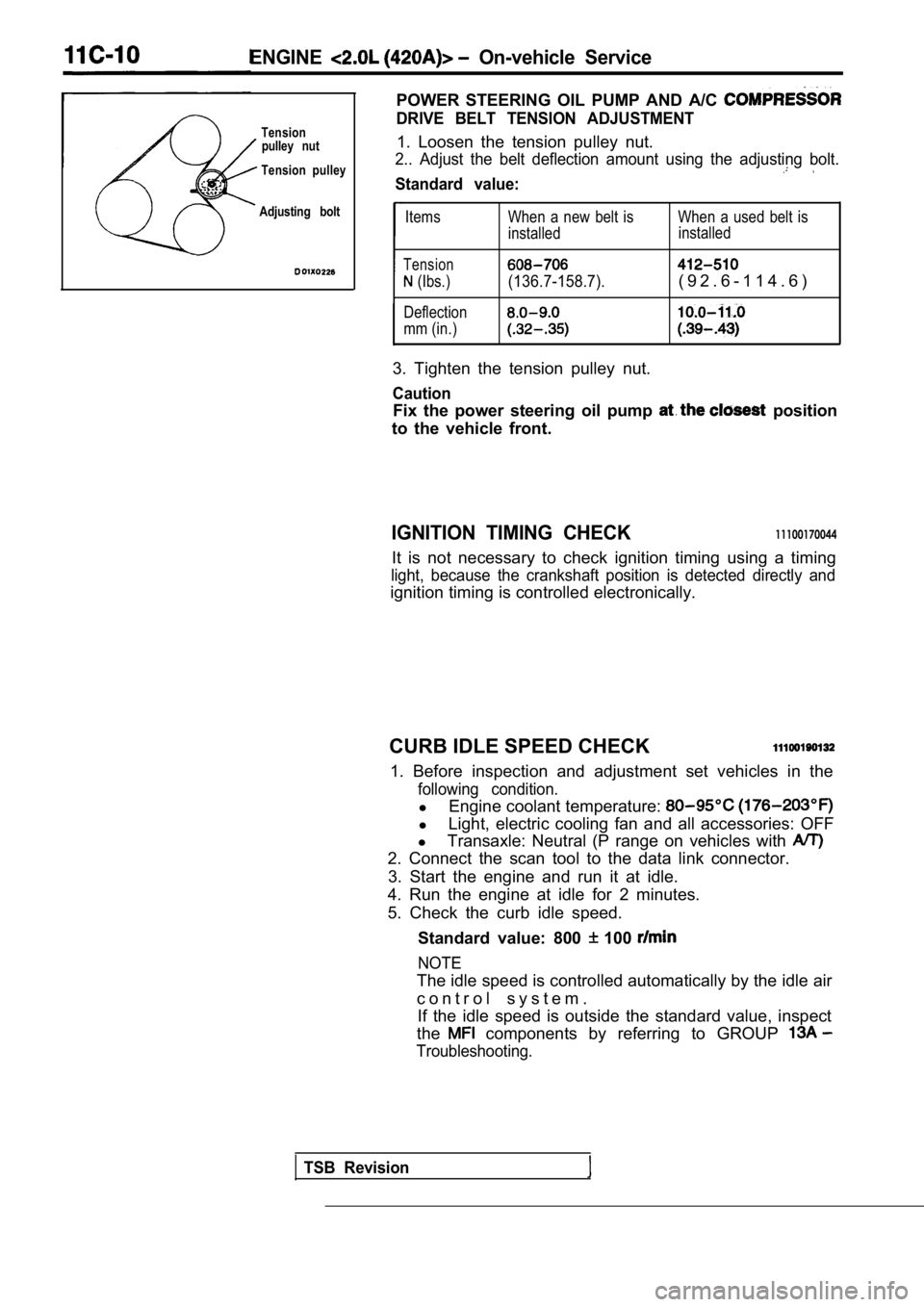
POWER STEERING OIL PUMP AND A/C
DRIVE BELT TENSION ADJUSTMENTTensionpulley nut1. Loosen the tension pulley nut.
Tension pulley2.. Adjust the belt deflection amount using the adj usting bolt.
Standard value:
Adjusting boltItems
Tension
(Ibs.)
Deflection
mm (in.) When a new belt is When a used belt is
installed
installed(136.7-158.7).( 9 2 . 6 - 1 1 4 . 6 )
3. Tighten the tension pulley nut.
Caution
Fix the power steering oil pump position
to the vehicle front.
IGNITION TIMING CHECK11100170044
It is not necessary to check ignition timing using a timing
light, because the crankshaft position is detected directly and
ignition timing is controlled electronically.
CURB IDLE SPEED CHECK
1. Before inspection and adjustment set vehicles in the
following condition.
lEngine coolant temperature:
lLight, electric cooling fan and all accessories: OF F
l Transaxle: Neutral (P range on vehicles with
2. Connect the scan tool to the data link connector .
3. Start the engine and run it at idle.
4. Run the engine at idle for 2 minutes.
5. Check the curb idle speed.
Standard value: 800
100
NOTE
The idle speed is controlled automatically by the i dle air
c o n t r o l s y s t e m . If the idle speed is outside the standard value, in spect
the
components by referring to GROUP
Troubleshooting.
TSB Revision