NISSAN ALMERA N15 1995 Service Manual
Manufacturer: NISSAN, Model Year: 1995, Model line: ALMERA N15, Model: NISSAN ALMERA N15 1995Pages: 1701, PDF Size: 82.27 MB
Page 441 of 1701
HEADLAMP-Daytime LightSystem -
System Description
The headlamp systemonvehicles forNorth Europe contains adaytime lightunit.Theunitactivates the
following whenever theengine isrunning withthelighting switchinthe OFF position:
• Low beam headlamps
• Clearance, license,tailand illumination lamps
Power issupplied atall times
• through 15Afuse (No.
@ill,
located inthe fusible linkand fuse box)
• todaytime lightunitterminal @and
• tolighting switchterminal
@.
Power isalso supplied atall times
• through 15Afuse (No.~,located inthe fusible linkand fuse box)
• todaytime lightunitterminal
CID
and
• tolighting switchterminal
CID.
Power isalso supplied atall times
• through 10Afuse (No.~,located inthe fusible linkand fuse box)
• todaytime lightunitterminal
CD
and
• tolighting switchterminal @.
With theignition switchinthe ONorSTART position, powerissupplied
• through 10Afuse (No.~,located inthe fuse block)
• todaytime lightunitterminal (]).
With theignition switchinthe START position, powerissupplied
• through 7.5Afuse(No.
l2~,
located inthe fuse block)
• todaytime lightunitterminal @.
Ground issupplied todaytime lightunitterminal @through bodygrounds
@
and@D.
HEADLAMP OPERATION (Daytimelightcancel operation)
Power issupplied atall times
• through 10Afuse (No.~,located inthe fuse andfusible linkbox)
• tolighting switchterminal
@.
When thelighting switchisturned tothe 1stor2nd position
• through lightingswitchterminal @,
• todaytime lightunitterminal
@.
Then daytime lightwillbecanceled. Andthelighting systemoperation willbethe same asnodaytime
light system.
DAYTIME LIGHTOPERATION
With theengine running andthelighting switchinthe OFF position, powerissupplied
• from alternator terminal
CI>
• todaytime lightunitterminal
@
• todaytime lightunitterminal @
• through daytime lightunitterminal
CID
• toterminal
@)
ofLH headlamp
• todaytime lightunitterminal
CID
• through daytime lightunitterminal @
• toterminal
@)
ofRH headlamp
• todaytime lightunitterminal
CD
• through daytime lightunitterminal
@)
• totail lamp andillumination.
Ground issupplied toterminal
@
ofeach headlamp throughbodygrounds
@
and@D.
Ground isalso supplied toterminal @ofdaytime lightunitthrough bodygrounds
@
and@D.
EL-69
•
Page 442 of 1701
HEADlAMP-Daytime lightSystem -
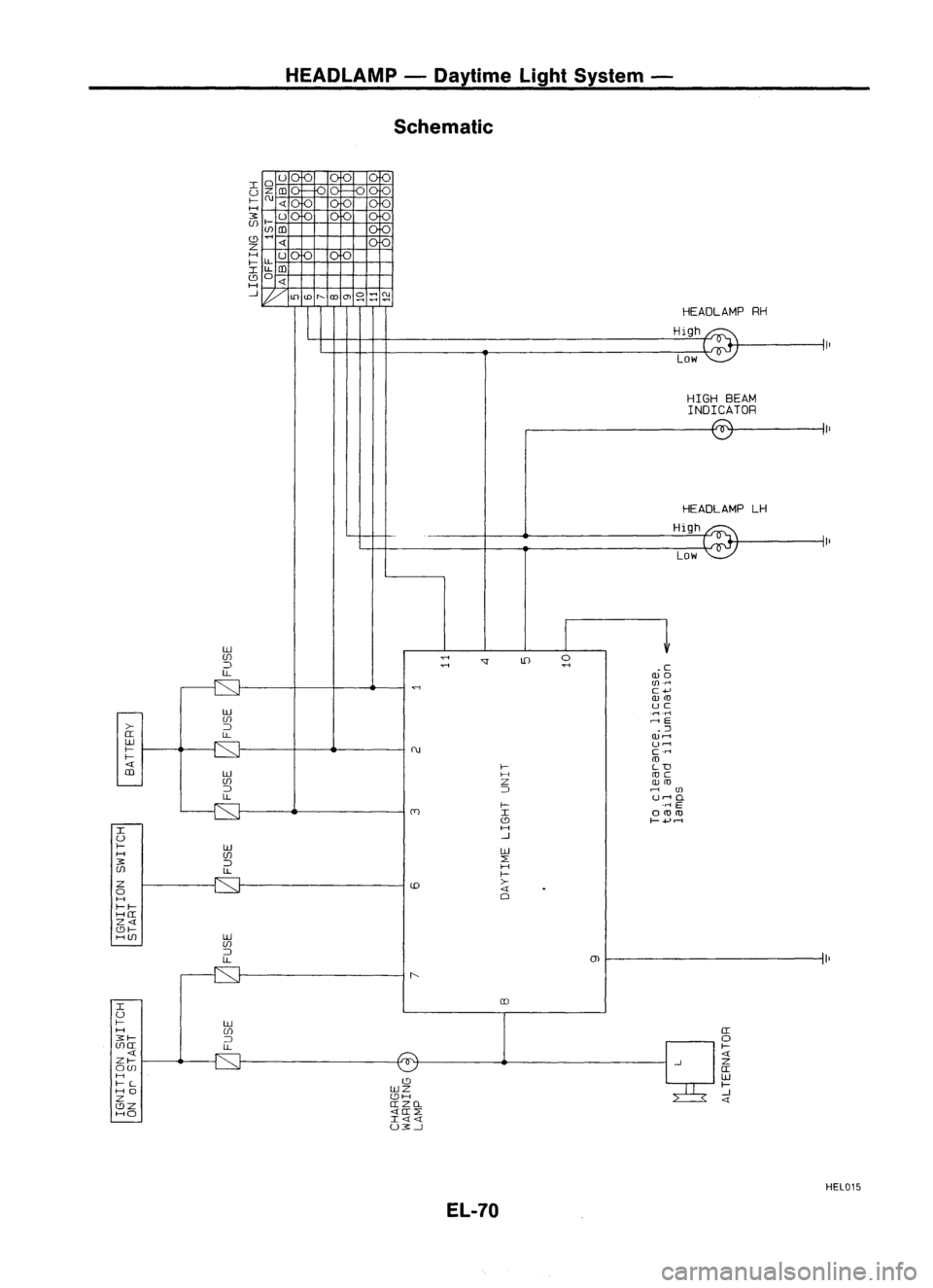
Schematic
HEADLAMPRH
High
Low
HIGH BEAM
INDICATOR
HEADLAMP LH
High
Low
ill
UJ
..,;
'J
Ul
0
::J
..,;
..,;
.c
LL
WO
(fl .....
C+'
w
ill
.
.-1.rl
UJ
,...,E
>-
::J
.::J
IT
LL
W"'"
ill
u.-.
I-
c.....
I-
<0
« I-LD
m
ill
H
UJ Z
w
::J ::J
,...,
(fl
LL
u,...,
0.
l-
.....
E
I OlUlU
(9
I-+,"'"
I H
U --l
I-
IJJ
IJJ
H UJ
::E
3:
::J
UJ
LL
H
I-
Z
>-
0
«
H
0
1-1-
HIT
Z«
(91-
HUJ IJJ
UJ
::J
LL
01
I
aJ
U
I-
ill
H UJ IT
3:1-
::J
0
UJIT
LL
I-
« «
ZI- Z
OUJ IT
H (9 IJJ
I-L
I-
HO IJJZ
--l
Z (9H
«
(9Z ITZCL
HO «IT::E
I««
U3:--l
El-70
HEL015
Page 443 of 1701
HEADlAMP-Daytime LightSystem -
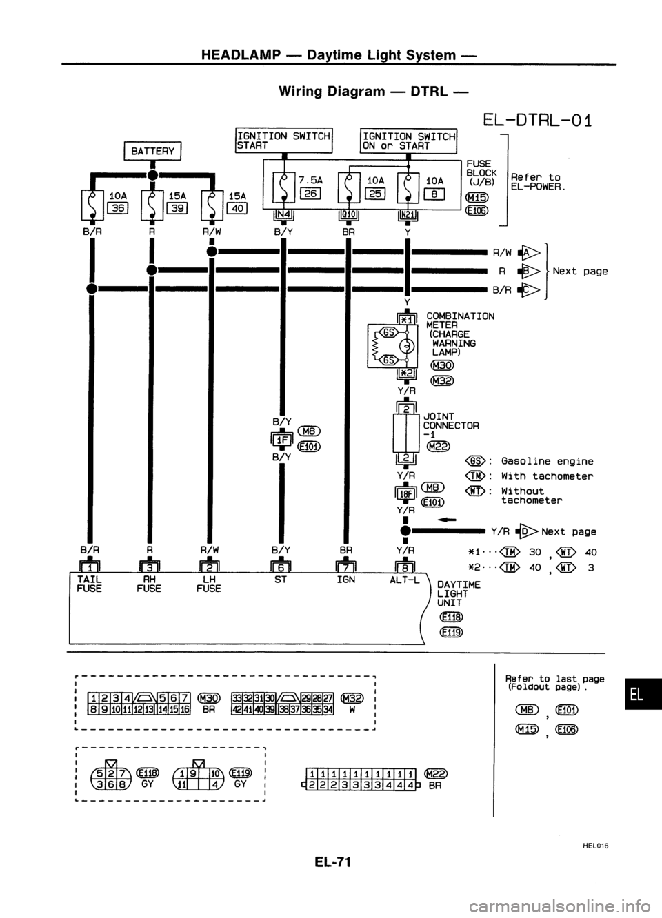
Wiring Diagram -DTRl -
•
Refer
to
EL-POWER.
Gasoline engine
With tachometer
Without
tachometer
EL-DTRL-01
FUSE
BLOCK
(JIB)
(£106)
COMBINATION
METER
(CHARGEWARNING
LAMP)
~
~
Refertolast page
(Foldout page).
10A
IT]
~
Y
1
R~W:} Nextpage
----B/R~
Y
~
~
IR
rn~
I
~g~~~CTOR
-1
@
~ @:
IR
@:
II~IQID
@:
T-'
(EiQD
IR
.
~
.'----- YIR
-{9>
Next page
•
Y
IR
*1
@
30
@
40
m
*2
@
40
'@
3
,
ALT -L DAYTIME
LIGHT
UNIT
(El1B)
BR
m
IGN
B/Y
m ST
•
•
GS
GS
Y
B/Y
IfWlJCMID
11:1~
B/Y
Y
1
Y
R/W
m
LH
FUSE
R
m
RH
FUSE
I
BATTERY
I
rr::-J;::-'Jl
15A
~I~
W~I
~1401
B/R RR/W
I
!
•
B/R
m
TAIL
FUSE
L ~
~---------------------,
I I
: ~ (~ITB)~
(E119):
I~GY~GYI
I I
L ~
~~
~ BR
HEL016
El-71
Page 444 of 1701
HEADLAMP-Daytime LightSystem -
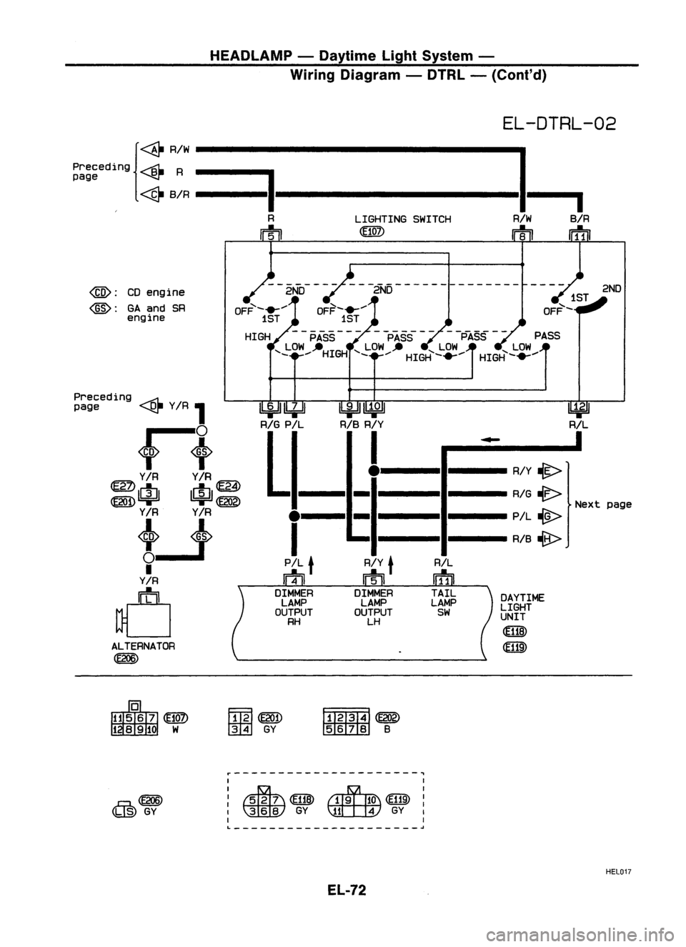
Wiring Diagram -DTRL -(Cont'd)
EL-DTRL-02
{~ RIW
I
Preceding
----Bt-
R
==I
page ~
~ BIR --------------
I
R LIGHTINGSWITCH RIWBIR
m
Irf1iI
@:
CDengine
@:
GAand SR
engine
--2NO---
--2ND--------------
OFF- .......
1ST
HIGH PASS PASS-
-PASS --
PASS
'- LOW --HIGH '-LOW __ '-LOW '-LOW
_.... _....HIGH-....... HIGH-.......
2ND
ext page
~
RIL
DAYTIME
LIGHT
UNIT
~
(ffiID
RIL
wf1]
TAIL
LAMP
SW
I
.....
I
R/Y
lit>
RIG ~
N
PIL
-@>
RIB ~
RIY
t
m
DIMMER LAMP
OUTPUT
LH
e--II-
I
PIL
t
m
DIMMER LAMP
OUTPUT
RH
~~
1biJJ~
RIG
PIL RIBRIY
L._._e
ALTERNATOR
~
Preceding
.....-;::;1.
page ~YIR
1
~t
YIR YIR
~ IctJl 1r1J1~
@ID=r =r~
Y/R Y/R
tJ
I
Y/R
d
Ffm~
ffi
GY
~~
~B
r---------------------,
@lID
(~) GY
I
I
: ~ @ID~
I ~
GY
\llLt:W
GY
I
I I
L
~
HEl017
EL-72
Page 445 of 1701
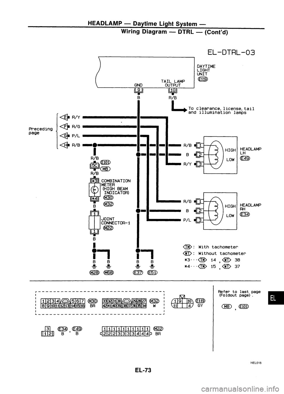
HEADLAMP-Daytime LightSystem -
Wiring Diagram -DTRL -(Cont'd)
EL-DTRL-03
•
HIGH
HEADLAMP
LH
LOW
m
HIGH HEADLAMP
RH
LOW ~
Refer tolast page
(Foldout page).
DAYTIME
LIGHT
UNIT
(ffiID
RIB
!(J
BQ
R/Y
JD
RIG
!(J
sQ
PIL
JD
@:
With tachometer
@:
Without tachometer
*3"'@ 14
@
38
,
*4"'@15 @37
,
~(ffiID
~GY
TAIL
LAMP
OUTPUT
~
RIB
~ Toclearance. license.tail
and illumination lamps
GND
~ B
,..,
B S
~ ~
@~
,..,
B B
~ ~
(M28) ~
.
-.
-
-
-
-
I
.-
-
-
-
RIB
1r$J1~
@
RIB
I it"S INATION
METER
(HIGH BEAM
INDICATOR)
1*':' ~
B
@
W
.-
JOINT
CONNECTOR-1
1bjJ~
B
I
~
R/Y
<&
RIG
~ PIL
Preceding
page
~~m
[]]JgJ]
B'8
I1IillIillIITil
~
~ SR
HEL018
EL-73
Page 446 of 1701
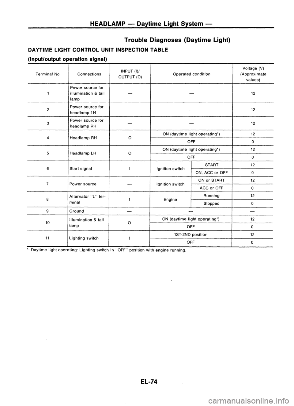
HEADLAMP-Daytime LightSystem -
Trouble Diagnoses (DaytimeLight)
DAYTIME LIGHTCONTROL UNITINSPECTION TABLE
(Input/output operationsignal)
INPUT
(1)/
Voltage
(V)
Terminal No. Connections
OUTPUT
(0)
Operated
condition (Approximate
values)
Power source for
1 illumination
&
tail
- -
12
lamp
2 Power
source for
12
- -
head lamp LH
3
Power
source for
12
-
-
head lamp RH
ON(daytime lightoperating')
12
4
HeadlampRH
0
OFF 0
ON (daytime lightoperating') 12
5
HeadlampLH
0
OFF 0
START 12
6
Startsignal
I
Ignitionswitch
ON,ACC orOFF
0
ON orSTART
12
7
Powersource
-
Ignition
switch
ACCorOFF
0
Alternator "L"ter- Running
12
8
I
Engine
minal Stopped0
9 Ground
- - -
Illumination
&
tail ON
(daytime lightoperating')
12
10 lamp
0
OFF 0
1ST.2ND position
12
11 Lightingswitch
I
OFF 0
': Daytime lightoperating: Lightingswitchin"OFF" position withengine running.
EL-74
Page 447 of 1701
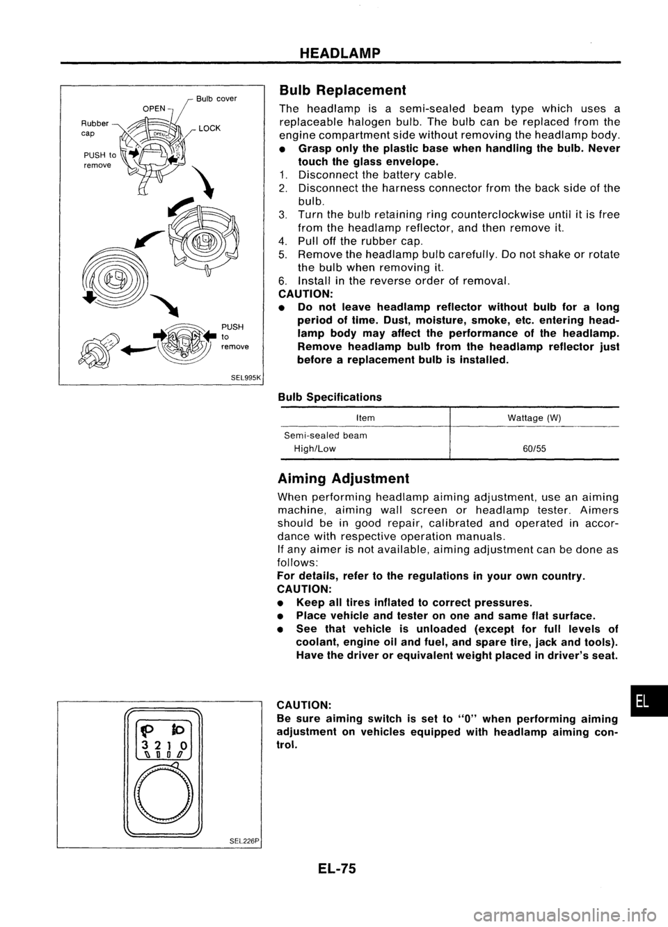
Bulbcover
SEL995K HEADLAMP
Bulb Replacement
The headlamp isasemi-sealed beamtypewhich usesa
replaceable halogenbulb.Thebulb canbereplaced fromthe
engine compartment sidewithout removing theheadlamp body.
• Grasp onlytheplastic basewhen handling thebulb. Never
touch theglass envelope.
1. Disconnect thebattery cable.
2. Disconnect theharness connector fromtheback sideofthe
bulb.
3. Turn thebulb retaining ringcounterclockwise until
it
is free
from theheadlamp reflector,andthen remove it.
4. Pull offthe rubber cap.
5. Remove theheadlamp bulbcarefully. Donot shake orrotate
the bulb when removing it.
6. Install inthe reverse orderofremoval.
CAUTION:
• Do not leave headlamp reflector withoutbulbforalong
period oftime. Dust,moisture, smoke,etc.entering head-
lamp bodymayaffect theperformance ofthe head lamp.
Remove headlamp bulbfrom thehead lamp reflector just
before areplacement bulbisinstalled.
Bulb Specifications
Item
Semi-sealed beam
High/Low Wattage
(W)
60/55
f>
to
3 21 0
~ nOD
o
SEL226PAiming
Adjustment
When performing headlamp aiming adjustment, useanaiming
machine, aimingwallscreen orheadlamp tester.Aimers
should beingood repair, calibrated andoperated inaccor-
dance withrespective operationmanuals.
If any aimer isnot available, aimingadjustment canbedone as
follows:
For details, refertothe regulations inyour owncountry.
CAUTION:
• Keep alltires inflated tocorrect pressures.
• Place vehicle andtester onone and same flatsurface.
• See thatvehicle isunloaded (exceptforfull levels of
coolant, engineoiland fuel, andspare tire,jack andtools).
Have thedriver orequivalent weightplaced indriver's seat.
CAUTION: •
Be sure aiming switchisset to
"0"
when performing aiming
adjustment onvehicles equipped withheadlamp aiming con-
trol.
EL-75
Page 448 of 1701
-
Up and down adjusting screw
, \ ,I/
MEL614DHEADLAMP
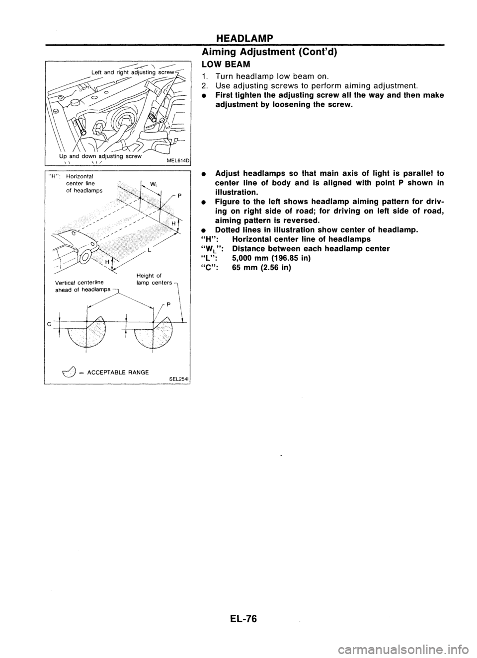
Aiming Adjustment (Cont'd)
LOW BEAM
1. Turn headlamp lowbeam on.
2. Use adjusting screwstoperform aimingadjustment.
• First tighten theadjusting screwallthe way andthen make
adjustment byloosening thescrew.
• Adjust headlamps sothat main axisoflight isparallel to
center lineofbody andisaligned withpoint Pshown in
illustration.
• Figure tothe leftshows headlamp aiming pattern fordriv-
ing onright sideofroad; fordriving onleft side ofroad,
aiming pattern isreversed.
• Dotted linesinillustration showcenter ofhead lamp.
"H":
Horizontal centerlineofheadlamps
"W
L":
Distance betweeneachheadlamp center
"l":
5,000mm(196.85 in)
"e":
65mm (2.56 in)
Height of
lamp centers
I
f
P \
/~
Vertical
centerline
ahead ofheadlamps -
"H":
Horizontal
center line
of headlamps
d
=
ACCEPTABLE RANGE
SEL2541
EL-76
Page 449 of 1701
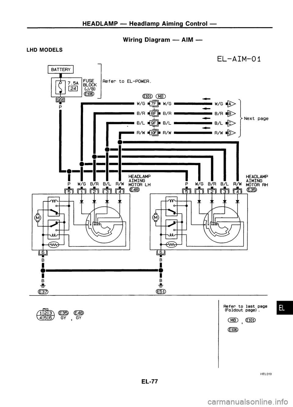
HEADLAMP-Headlamp AimingControl -
Wiring Diagram -AIM -
LHD MODELS
EL-AIM-01
HEADLAMP
AIMING
MOTOR RH
~
.....
WIG~
.....
BIR~
Nextpage
.....
B/L~
.....
RIW
-w>
Refer
toEL-POWER.
FUSE
BLOCK
(JIB)
CE106)
(HOD
WIG ~~ WIG-----
BIR
~b
BIR------
r=B/L~&B/L
I ~
AI.
~1~
AI.-----
.I-.I=.I=.I~:.:-
-==-
-~=I
-I1-"
HEAOLAMP
AIMING
P WIG BIR B/LRIWMOTOR LH PWIG BIRB/L R/W
mmmrnm~ mm~rnm
~
\A:tW
GYGY
Refer
tolast page •
(Foldout page).
HEL019
EL-77
Page 450 of 1701
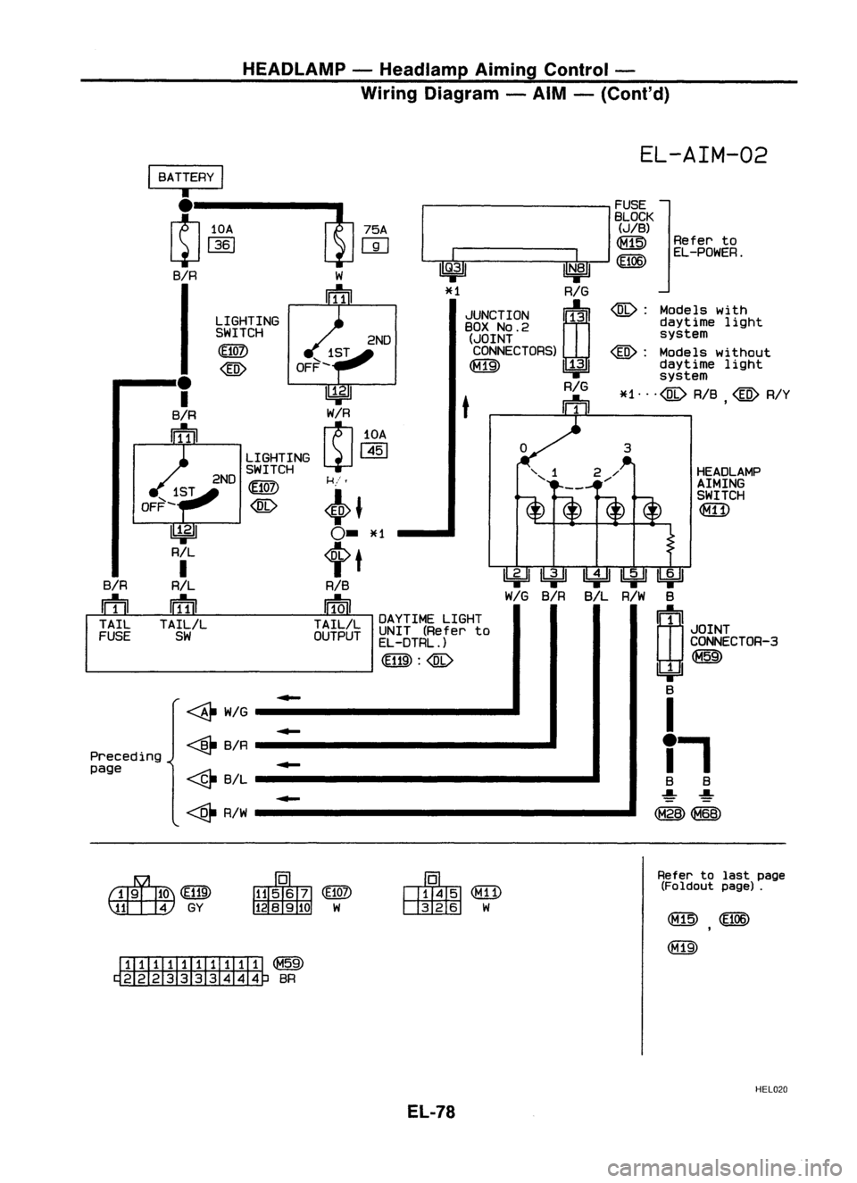
HEADLAMP-Headlamp AimingControl -
Wiring Diagram -AIM -(Cont'd)
HEADLAMPAIMING
SWITCH
~
Refer
to
EL-POWER.
@:
Models with
daytime light
system
@:
Models without
daytime light
system
*1"'@ RIB
@
RIY
,
~~~ B/L R/W B
rn~
I
JOINT
CONNECTOR-3
~
Ibi=U
B
I
i.
B B
~ ~
(M28) ~
~~
WIG
BIR
EL-AIM-02
u@ ~
*1 RIG
JUNCTION
00
BOX
NO.2
(JOINT
CONNECTORS)
RIG
t
rn
---------
FUSE
I
BLOCK
(JIB)
~
(f@
2ND
k:
i,
<6>J
0-
*1
tt
RIB
rm
TAILIL
OUTPUT
-
DAYTIME
LIGHT
UNIT (Refer to
EL-DTRL.)
~:@
-------'
LIGHTING
SWITCH
(E107)
LIGHTING
SWITCH
(E10])
@
2ND
~
RIL
I
R/L
ifill
TAILIL
SW
I
BATTERY
I
•
~-113.0:.1----t!J r~AI
BIR W
~
BIR
rn
TAIL
FUSE
~WIG
-
Preceding ~
BIR
-
page
~B/L
-
~ RIW
~(EU9)
~GY
ITIIIII::ITillT ~
~ BR
Refer
tolast page
(Foldout page).
HEL020
EL-78