NISSAN ALMERA N15 1995 Service Manual
Manufacturer: NISSAN, Model Year: 1995, Model line: ALMERA N15, Model: NISSAN ALMERA N15 1995Pages: 1701, PDF Size: 82.27 MB
Page 431 of 1701
CHARGINGSYSTEM
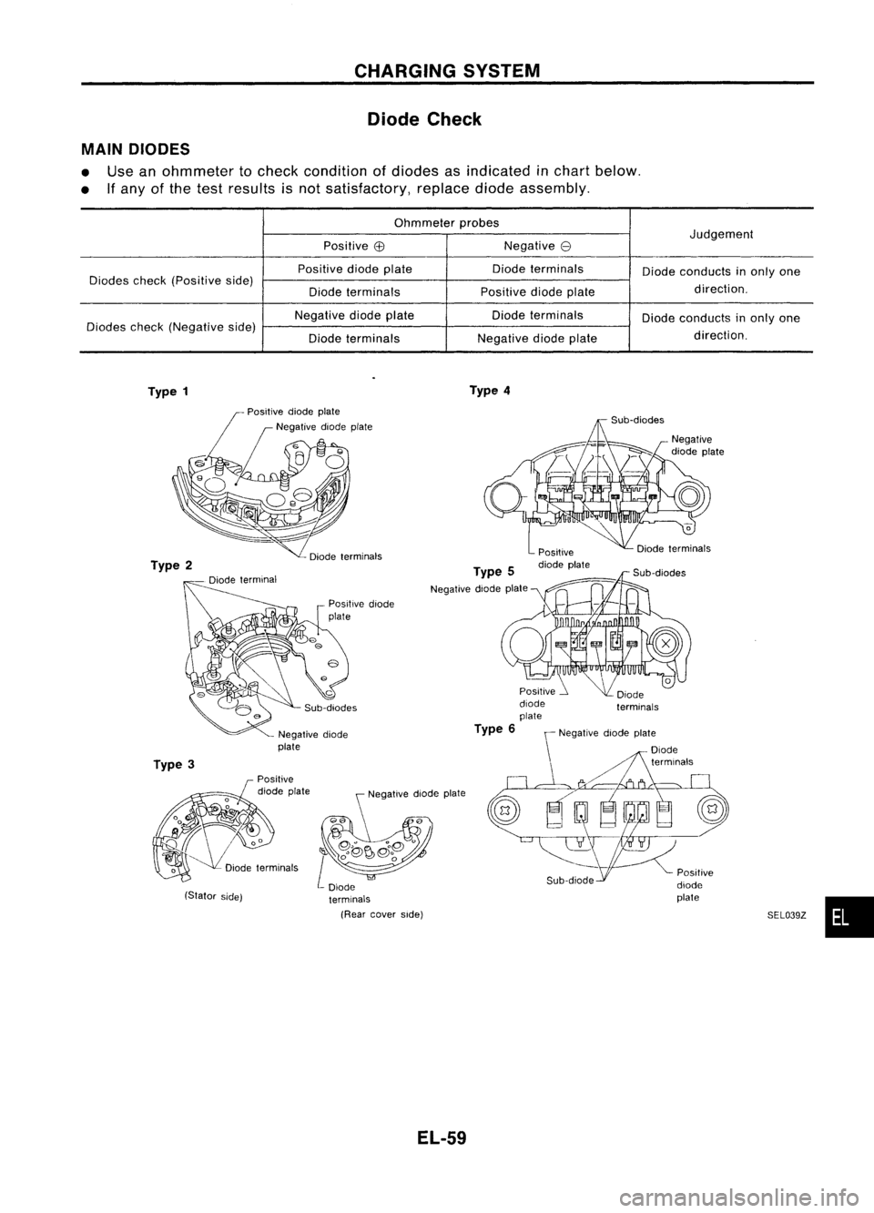
Diode Check
MAIN DIODES
• Use anohmmeter tocheck condition ofdiodes asindicated inchart below.
• Ifany ofthe test results isnot satisfactory, replacediodeassembly.
Ohmmeter probes
Judgement
Positive
EB
Negative
e
Positive diodeplate Diodeterminals
Diodeconducts inonly one
Diodes check(Positive side)
direction.
Diode terminals Positivediodeplate
Negative diodeplate Diodeterminals
Diodeconducts inonly one
Diodes check(Negative side)
direction.
Diode terminals Negative
diodeplate
Type 1 Type
4
SEL039Z•
Sub-diodes
Positive
diode plate
Type
6 \Negative diodeplate
\ Diode
terminals
Type
5
Negative diodeplate
Negative diode
plate
(Stator side)
Type
3
Type
2
EL-59
Page 432 of 1701
Amountofprotrusion:
Fix ring atthe position
OfR~~wnlmum protrusion.
,,,,'
.
~~
,
~...
\
-
,'.:'
;
.',
,
"
Eccentric '
<-'
>/
groovy
Rearbearing
SEL044Z
SEL048Z
SEl049Z CHARGING
SYSTEM
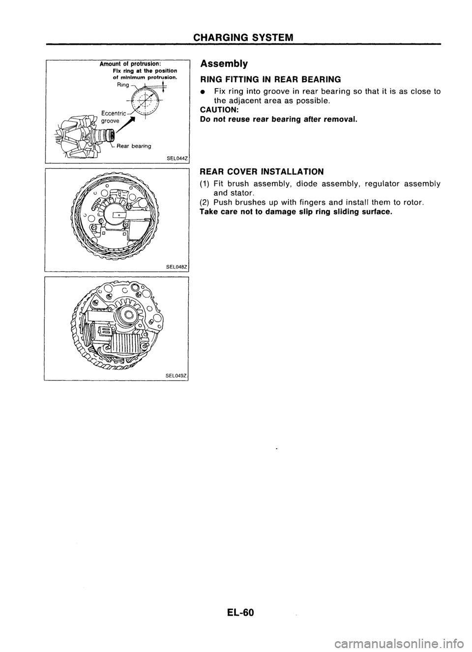
Assembly RING FITTING INREAR BEARING
• Fix ring intogroove inrear bearing sothat itis as close to
the adjacent areaaspossible.
CAUTION:
Do not reuse rearbearing afterremoval.
REAR COVER INSTALLATION
(1) Fitbrush assembly, diodeassembly, regulatorassembly
and stator.
(2) Push brushes upwith fingers andinstall themtorotor.
Take carenottodamage slipring sliding surface.
EL-60
Page 433 of 1701
CHARGINGSYSTEM
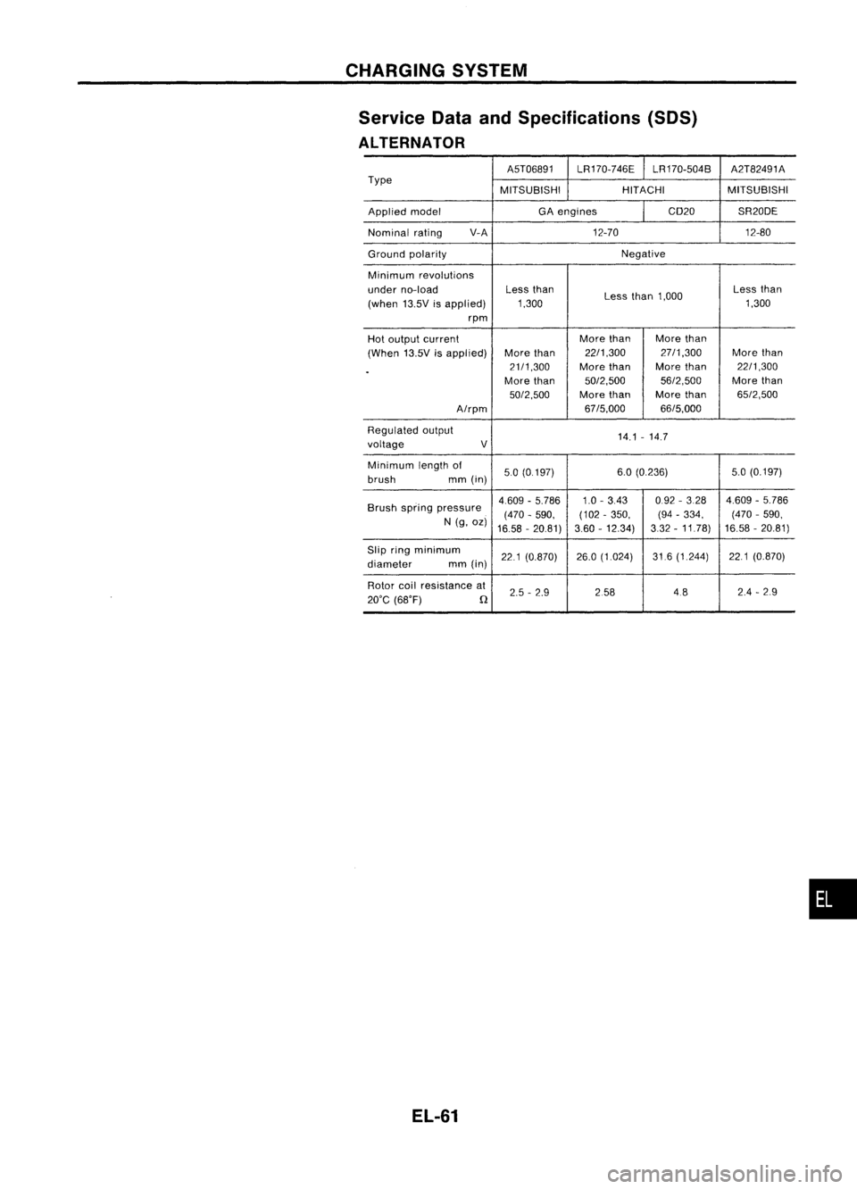
Service DataandSpecifications (SOS)
ALTERNATOR
A5T06891LR170-746E LR170-504B A2T82491A
Type MITSUBISHIHITACHIMITSUBISHI
Applied model GA
engines CD20SR20DE
Nominal rating V-A
12-70 12-80
Ground polarity Negative
Minimum revolutions
under no-load Less
than
Lessthan1,000 Less
than
(when 13.5Visapplied) 1,300 1,300
rpm
Hot output current More
than Morethan
(When 13.5Visapplied) More
than 22/1,300 27/1,300
Morethan
.
21/1,300
Morethan More
than 22/1,300
More than 50/2,500 56/2,500More
than
50/2,500 Morethan Morethan 65/2,500
A/rpm 67/5,000
66/5,000
Regulated output
14.1-14.7
voltage V
Minimum lengthof
50(0.197) 6.0
(0.236) 5.0(0.197)
brush mm(in)
Brush spring pressure 4.609
-5.786 1.0-343 0.92
-328 4.609-5.786
(470 -590, (102
-350, (94-334, (470
-590,
N (g, oz)
16.58 -20.81) 3.60
-12.34) 332-11.78) 16.58
-20.81)
Slip ringminimum
221(0.870) 26.0
(1.024) 31.6(1.244) 221(0.870)
diameter mm(in)
Rotor coilresistance at
2.5-2.9 258 4824
-29
20'C (68'F)
n
EL-61
•
Page 434 of 1701
COMBINATIONSWITCH
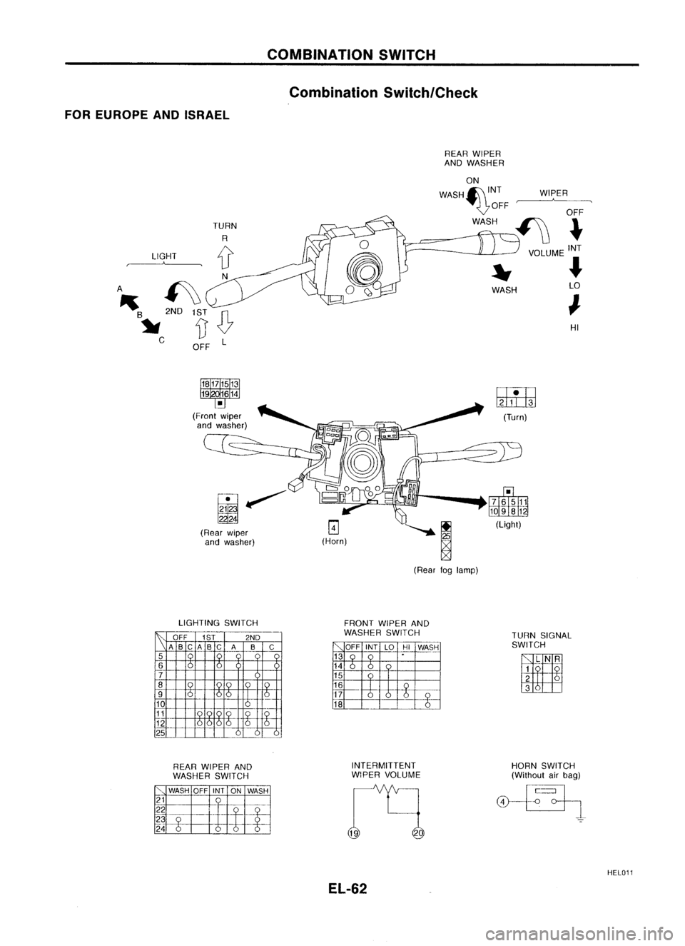
Combination Switch/Check
FOR EUROPE ANDISRAEL
LIGHT
,-A--..
1~~OFF L HI
WIPER
WASH
REAR
WIPER
AND WASHER
ON
WASH~INT ....
WASH
A ~
III
2ND
B
~ C
(Rearwiper
and washer)
@JEij
(Turn)
(Rear foglamp)
LIGHTING SWITCH
I~,
-
OFF 1ST 2ND
A BC A BC A B
C
5
r.
6
7
8
0100
9
6
616
-~
10
11
0
12
6
25
FRONT
WIPERAND
WASHER SWITCH
TURNSIGNAL
SWITCH
WI
REAR WIPER AND
WASHER SWITCH INTERMITTENT
WiPER VOLUME HORN
SWITCH
(Without airbag)
HEL011
EL-62
Page 435 of 1701
L
lJ
LIGHT
~
N
£0,
'''B
0
1ST
~
[) C
OFF
R
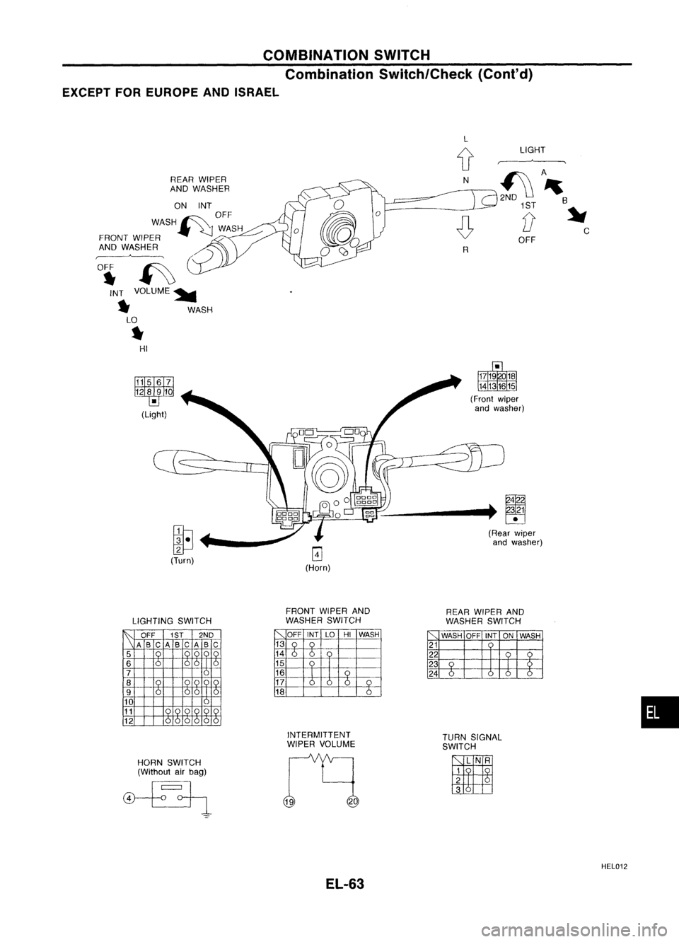
COMBINATION
SWITCH
Combination Switch/Check (Cont'd)
EXCEPT FOREUROPE ANDISRAEL
REAR WIPER
AND WASHER
ON INT
OFF
WASH~ WASH
FRONT WIPER
AND WASHER
~
°i ~
INT VOLUME~
~ WASH
LO
~ HI
~
(Turn) ~
(Horn)
:::::.------+
fl9
(Rear wiper
and washer)
LIGHTING SWITCH
~ OFF
1ST2ND
\A BC
A BCAB
C
5
0
6
6
166 6
7
8
n
9
n
:>
6
10
11
12
HORN SWITCH
(Without airbag)
FRONT
WIPERAND
WASHER SWITCH
,""
OFF
INTLOHIWASH
13
0
14
6
15
16
0
17
6
0
18
6
INTERMITTENT
WIPER VOLUME
EL-63 REAR
WIPER AND
WASHER SWITCH
WASH OFFINTONWASH
21
22
23
24
TURN SIGNAL
SWITCH
II
HEL012
•
Page 436 of 1701
\Wiper andwasher switch
~~ .~
~I!!.t:~ Switchbase COMBINATION
SWITCH
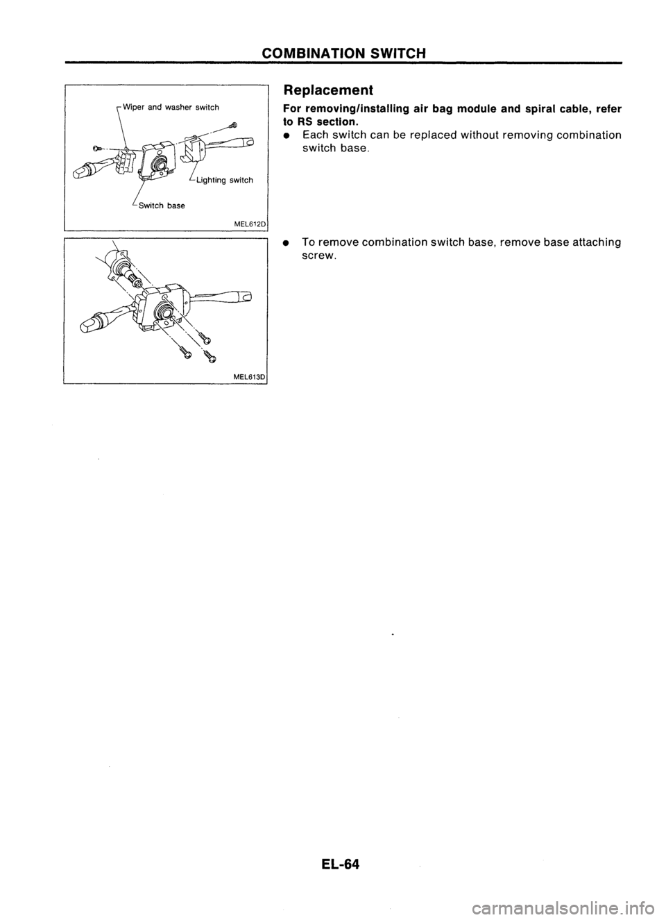
Replacement
For removing/installing airbag module andspiral cable, refer
to RS section.
• Each switch canbereplaced withoutremoving combination
switch base.
MEL612D
•Toremove combination switchbase.remove baseattaching
screw.
MEL613D
EL-64
Page 437 of 1701
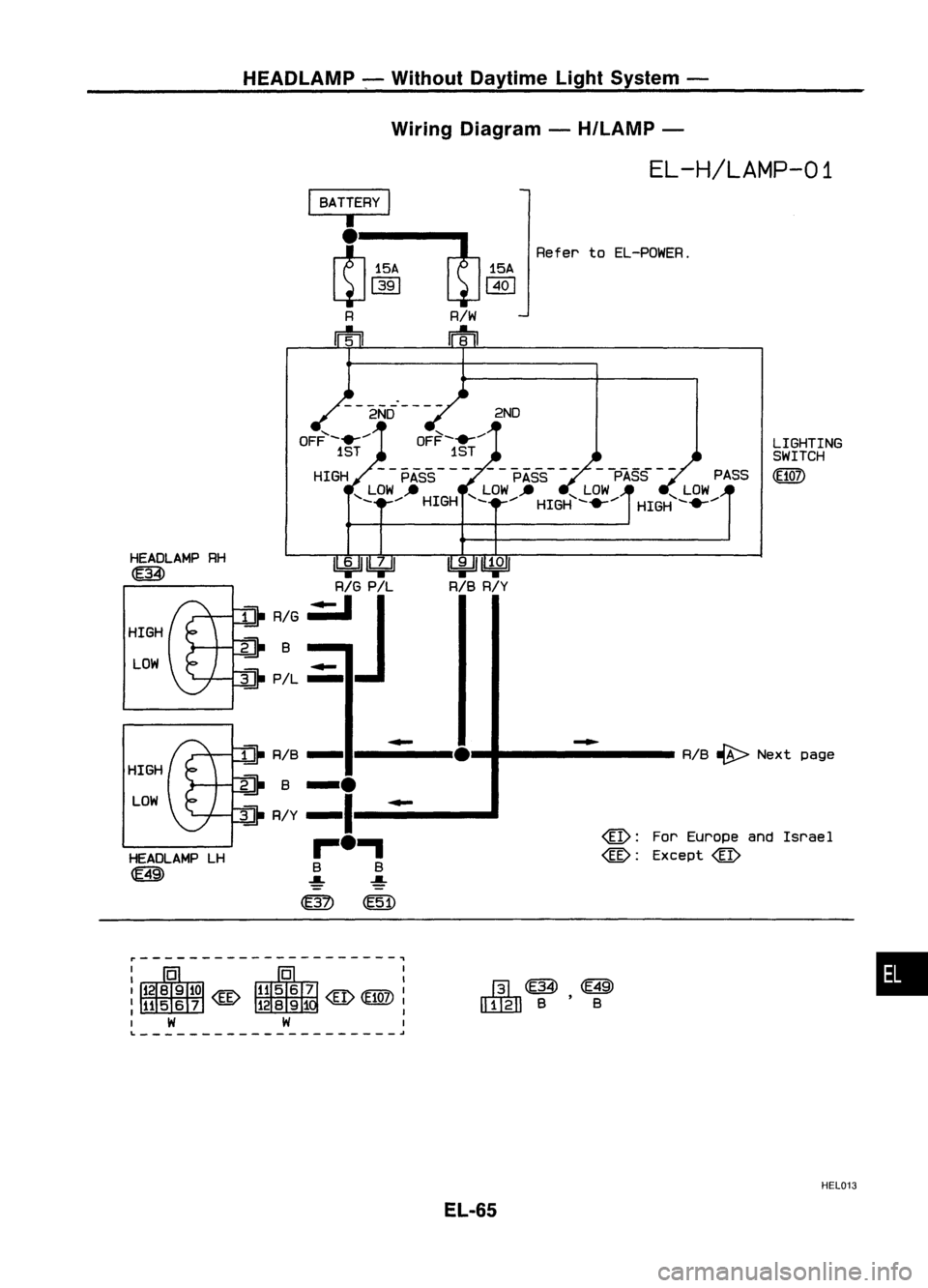
HEADLAMP-,Without Daytime LightSystem -
Wiring Diagram -H/LAMP -
I
BATTERY
I
•
~ 15'
4-1
1391
R
m
R/W
rrtil
15A
~
EL-H/LAMP-01
Refer toEL-POWER.
2ND
--2NO----
OFF'-.- ....
1ST
HIGH PASS PASS--PASS -- PASS
,LOW .. ,LOW" ,LOW ,LOW
- ....HIGH -....HIGH -.-.... HIGH-.-.... LIGHTING
SWITCH
(EtO])
r---------------------,
•
R/B
~ Next page
@:
ForEurope andIsrae 1
@:
Except
@
-
J3L
[ITgJ] B'B
lbi=IJ~
R/B R/Y
~~
R/G P!L
a-
R/G.:JJ
~B
.-
~P/L -
LOW
HEADLAMP
RH
~
i]-
R/B-
-
•
HIGH
~B-.
LOW
~R/y-I
-
HEADLAMP LH
,..-.,
~ B
B
~ ~
(ffil
@!)
HIGH
~---------------------~
HEL013
EL-65
Page 438 of 1701
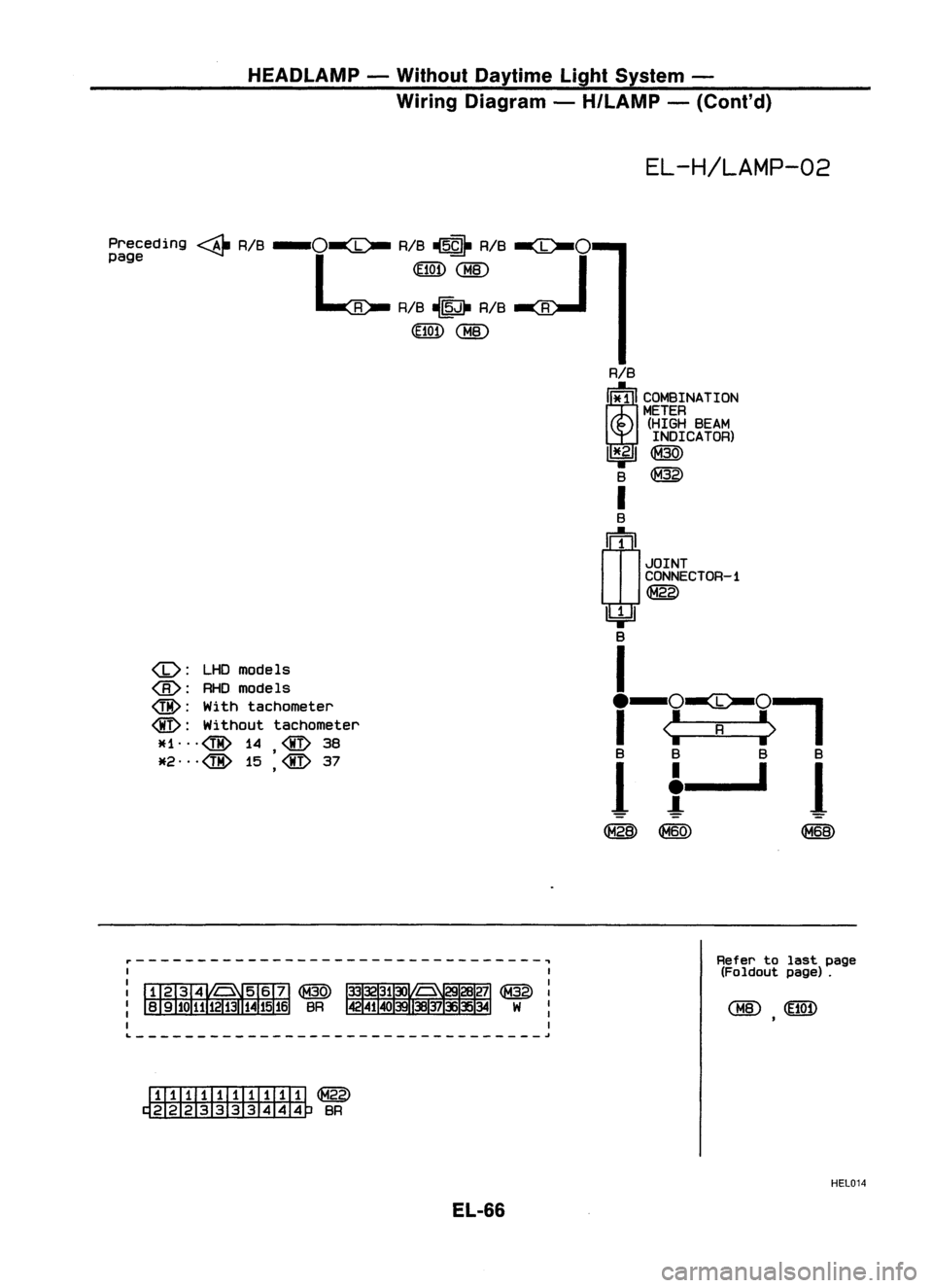
HEADLAMP-Without Daytime LightSystem -
Wiring Diagram -H/LAMP -(Cont'd)
EL-H/LAMP-02
Preceding ~RIB
-o~
RIB~ RIB
~o
page L.~
<:BID
R RIB~ RIB R
(HOf)
<:BID
:
LHDmodels
@:
RHOmodels
@:
Withtachometer
@:
Without tachometer
JU."@ 14
@
38
,
*2."@ 15
@
37
,
r---------------------------------~
I
ITITIilllIIIIIl
@
~BR
EL-66
RIB
i!i
C~INATION
METER
(HIGH BEAM
INDICATOR)
I*fl
@
8
@
I
B
~1
JOINT
CONNECTOR-1
~
~
8
I
e-o-ee-o--,
I
<:
R
:>
I
8 8 8B
1
t-~
1
@@ ~
Refer tolast page
(Foldout page).
HEL014
Page 439 of 1701
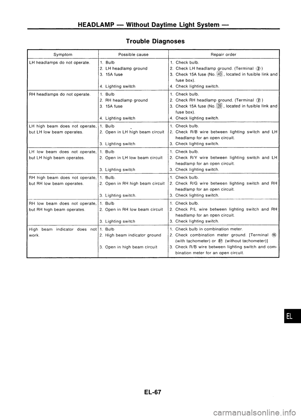
HEADLAMP-.Without Daytime LightSystem -
Trouble Diagnoses
Symptom Possiblecause Repair
order
LH
head lamps donot operate.
1.
Bulb
1.
Check bulb.
2. LH
head lamp ground
2.
Check
LH
headlamp ground.(Terminal
@)
3.
15A fuse
3.
Check
15Afuse (No.
@ill,
located infusible linkand
fuse box).
4.
Lighting switch
4.
Check
lighting switch.
RH headlamps donot operate.
1.
Bulb 1.
Check bulb.
2.
RH head lamp ground
2.
Check
RHhead lamp ground. (Terminal
@)
3
15A
fuse
3.
Check
15Afuse (No.~,located infusible linkand
fuse box).
4.
Lighting
switch
4.
Check lighting switch.
LH
high beam doesnotoperate, 1.Bulb
1. Check
bulb.
.
but
LH
low beam operates.
2.
Open in
LH
high beam circuit
r,
Check RIBwire between lightingswitch
and
LH
L.
head lamp foranopen circuit.
3.
Lighting switch
3.
Check
lighting switch.
LH
low beam doesnotoperate,
1.
Bulb
1.
Check bulb.
but
LH
high beam operates.
2.
Open
in
LH
low beam circuit
2.
Check
R/Ywire between lightingswitchand
LH
headlamp foranopen circuit.
3.
Lighting
switch
3.
Check
lighting switch.
RH high beam doesnotoperate, 1.Bulb. 1.Check
bulb.
but RHlow beam operates.
2.
Open
inRH high beam circuit
2.
Check
RIG
wire between lightingswitch
andRH
headlamp foranopen circuit.
3.
Lighting
switch.
3.
Check
lighting switch.
_.
RH low
beam doesnotoperate,
1.
Bulb 1.
Check bulb.
but RHhigh beam operates.
2.
Open
inRH low beam circuit
2.
Check
P/Lwire between lightingswitchandRH
head lamp foranopen circuit.
3.
Lighting
switch
3.
Check
lighting switch.
High beam indicator
doesnot
1.Bulb 1.Check
bulbincombination meter.
work.
2.
High
beam indicator ground
2.
Check
combination meterground. [Terminal
@
(with tachometer) or
@
(without tachometer)]
3.
Open inhigh beam circuit
3.
Check
RIBwire between lightingswitchandcom-
bination meterforanopen circuit.
EL-67
•
Page 440 of 1701
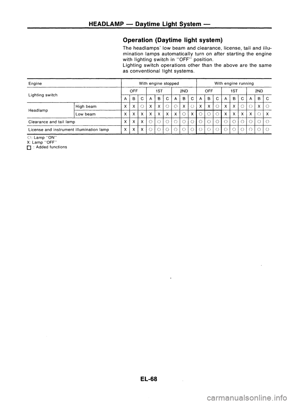
HEADLAMP-Daytime LightSystem -
Operation (Daytimelightsystem)
The headlamps' lowbeam andclearance, license,tailand illu-
mination lampsautomatically turnonafter starting theengine
with lighting switchin"OFF" position.
Lighting switchoperations otherthantheabove arethesame
as conventional lightsystems.
Engine With
engine stopped Withengine running
OFF
1ST2ND
OFF
1ST2ND
Lighting switch
B
C
A
B
C
B
C
A
B
C
B
C
A
B
C
A AA
High beam
XX
0
X
X
0
0
X
0
X
X
0
XX
0
0
X
0
Headlamp
0
0
()
0
()
Low beam
X
XX
XX
X
X
X
XXXX X
Clearance andtaillamp
X
XX
0
0
0
0
00
0
0
0
0
00
0
0
0
License andinstrument illumination lamp
X
XX
0 0
0
0
0
0
0
0 00
0
0()
0
0
0: Lamp "ON"
X: Lamp "OFF"
o :
Added functions
EL-68