NISSAN ALMERA N16 2003 Electronic Repair Manual
ALMERA N16 2003
NISSAN
NISSAN
https://www.carmanualsonline.info/img/5/57350/w960_57350-0.png
NISSAN ALMERA N16 2003 Electronic Repair Manual
Trending: FLUID, steering wheel adjustment, navigation system, Wiring diagrams, Automatic air, change language, Start
Page 2861 of 3189
COMBINATION METER CIRCUIT CHECK=NJEL0540S09
1 CHECK CONNECTOR
1. Turn ignition switch OFF.
2. Disconnect the negative battery cable.
3. Check following terminals and connector of combination meter for damage, bend and loose connection (meter-side and
harness-side).
OK or NG
OK GO TO 2.
NG Repair terminal or connector.
2 CHECK HARNESS FOR OPEN CIRCUIT
1. Disconnect combination meter connector.
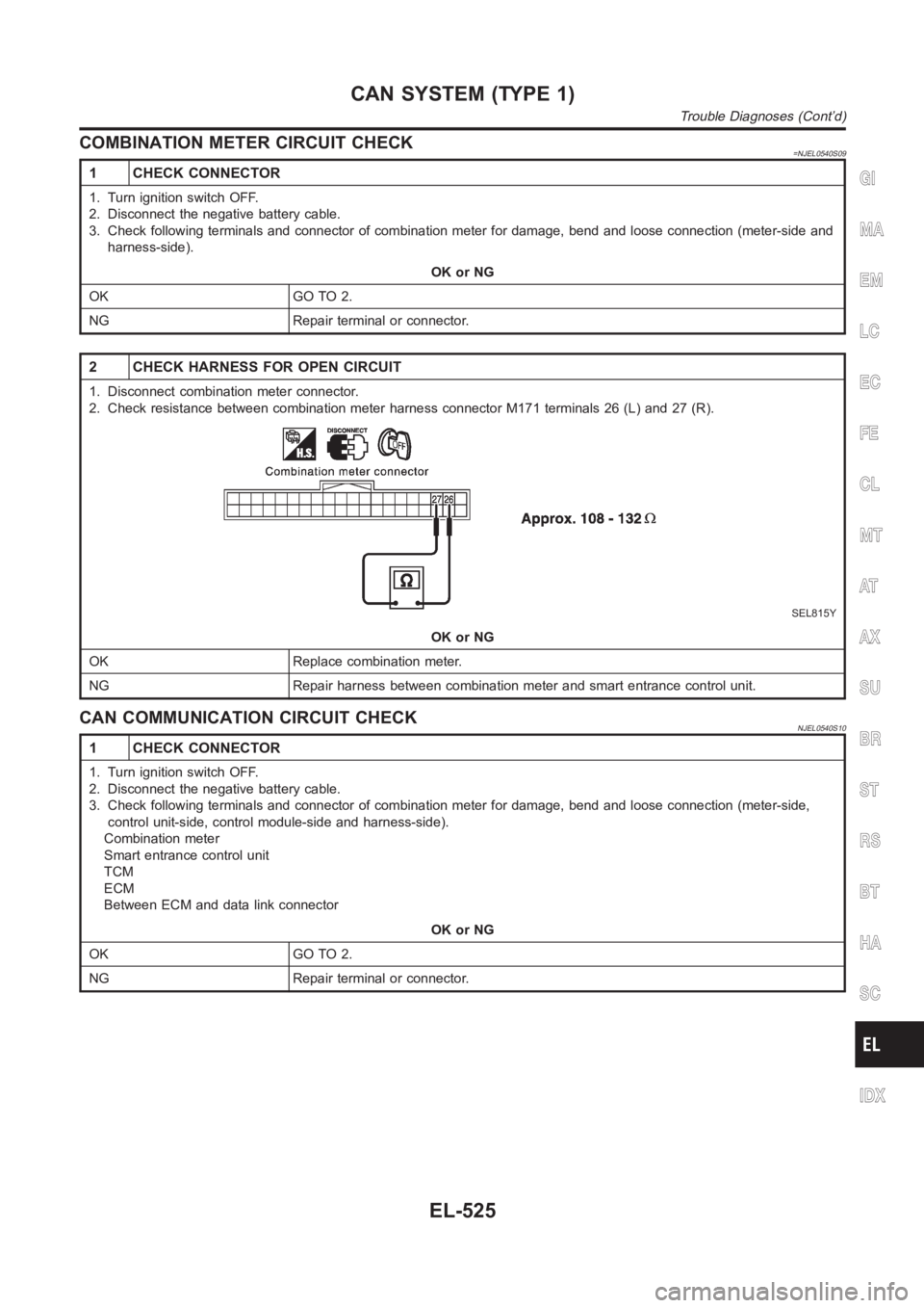
2. Check resistance between combination meter harness connector M171 terminals 26 (L) and 27 (R).
SEL815Y
OK or NG
OK Replace combination meter.
NG Repair harness between combination meter and smart entrance control unit.
CAN COMMUNICATION CIRCUIT CHECKNJEL0540S10
1 CHECK CONNECTOR
1. Turn ignition switch OFF.
2. Disconnect the negative battery cable.
3. Check following terminals and connector of combination meter for damage, bend and loose connection (meter-side,
control unit-side, control module-side and harness-side).
Combination meter
Smart entrance control unit
TCM
ECM
Between ECM and data link connector
OK or NG
OK GO TO 2.
NG Repair terminal or connector.
GI
MA
EM
LC
EC
FE
CL
MT
AT
AX
SU
BR
ST
RS
BT
HA
SC
IDX
CAN SYSTEM (TYPE 1)
Trouble Diagnoses (Cont’d)
EL-525
Page 2862 of 3189
2 CHECK HARNESS FOR SHORT CIRCUIT
1. Disconnect combination meter connector, smart entrance control unit connector and harness connector M202 (LHD
models) or harness connector M159 (RHD models).
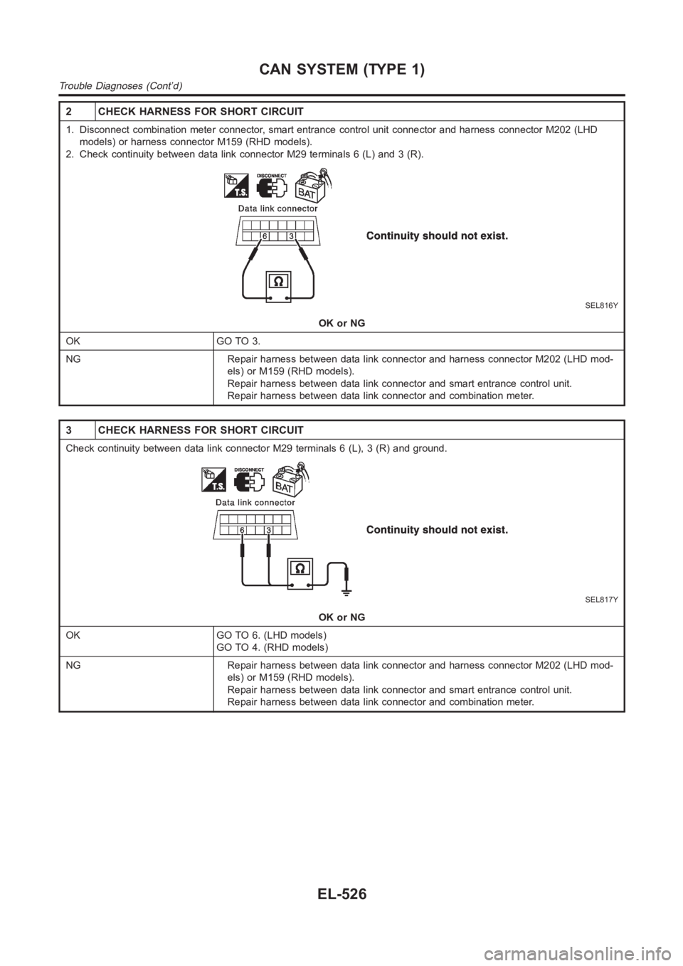
2. Check continuity between data link connector M29 terminals 6 (L) and 3 (R).
SEL816Y
OK or NG
OK GO TO 3.
NG Repair harness between data link connector and harness connector M202 (LHD mod-
els) or M159 (RHD models).
Repair harness between data link connector and smart entrance control unit.
Repair harness between data link connector and combination meter.
3 CHECK HARNESS FOR SHORT CIRCUIT
Check continuity between data link connector M29 terminals 6 (L), 3 (R) andground.
SEL817Y
OK or NG
OK GO TO 6. (LHD models)
GO TO 4. (RHD models)
NG Repair harness between data link connector and harness connector M202 (LHD mod-
els) or M159 (RHD models).
Repair harness between data link connector and smart entrance control unit.
Repair harness between data link connector and combination meter.
CAN SYSTEM (TYPE 1)
Trouble Diagnoses (Cont’d)
EL-526
Page 2863 of 3189
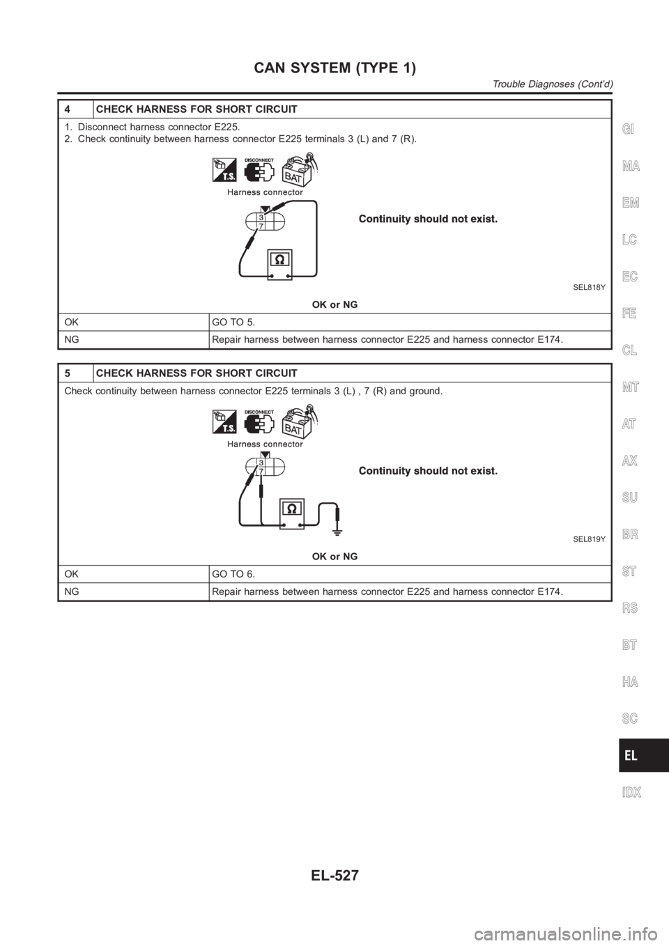
4 CHECK HARNESS FOR SHORT CIRCUIT
1. Disconnect harness connector E225.
2. Check continuity between harness connector E225 terminals 3 (L) and 7 (R).
SEL818Y
OK or NG
OK GO TO 5.
NG Repair harness between harness connector E225 and harness connector E174.
5 CHECK HARNESS FOR SHORT CIRCUIT
Check continuity between harness connector E225 terminals 3 (L) , 7 (R) andground.
SEL819Y
OK or NG
OK GO TO 6.
NG Repair harness between harness connector E225 and harness connector E174.
GI
MA
EM
LC
EC
FE
CL
MT
AT
AX
SU
BR
ST
RS
BT
HA
SC
IDX
CAN SYSTEM (TYPE 1)
Trouble Diagnoses (Cont’d)
EL-527
Page 2864 of 3189
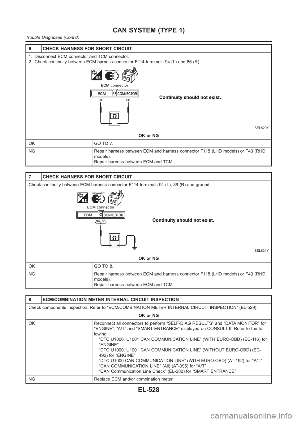
6 CHECK HARNESS FOR SHORT CIRCUIT
1. Disconnect ECM connector and TCM connector.
2. Check continuity between ECM harness connector F114 terminals 94 (L) and86(R).
SEL820Y
OK or NG
OK GO TO 7.
NG Repair harness between ECM and harness connector F115 (LHD models) or F43 (RHD
models).
Repair harness between ECM and TCM.
7 CHECK HARNESS FOR SHORT CIRCUIT
Check continuity between ECM harness connector F114 terminals 94 (L), 86 (R) and ground.
SEL821Y
OK or NG
OK GO TO 8.
NG Repair harness between ECM and harness connector F115 (LHD models) or F43 (RHD
models).
Repair harness between ECM and TCM.
8 ECM/COMBINATION METER INTERNAL CIRCUIT INSPECTION
Check components inspection. Refer to “ECM/COMBINATION METER INTERNAL CIRCUIT INSPECTION” (EL-529).
OK or NG
OK Reconnect all connectors to perform “SELF-DIAG RESULTS” and “DATA MONITOR” for
“ENGINE”, “A/T” and “SMART ENTRANCE” displayed on CONSULT-II. Refer to thefol-
lowing.
“DTC U1000, U1001 CAN COMMUNICATION LINE” (WITH EURO-OBD) (EC-116) for
“ENGINE”
“DTC U1000, U1001 CAN COMMUNICATION LINE” (WITHOUT EURO-OBD) (EC-
492) for “ENGINE”
“DTC U1000 CAN COMMUNICATION LINE” (WITH EURO-OBD) (AT-192) for “A/T”
“CAN COMMUNICATION LINE” (All) (AT-395) for “A/T”
“CAN Communication Line Check” (EL-380) for “SMART ENTRANCE”
NG Replace ECM and/or combination meter.
CAN SYSTEM (TYPE 1)
Trouble Diagnoses (Cont’d)
EL-528
Page 2865 of 3189
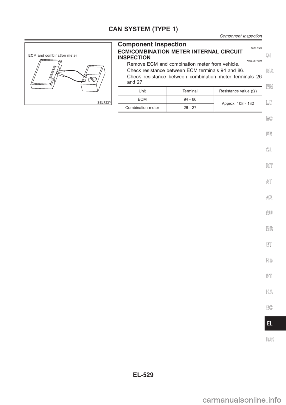
SEL723Y
Component InspectionNJEL0541ECM/COMBINATION METER INTERNAL CIRCUIT
INSPECTION
NJEL0541S01Remove ECM and combination meter from vehicle.
Check resistance between ECM terminals 94 and 86.
Check resistance between combination meter terminals 26
and 27.
Unit Terminal Resistance value (Ω)
ECM 94 - 86
Approx. 108 - 132
Combination meter 26 - 27
GI
MA
EM
LC
EC
FE
CL
MT
AT
AX
SU
BR
ST
RS
BT
HA
SC
IDX
CAN SYSTEM (TYPE 1)
Component Inspection
EL-529
Page 2866 of 3189
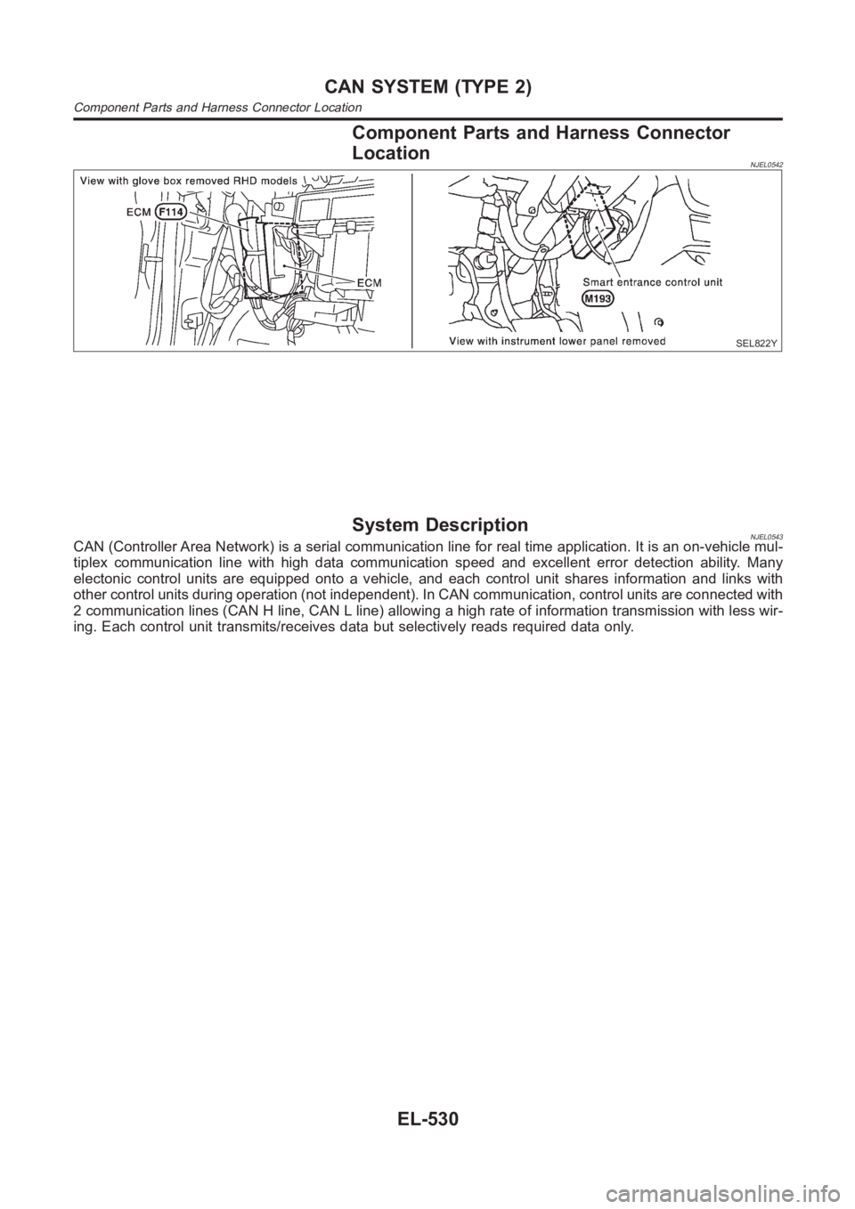
Component Parts and Harness Connector
Location
NJEL0542
SEL822Y
System DescriptionNJEL0543CAN (Controller Area Network) is a serial communication line for real timeapplication. It is an on-vehicle mul-
tiplex communication line with high data communication speed and excellent error detection ability. Many
electonic control units are equipped onto a vehicle, and each control unitshares information and links with
other control units during operation (not independent). In CAN communication, control units are connected with
2 communication lines (CAN H line, CAN L line) allowing a high rate of information transmission with less wir-
ing. Each control unit transmits/receives data but selectively reads requireddataonly.
CAN SYSTEM (TYPE 2)
Component Parts and Harness Connector Location
EL-530
Page 2867 of 3189
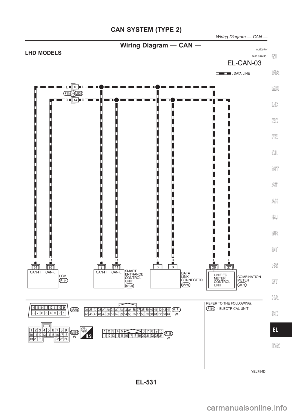
Wiring Diagram — CAN —NJEL0544LHD MODELSNJEL0544S01
YEL784D
GI
MA
EM
LC
EC
FE
CL
MT
AT
AX
SU
BR
ST
RS
BT
HA
SC
IDX
CAN SYSTEM (TYPE 2)
Wiring Diagram — CAN —
EL-531
Page 2868 of 3189
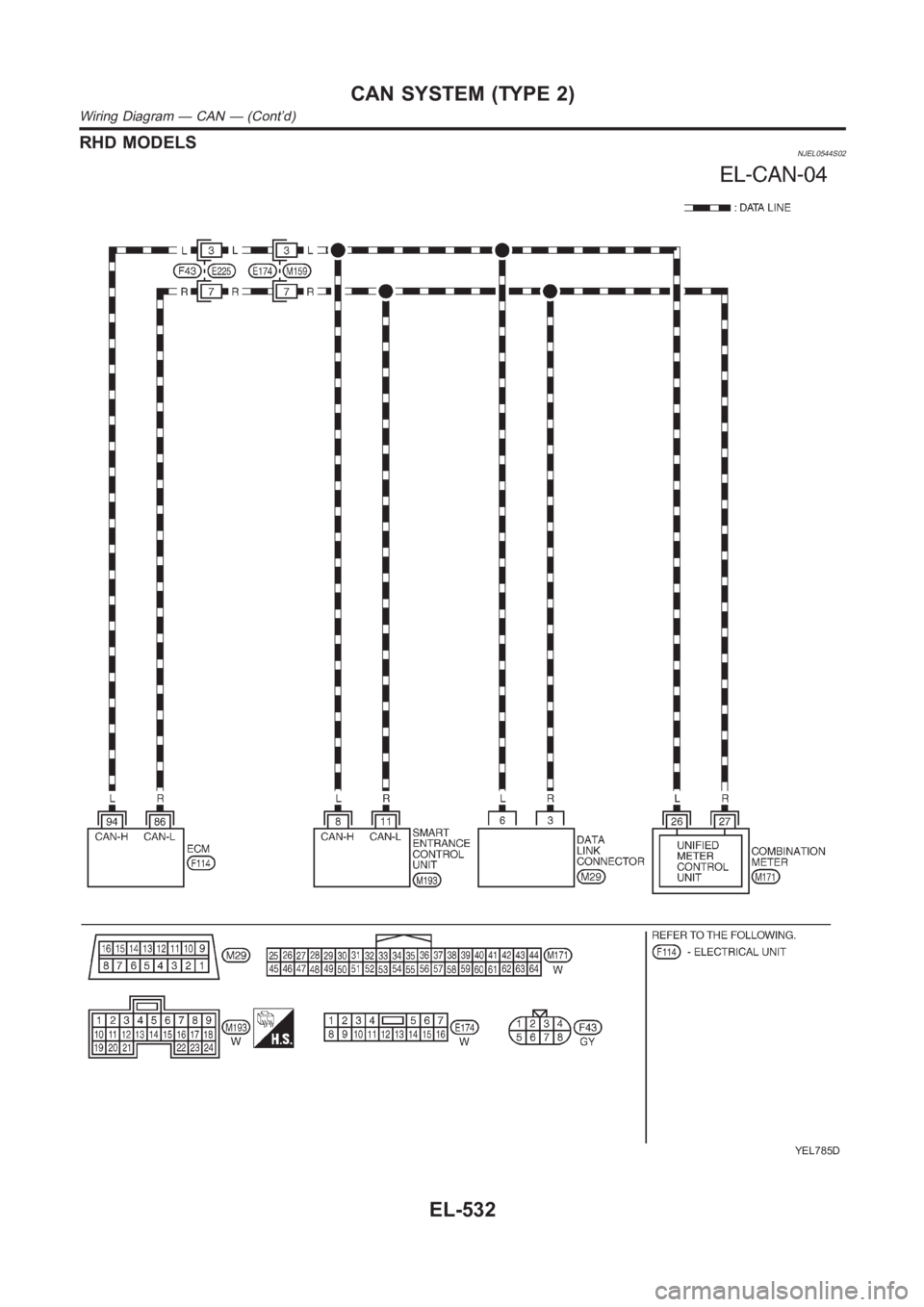
RHD MODELSNJEL0544S02
YEL785D
CAN SYSTEM (TYPE 2)
Wiring Diagram — CAN — (Cont’d)
EL-532
Page 2869 of 3189
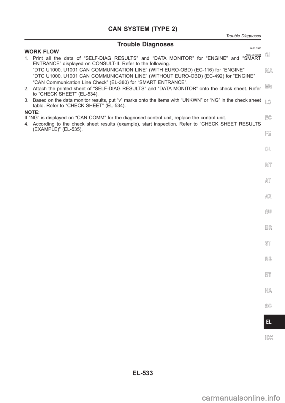
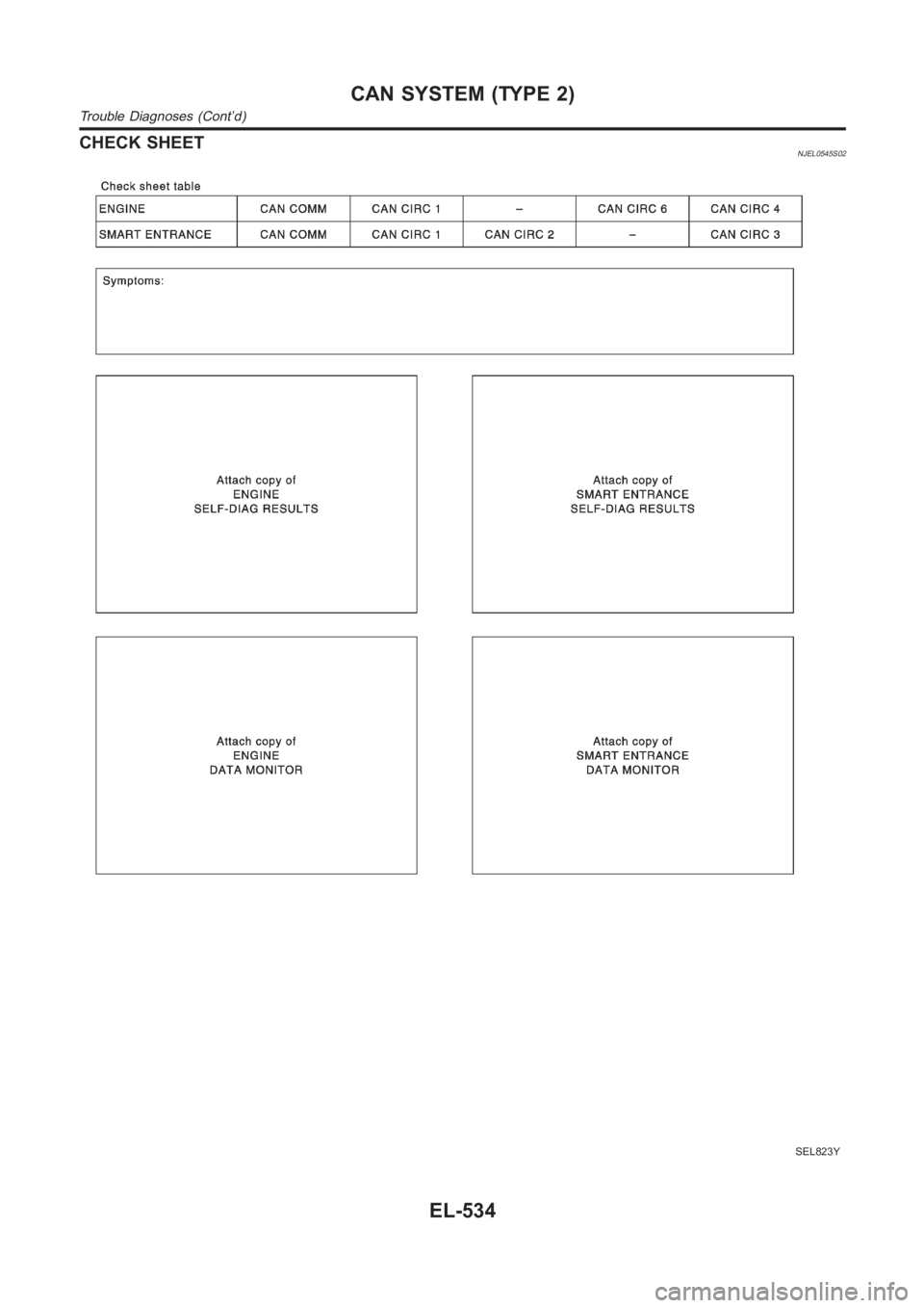
Trouble DiagnosesNJEL0545WORK FLOWNJEL0545S011. Print all the data of “SELF-DIAG RESULTS” and “DATA MONITOR” for “ENGINE” and “SMART
ENTRANCE” displayed on CONSULT-II. Refer to the following.
“DTC U1000, U1001 CAN COMMUNICATION LINE” (WITH EURO-OBD) (EC-116) for “ENGINE”
“DTC U1000, U1001 CAN COMMUNICATION LINE” (WITHOUT EURO-OBD) (EC-492) for “ENGINE”
“CAN Communication Line Check” (EL-380) for “SMART ENTRANCE”.
2. Attach the printed sheet of “SELF-DIAG RESULTS” and “DATA MONITOR” ontothe check sheet. Refer
to “CHECK SHEET” (EL-534).
3. Based on the data monitor results, put “v” marks onto the items with “UNKWN” or “NG” in the check sheet
table. Refer to “CHECK SHEET” (EL-534).
NOTE:
If “NG” is displayed on “CAN COMM” for the diagnosed control unit, replace the control unit.
4. According to the check sheet results (example), start inspection. Refer to “CHECK SHEET RESULTS
(EXAMPLE)” (EL-535).GI
MA
EM
LC
EC
FE
CL
MT
AT
AX
SU
BR
ST
RS
BT
HA
SC
IDX
CAN SYSTEM (TYPE 2)
Trouble Diagnoses
EL-533
Page 2870 of 3189
CHECK SHEETNJEL0545S02
SEL823Y
CAN SYSTEM (TYPE 2)
Trouble Diagnoses (Cont’d)
EL-534
Trending: ECO mode, remote start, Air conditioner, trailer, schematic, warning lights, jack points


