NISSAN ALMERA N16 2003 Electronic Repair Manual
ALMERA N16 2003
NISSAN
NISSAN
https://www.carmanualsonline.info/img/5/57350/w960_57350-0.png
NISSAN ALMERA N16 2003 Electronic Repair Manual
Trending: ydec, EC-265, brake light, spark plugs replace, load capacity, bolt pattern, air condition
Page 2871 of 3189
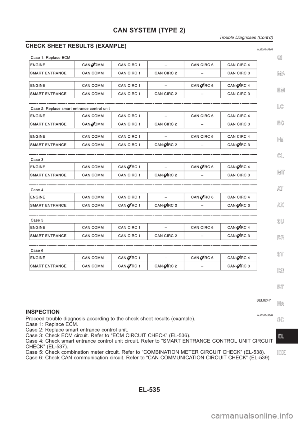
CHECK SHEET RESULTS (EXAMPLE)NJEL0545S03
SEL824Y
INSPECTIONNJEL0545S04Proceed trouble diagnosis according to the check sheet results (example).
Case 1: Replace ECM.
Case 2: Replace smart entrance control unit.
Case 3: Check ECM circuit. Refer to “ECM CIRCUIT CHECK” (EL-536).
Case 4: Check smart entrance control unit circuit. Refer to “SMART ENTRANCE CONTROL UNIT CIRCUIT
CHECK” (EL-537).
Case 5: Check combination meter circuit. Refer to “COMBINATION METER CIRCUIT CHECK” (EL-538).
Case 6: Check CAN communication circuit. Refer to “CAN COMMUNICATION CIRCUIT CHECK” (EL-539).
GI
MA
EM
LC
EC
FE
CL
MT
AT
AX
SU
BR
ST
RS
BT
HA
SC
IDX
CAN SYSTEM (TYPE 2)
Trouble Diagnoses (Cont’d)
EL-535
Page 2872 of 3189
ECM CIRCUIT CHECKNJEL0545S05
1 CHECK CONNECTOR
1. Turn ignition switch OFF.
2. Disconnect the negative battery cable.
3. Check following terminals and connector for damage, bend and loose connection (control module-side and harness-
side).
LHD models
ECM
Harness connector F115
Harness connector M202
RHD models
ECM
Harness connector F43
Harness connector E225
Harness connector E174
Harness connector M159
OK or NG
OK GO TO 2.
NG Repair terminal or connector.
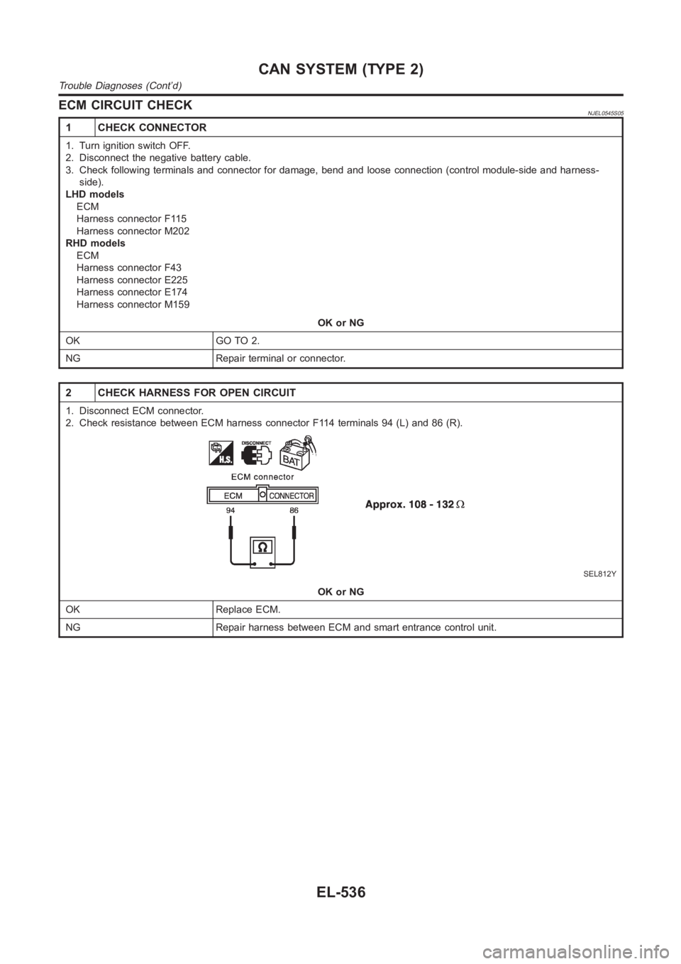
2 CHECK HARNESS FOR OPEN CIRCUIT
1. Disconnect ECM connector.
2. Check resistance between ECM harness connector F114 terminals 94 (L) and86(R).
SEL812Y
OK or NG
OK Replace ECM.
NG Repair harness between ECM and smart entrance control unit.
CAN SYSTEM (TYPE 2)
Trouble Diagnoses (Cont’d)
EL-536
Page 2873 of 3189
SMART ENTRANCE CONTROL UNIT CIRCUIT CHECK=NJEL0545S06
1 CHECK CONNECTOR
1. Turn ignition switch OFF.
2. Disconnect the negative battery cable.
3. Check terminals and connector of smart entrance control unit for damage, bend and loose connection (control unit-side
and harness-side).
OK or NG
OK GO TO 2.
NG Repair terminal or connector.
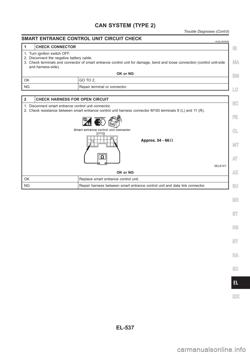
2 CHECK HARNESS FOR OPEN CIRCUIT
1. Disconnect smart entrance control unit connector.
2. Check resistance between smart entrance control unit harness connector M193 terminals 8 (L) and 11 (R).
SEL814Y
OK or NG
OK Replace smart entrance control unit.
NG Repair harness between smart entrance control unit and data link connector.
GI
MA
EM
LC
EC
FE
CL
MT
AT
AX
SU
BR
ST
RS
BT
HA
SC
IDX
CAN SYSTEM (TYPE 2)
Trouble Diagnoses (Cont’d)
EL-537
Page 2874 of 3189
COMBINATION METER CIRCUIT CHECK=NJEL0545S07
1 CHECK CONNECTOR
1. Turn ignition switch OFF.
2. Disconnect the negative battery cable.
3. Check terminals and connector of combination meter for damage, bend andloose connection (meter-side and harness-
side).
OK or NG
OK GO TO 2.
NG Repair terminal or connector.
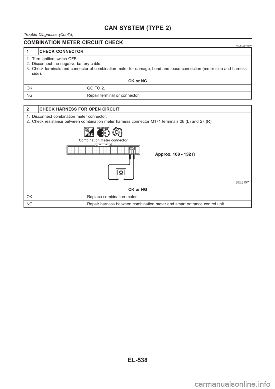
2 CHECK HARNESS FOR OPEN CIRCUIT
1. Disconnect combination meter connector.
2. Check resistance between combination meter harness connector M171 terminals 26 (L) and 27 (R).
SEL815Y
OK or NG
OK Replace combination meter.
NG Repair harness between combination meter and smart entrance control unit.
CAN SYSTEM (TYPE 2)
Trouble Diagnoses (Cont’d)
EL-538
Page 2875 of 3189
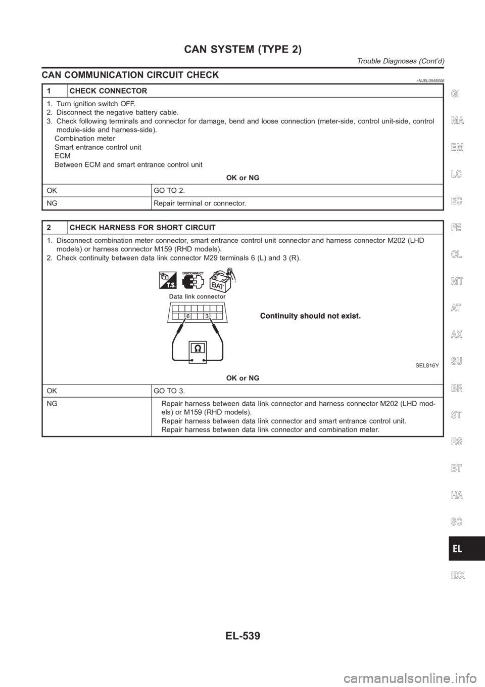
CAN COMMUNICATION CIRCUIT CHECK=NJEL0545S08
1 CHECK CONNECTOR
1. Turn ignition switch OFF.
2. Disconnect the negative battery cable.
3. Check following terminals and connector for damage, bend and loose connection (meter-side, control unit-side, control
module-side and harness-side).
Combination meter
Smart entrance control unit
ECM
Between ECM and smart entrance control unit
OK or NG
OK GO TO 2.
NG Repair terminal or connector.
2 CHECK HARNESS FOR SHORT CIRCUIT
1. Disconnect combination meter connector, smart entrance control unit connector and harness connector M202 (LHD
models) or harness connector M159 (RHD models).
2. Check continuity between data link connector M29 terminals 6 (L) and 3 (R).
SEL816Y
OK or NG
OK GO TO 3.
NG Repair harness between data link connector and harness connector M202 (LHD mod-
els) or M159 (RHD models).
Repair harness between data link connector and smart entrance control unit.
Repair harness between data link connector and combination meter.
GI
MA
EM
LC
EC
FE
CL
MT
AT
AX
SU
BR
ST
RS
BT
HA
SC
IDX
CAN SYSTEM (TYPE 2)
Trouble Diagnoses (Cont’d)
EL-539
Page 2876 of 3189
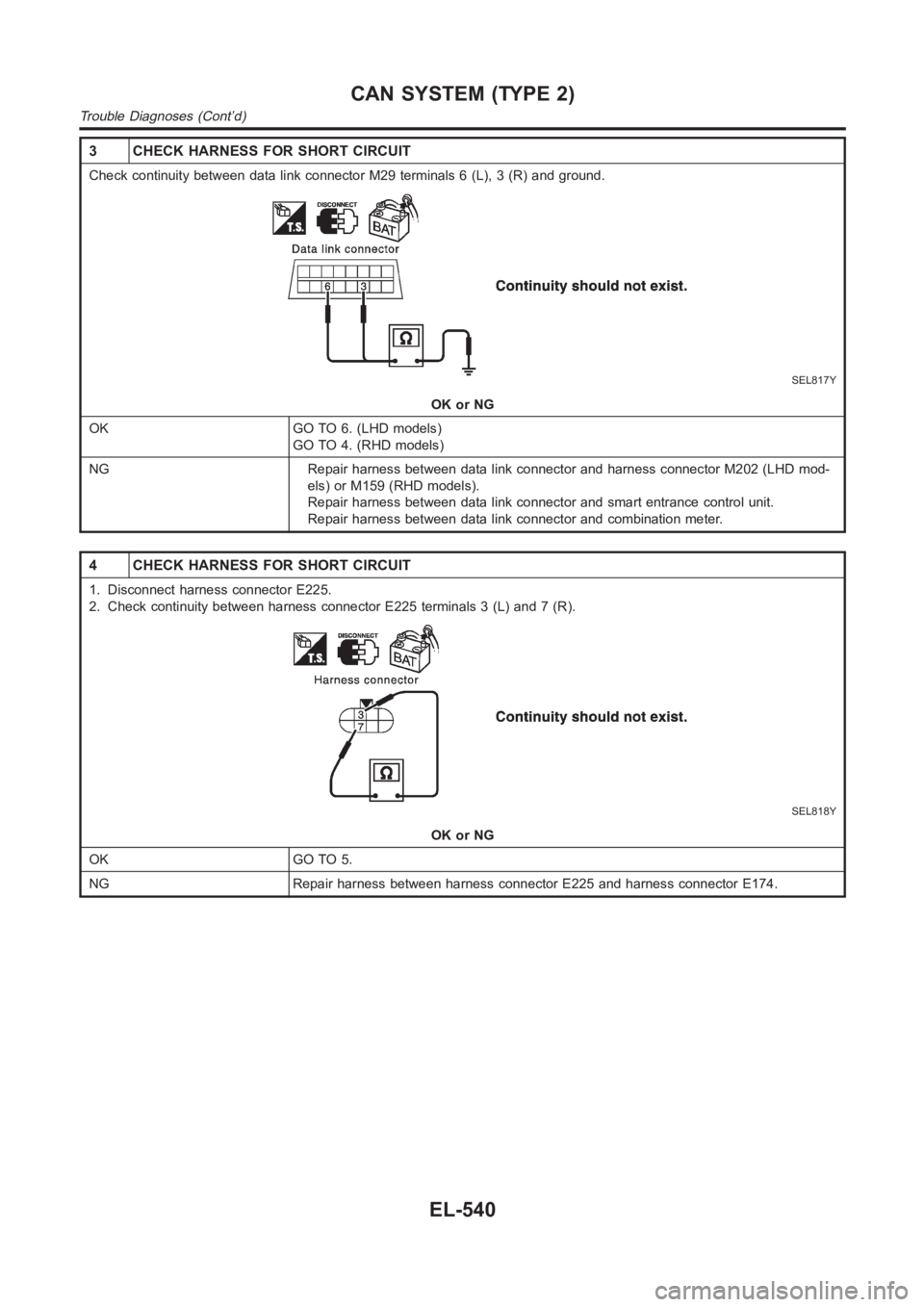
3 CHECK HARNESS FOR SHORT CIRCUIT
Check continuity between data link connector M29 terminals 6 (L), 3 (R) andground.
SEL817Y
OK or NG
OK GO TO 6. (LHD models)
GO TO 4. (RHD models)
NG Repair harness between data link connector and harness connector M202 (LHD mod-
els) or M159 (RHD models).
Repair harness between data link connector and smart entrance control unit.
Repair harness between data link connector and combination meter.
4 CHECK HARNESS FOR SHORT CIRCUIT
1. Disconnect harness connector E225.
2. Check continuity between harness connector E225 terminals 3 (L) and 7 (R).
SEL818Y
OK or NG
OK GO TO 5.
NG Repair harness between harness connector E225 and harness connector E174.
CAN SYSTEM (TYPE 2)
Trouble Diagnoses (Cont’d)
EL-540
Page 2877 of 3189
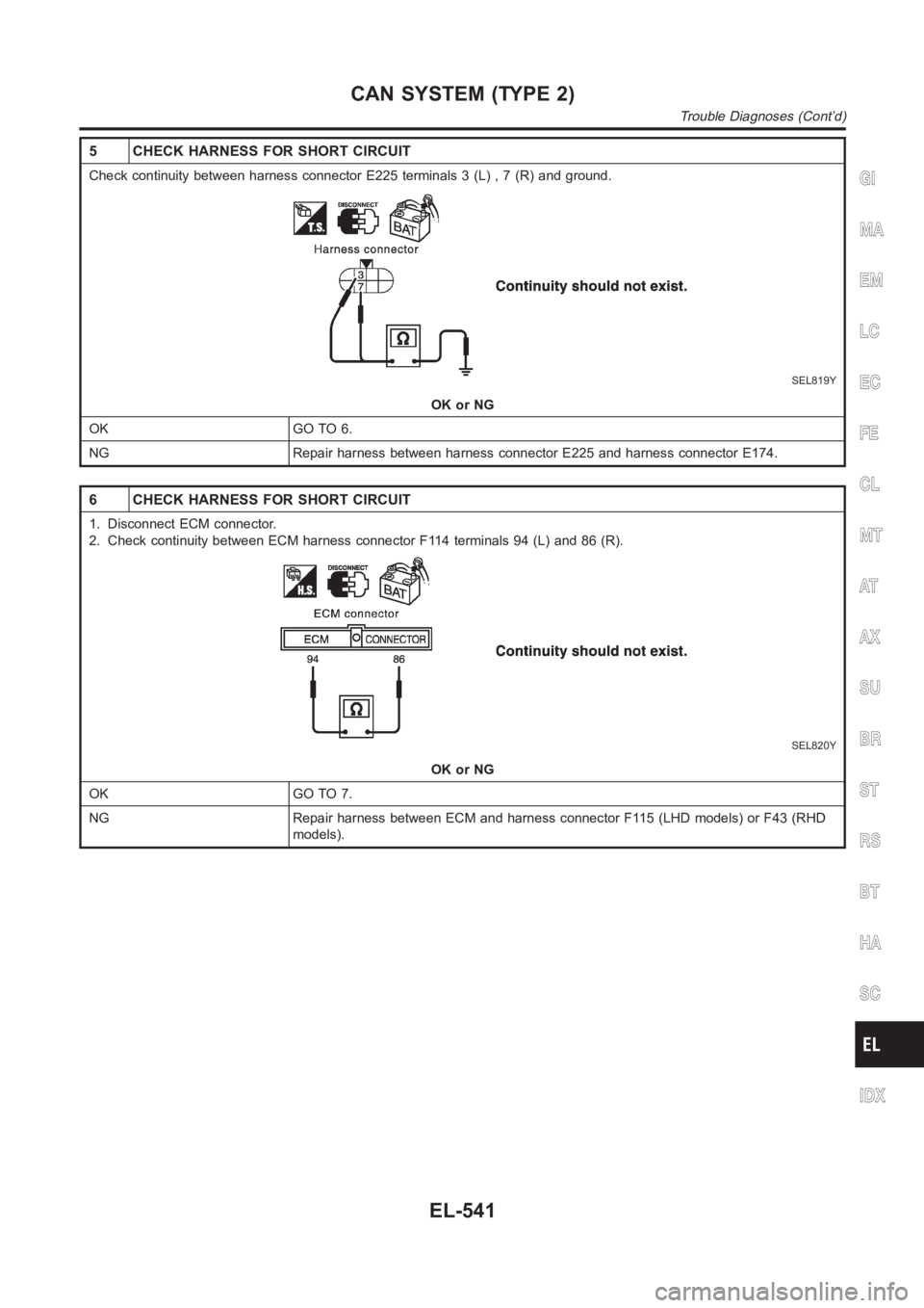
5 CHECK HARNESS FOR SHORT CIRCUIT
Check continuity between harness connector E225 terminals 3 (L) , 7 (R) andground.
SEL819Y
OK or NG
OK GO TO 6.
NG Repair harness between harness connector E225 and harness connector E174.
6 CHECK HARNESS FOR SHORT CIRCUIT
1. Disconnect ECM connector.
2. Check continuity between ECM harness connector F114 terminals 94 (L) and86(R).
SEL820Y
OK or NG
OK GO TO 7.
NG Repair harness between ECM and harness connector F115 (LHD models) or F43 (RHD
models).
GI
MA
EM
LC
EC
FE
CL
MT
AT
AX
SU
BR
ST
RS
BT
HA
SC
IDX
CAN SYSTEM (TYPE 2)
Trouble Diagnoses (Cont’d)
EL-541
Page 2878 of 3189
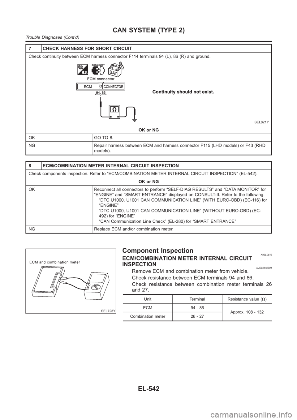
7 CHECK HARNESS FOR SHORT CIRCUIT
Check continuity between ECM harness connector F114 terminals 94 (L), 86 (R) and ground.
SEL821Y
OK or NG
OK GO TO 8.
NG Repair harness between ECM and harness connector F115 (LHD models) or F43 (RHD
models).
8 ECM/COMBINATION METER INTERNAL CIRCUIT INSPECTION
Check components inspection. Refer to “ECM/COMBINATION METER INTERNAL CIRCUIT INSPECTION” (EL-542).
OK or NG
OK Reconnect all connectors to perform “SELF-DIAG RESULTS” and “DATA MONITOR” for
“ENGINE” and “SMART ENTRANCE” displayed on CONSULT-II. Refer to the following.
“DTC U1000, U1001 CAN COMMUNICATION LINE” (WITH EURO-OBD) (EC-116) for
“ENGINE”
“DTC U1000, U1001 CAN COMMUNICATION LINE” (WITHOUT EURO-OBD) (EC-
492) for “ENGINE”
“CAN Communication Line Check” (EL-380) for “SMART ENTRANCE”
NG Replace ECM and/or combination meter.
SEL723Y
Component InspectionNJEL0546ECM/COMBINATION METER INTERNAL CIRCUIT
INSPECTION
NJEL0546S01Remove ECM and combination meter from vehicle.
Check resistance between ECM terminals 94 and 86.
Check resistance between combination meter terminals 26
and 27.
Unit Terminal Resistance value (Ω)
ECM 94 - 86
Approx. 108 - 132
Combination meter 26 - 27
CAN SYSTEM (TYPE 2)
Trouble Diagnoses (Cont’d)
EL-542
Page 2879 of 3189
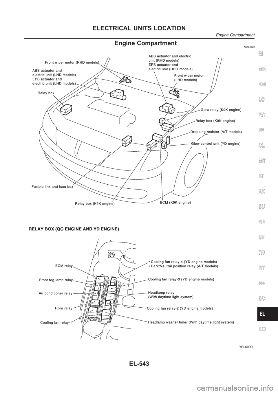
Engine CompartmentNJEL0129
YEL609D
GI
MA
EM
LC
EC
FE
CL
MT
AT
AX
SU
BR
ST
RS
BT
HA
SC
IDX
ELECTRICAL UNITS LOCATION
Engine Compartment
EL-543
Page 2880 of 3189
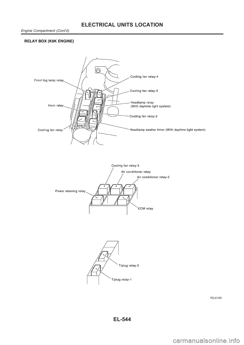
YEL610D
ELECTRICAL UNITS LOCATION
Engine Compartment (Cont’d)
EL-544
Trending: brake light, cooling, immobilize, trunk, service schedule, Speaker, Window defogger
