NISSAN ALMERA N16 2003 Electronic Repair Manual
ALMERA N16 2003
NISSAN
NISSAN
https://www.carmanualsonline.info/img/5/57350/w960_57350-0.png
NISSAN ALMERA N16 2003 Electronic Repair Manual
Trending: blower, iat, junction box b4, power windows, neutral, buttons, Window defogger
Page 2851 of 3189
Trouble DiagnosesNJEL0540WORK FLOWNJEL0540S011. Print all the data of “SELF-DIAG RESULTS” and “DATA MONITOR” for “ENGINE”, “A/T” and “SMART
ENTRANCE” displayed on CONSULT-II. Refer to the following.
“DTC U1000, U1001 CAN COMMUNICATION LINE” (WITH EURO-OBD) (EC-116) for “ENGINE”
“DTC U1000, U1001 CAN COMMUNICATION LINE” (WITHOUT EURO-OBD) (EC-492) for “ENGINE”
“DTC U1000 CAN COMMUNICATION LINE” (WITH EURO-OBD) (AT-192) for “A/T”
“CAN COMMUNICATION LINE” (All) (AT-395) for “A/T”
“CAN Communication Line Check” (EL-380) for “SMART ENTRANCE”
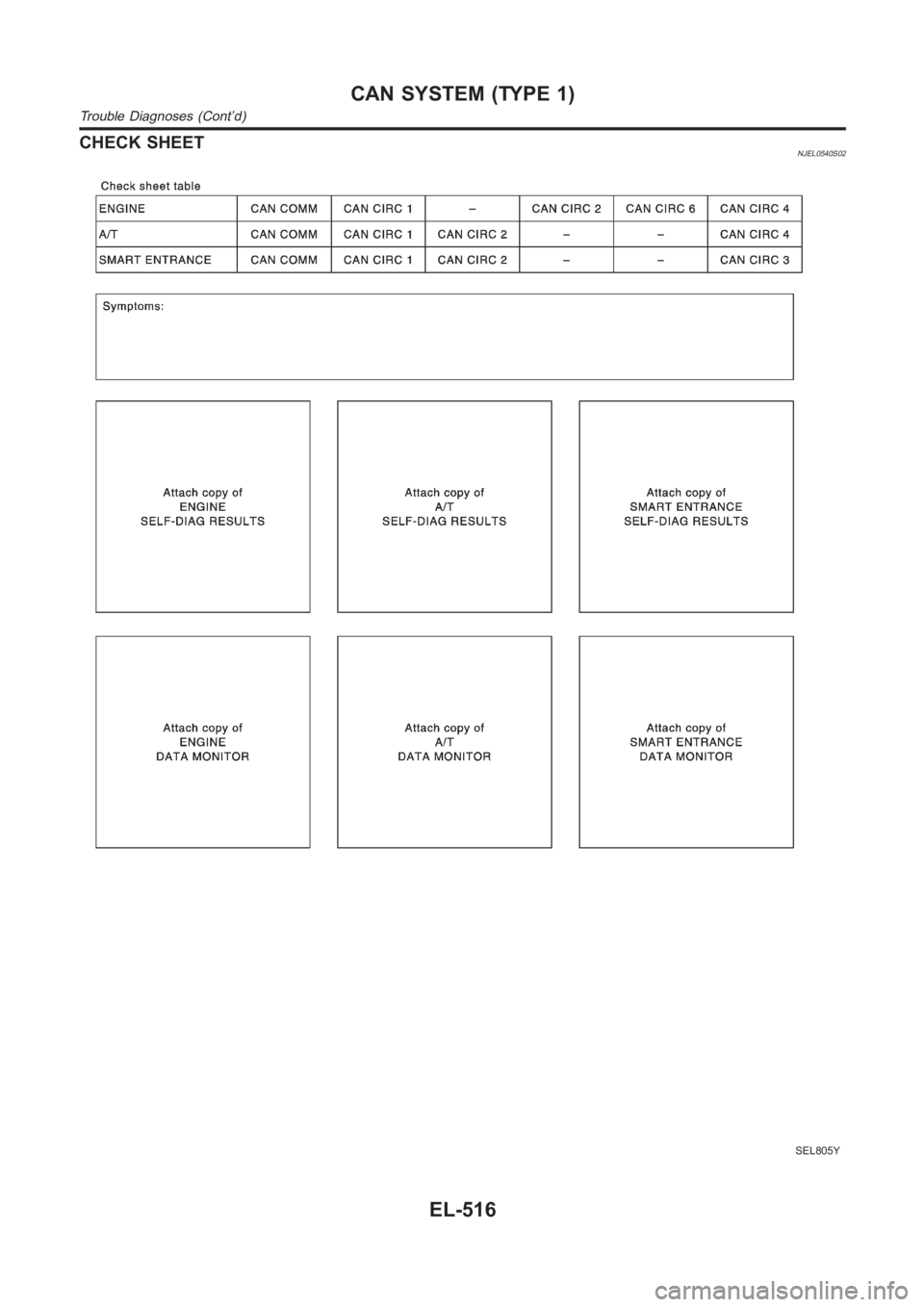
2. Attach the printed sheet of “SELF-DIAG RESULTS” and “DATA MONITOR” ontothe check sheet. Refer
to “CHECK SHEET” (EL-516).
3. Based on the data monitor results, put “v” marks onto the items with “UNKWN” or “NG” in the check sheet
table. Refer to “CHECK SHEET“ (EL-516).
NOTE:
If “NG” is displayed on “CAN COMM” for the diagnosed control unit, replace the control unit.
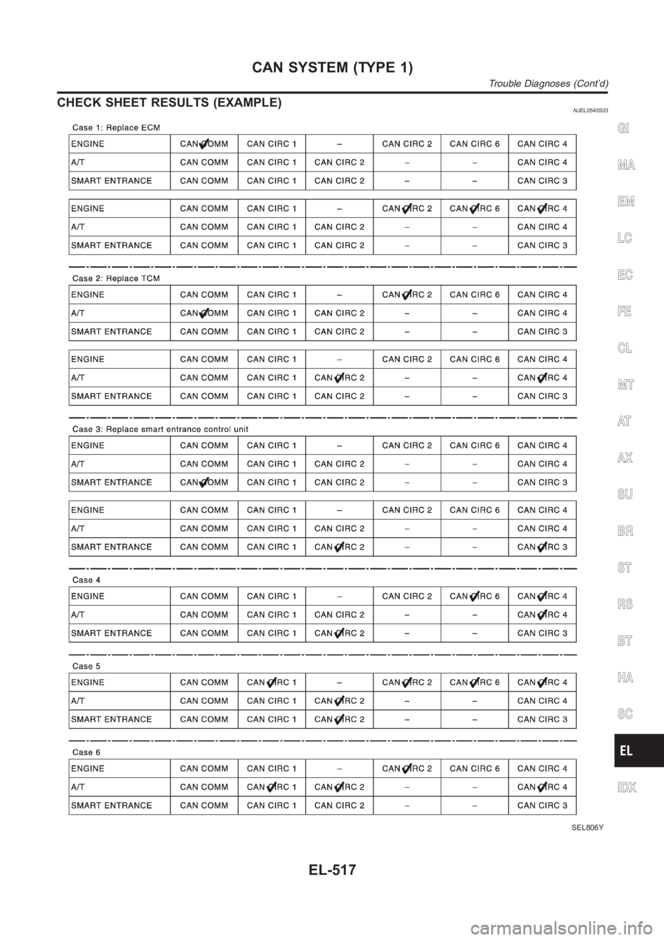
4. According to the check sheet results (example), start inspection. Refer to “CHECK SHEET RESULTS
(EXAMPLE)” (EL-517).GI
MA
EM
LC
EC
FE
CL
MT
AT
AX
SU
BR
ST
RS
BT
HA
SC
IDX
CAN SYSTEM (TYPE 1)
Trouble Diagnoses
EL-515
Page 2852 of 3189
CHECK SHEETNJEL0540S02
SEL805Y
CAN SYSTEM (TYPE 1)
Trouble Diagnoses (Cont’d)
EL-516
Page 2853 of 3189
CHECK SHEET RESULTS (EXAMPLE)NJEL0540S03
SEL806Y
GI
MA
EM
LC
EC
FE
CL
MT
AT
AX
SU
BR
ST
RS
BT
HA
SC
IDX
CAN SYSTEM (TYPE 1)
Trouble Diagnoses (Cont’d)
EL-517
Page 2854 of 3189
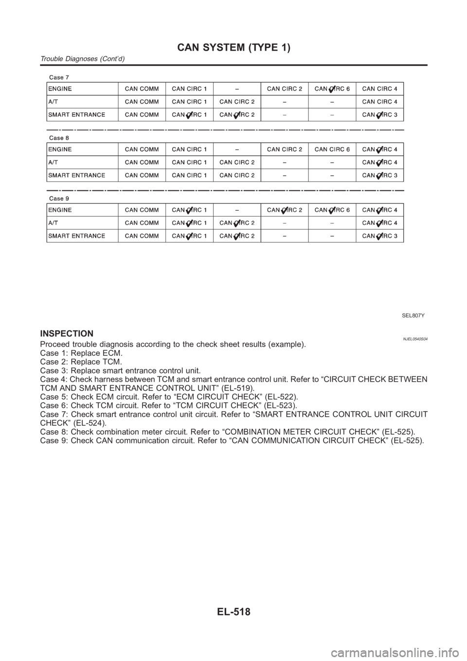
SEL807Y
INSPECTIONNJEL0540S04Proceed trouble diagnosis according to the check sheet results (example).
Case 1: Replace ECM.
Case 2: Replace TCM.
Case 3: Replace smart entrance control unit.
Case 4: Check harness between TCM and smart entrance control unit. Refer to“CIRCUIT CHECK BETWEEN
TCM AND SMART ENTRANCE CONTROL UNIT” (EL-519).
Case 5: Check ECM circuit. Refer to “ECM CIRCUIT CHECK” (EL-522).
Case 6: Check TCM circuit. Refer to “TCM CIRCUIT CHECK” (EL-523).
Case 7: Check smart entrance control unit circuit. Refer to “SMART ENTRANCE CONTROL UNIT CIRCUIT
CHECK” (EL-524).
Case 8: Check combination meter circuit. Refer to “COMBINATION METER CIRCUIT CHECK” (EL-525).
Case 9: Check CAN communication circuit. Refer to “CAN COMMUNICATION CIRCUIT CHECK” (EL-525).
CAN SYSTEM (TYPE 1)
Trouble Diagnoses (Cont’d)
EL-518
Page 2855 of 3189
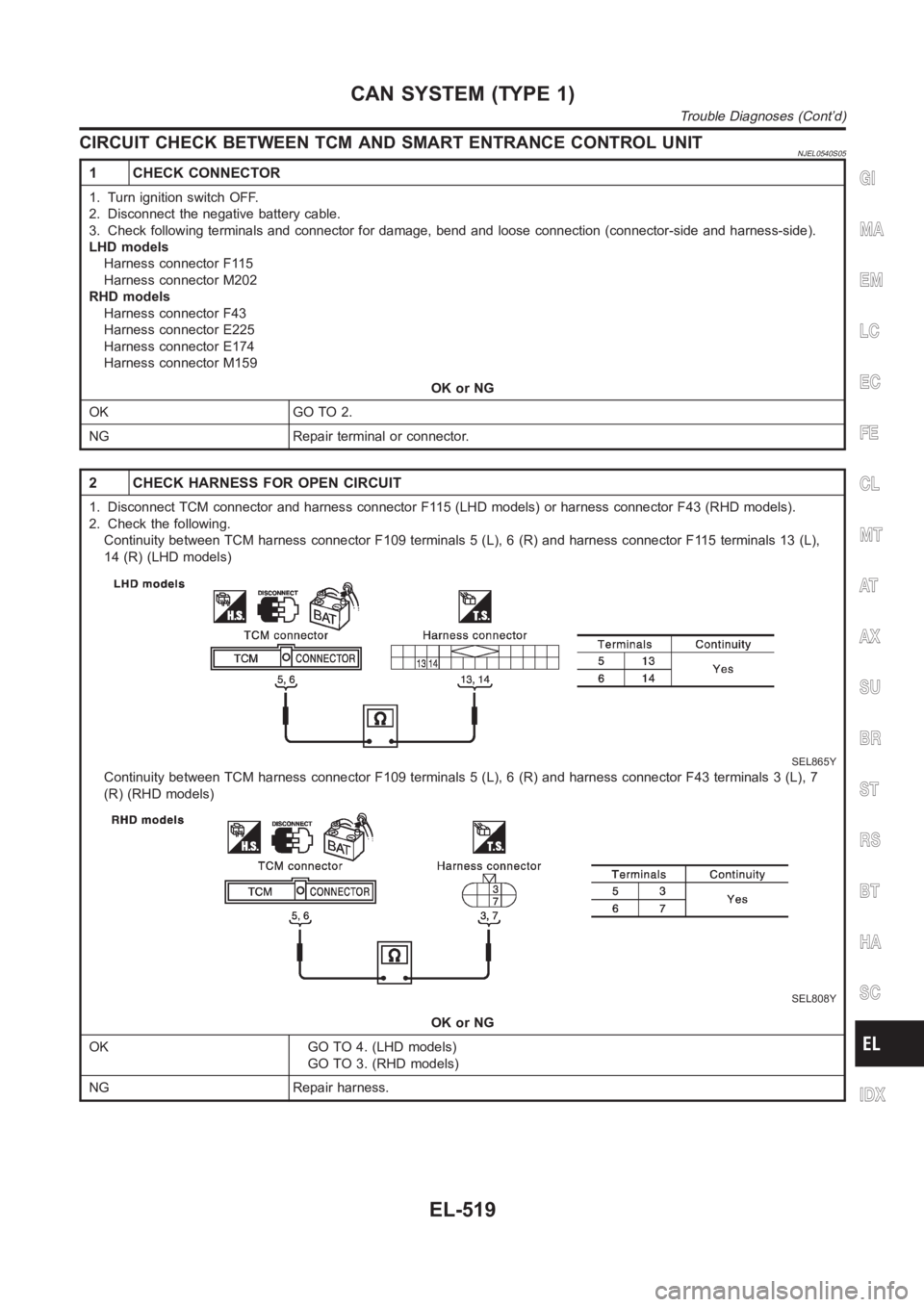
CIRCUIT CHECK BETWEEN TCM AND SMART ENTRANCE CONTROL UNITNJEL0540S05
1 CHECK CONNECTOR
1. Turn ignition switch OFF.
2. Disconnect the negative battery cable.
3. Check following terminals and connector for damage, bend and loose connection (connector-side and harness-side).
LHD models
Harness connector F115
Harness connector M202
RHD models
Harness connector F43
Harness connector E225
Harness connector E174
Harness connector M159
OK or NG
OK GO TO 2.
NG Repair terminal or connector.
2 CHECK HARNESS FOR OPEN CIRCUIT
1. Disconnect TCM connector and harness connector F115 (LHD models) or harness connector F43 (RHD models).
2. Check the following.
Continuity between TCM harness connector F109 terminals 5 (L), 6 (R) and harness connector F115 terminals 13 (L),
14 (R) (LHD models)
SEL865Y
Continuity between TCM harness connector F109 terminals 5 (L), 6 (R) and harness connector F43 terminals 3 (L), 7
(R) (RHD models)
SEL808Y
OK or NG
OK GO TO 4. (LHD models)
GO TO 3. (RHD models)
NG Repair harness.
GI
MA
EM
LC
EC
FE
CL
MT
AT
AX
SU
BR
ST
RS
BT
HA
SC
IDX
CAN SYSTEM (TYPE 1)
Trouble Diagnoses (Cont’d)
EL-519
Page 2856 of 3189
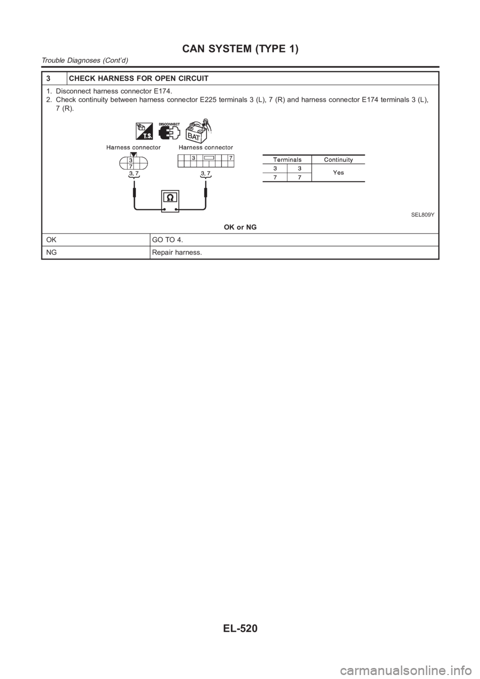
3 CHECK HARNESS FOR OPEN CIRCUIT
1. Disconnect harness connector E174.
2. Check continuity between harness connector E225 terminals 3 (L), 7 (R) and harness connector E174 terminals 3 (L),
7(R).
SEL809Y
OK or NG
OK GO TO 4.
NG Repair harness.
CAN SYSTEM (TYPE 1)
Trouble Diagnoses (Cont’d)
EL-520
Page 2857 of 3189
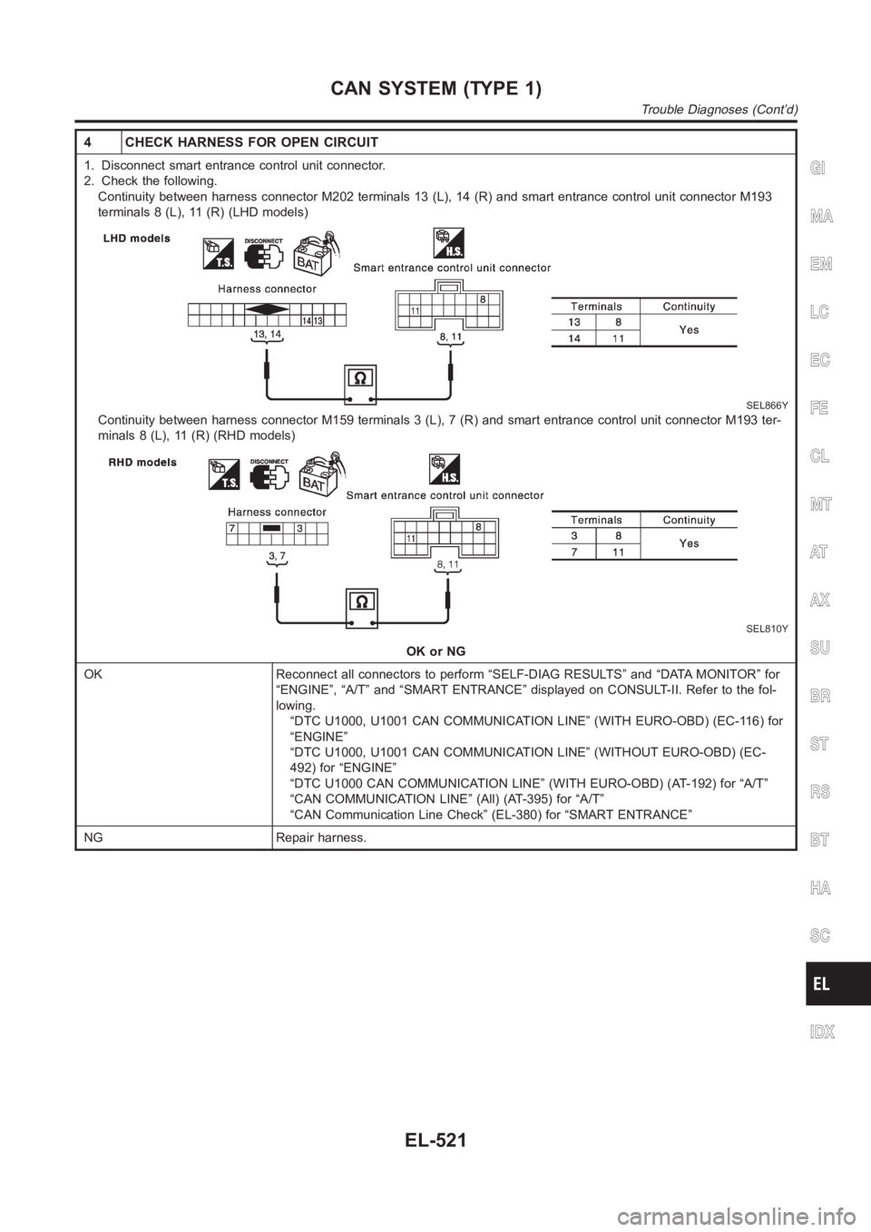
4 CHECK HARNESS FOR OPEN CIRCUIT
1. Disconnect smart entrance control unit connector.
2. Check the following.
Continuity between harness connector M202 terminals 13 (L), 14 (R) and smart entrance control unit connector M193
terminals 8 (L), 11 (R) (LHD models)
SEL866Y
Continuity between harness connector M159 terminals 3 (L), 7 (R) and smartentrance control unit connector M193 ter-
minals 8 (L), 11 (R) (RHD models)
SEL810Y
OK or NG
OK Reconnect all connectors to perform “SELF-DIAG RESULTS” and “DATA MONITOR” for
“ENGINE”, “A/T” and “SMART ENTRANCE” displayed on CONSULT-II. Refer to the fol-
lowing.
“DTC U1000, U1001 CAN COMMUNICATION LINE” (WITH EURO-OBD) (EC-116) for
“ENGINE”
“DTC U1000, U1001 CAN COMMUNICATION LINE” (WITHOUT EURO-OBD) (EC-
492) for “ENGINE”
“DTC U1000 CAN COMMUNICATION LINE” (WITH EURO-OBD) (AT-192) for “A/T”
“CAN COMMUNICATION LINE” (All) (AT-395) for “A/T”
“CAN Communication Line Check” (EL-380) for “SMART ENTRANCE”
NG Repair harness.
GI
MA
EM
LC
EC
FE
CL
MT
AT
AX
SU
BR
ST
RS
BT
HA
SC
IDX
CAN SYSTEM (TYPE 1)
Trouble Diagnoses (Cont’d)
EL-521
Page 2858 of 3189
ECM CIRCUIT CHECK=NJEL0540S06
1 CHECK CONNECTOR
1. Turn ignition switch OFF.
2. Disconnect the negative battery cable.
3. Check the terminals and connector of ECM for damage, bend and loose connection (control module-side and harness-
side).
OK or NG
OK GO TO 2.
NG Repair terminal or connector.
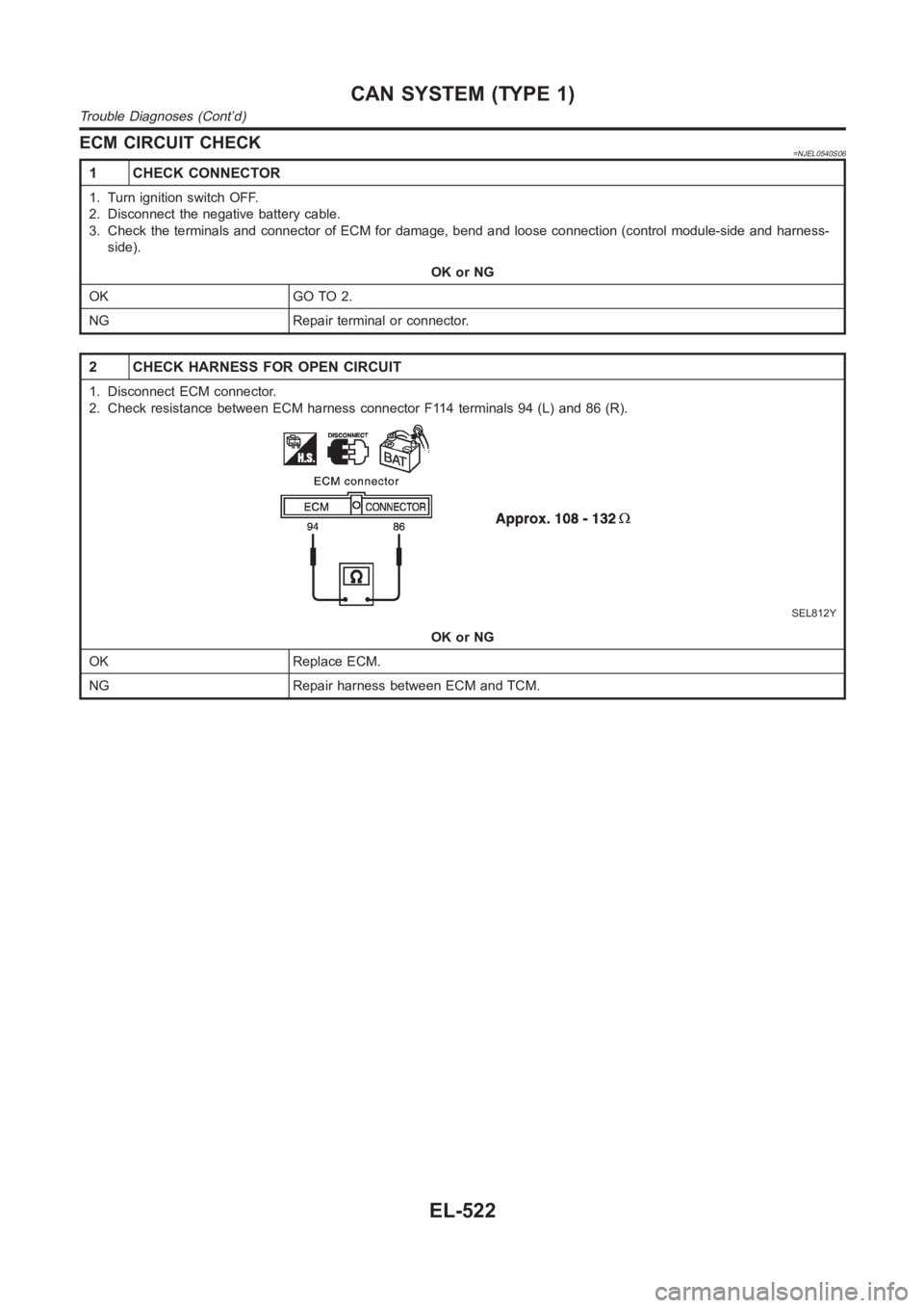
2 CHECK HARNESS FOR OPEN CIRCUIT
1. Disconnect ECM connector.
2. Check resistance between ECM harness connector F114 terminals 94 (L) and86(R).
SEL812Y
OK or NG
OK Replace ECM.
NG Repair harness between ECM and TCM.
CAN SYSTEM (TYPE 1)
Trouble Diagnoses (Cont’d)
EL-522
Page 2859 of 3189
TCM CIRCUIT CHECK=NJEL0540S07
1 CHECK CONNECTOR
1. Turn ignition switch OFF.
2. Disconnect the negative battery cable.
3. Check the terminals and connector of TCM for damage, bend and loose connection (control module-side and harness-
side).
OK or NG
OK GO TO 2.
NG Repair terminal or connector.
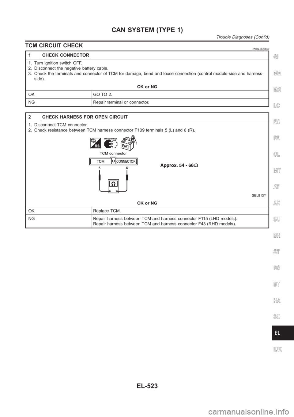
2 CHECK HARNESS FOR OPEN CIRCUIT
1. Disconnect TCM connector.
2. Check resistance between TCM harness connector F109 terminals 5 (L) and6(R).
SEL813Y
OK or NG
OK Replace TCM.
NG Repair harness between TCM and harness connector F115 (LHD models).
Repair harness between TCM and harness connector F43 (RHD models).
GI
MA
EM
LC
EC
FE
CL
MT
AT
AX
SU
BR
ST
RS
BT
HA
SC
IDX
CAN SYSTEM (TYPE 1)
Trouble Diagnoses (Cont’d)
EL-523
Page 2860 of 3189
SMART ENTRANCE CONTROL UNIT CIRCUIT CHECK=NJEL0540S08
1 CHECK CONNECTOR
1. Turn ignition switch OFF.
2. Disconnect the negative battery cable.
3. Check the terminals and connector of smart entrance control unit for damage, bend and loose connection (control unit-
side and harness-side).
OK or NG
OK GO TO 2.
NG Repair terminal or connector.
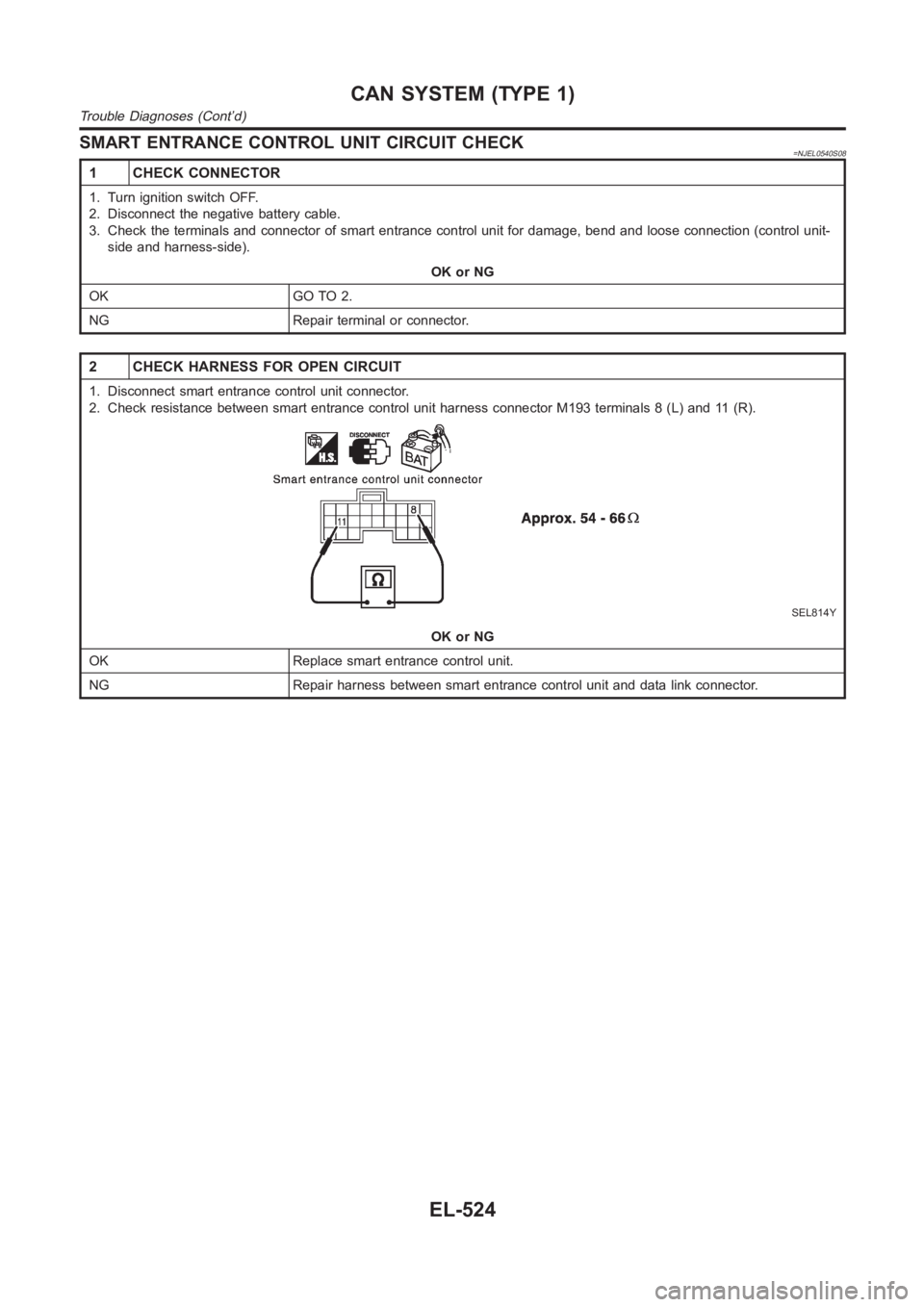
2 CHECK HARNESS FOR OPEN CIRCUIT
1. Disconnect smart entrance control unit connector.
2. Check resistance between smart entrance control unit harness connector M193 terminals 8 (L) and 11 (R).
SEL814Y
OK or NG
OK Replace smart entrance control unit.
NG Repair harness between smart entrance control unit and data link connector.
CAN SYSTEM (TYPE 1)
Trouble Diagnoses (Cont’d)
EL-524
Trending: srs, pressure, gauges, key battery, heating, radio controls, hood open

