NISSAN NAVARA 2005 Repair Workshop Manual
NAVARA 2005
NISSAN
NISSAN
https://www.carmanualsonline.info/img/5/57362/w960_57362-0.png
NISSAN NAVARA 2005 Repair Workshop Manual
Trending: tires, Em-49, oil capacity, bulb, airbag, Engine lubrication system, power steering belt
Page 301 of 3171
REPAIR FOR COMPONENT PARTS
AT-293
D
E
F
G
H
I
J
K
L
MA
B
AT
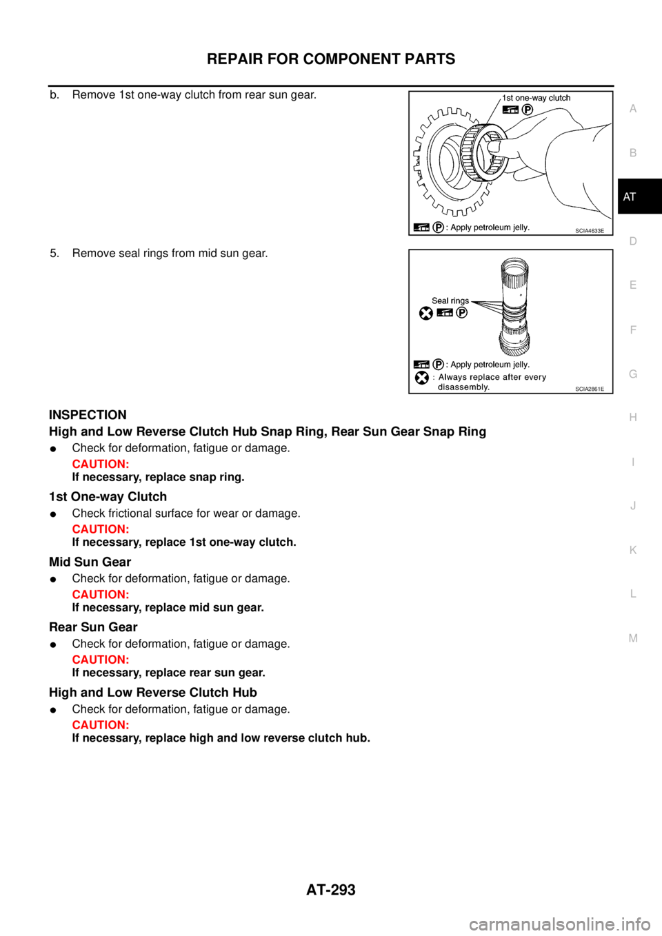
b. Remove 1st one-way clutch from rear sun gear.
5. Remove seal rings from mid sun gear.
INSPECTION
High and Low Reverse Clutch Hub Snap Ring, Rear Sun Gear Snap Ring
lCheck for deformation, fatigue or damage.
CAUTION:
If necessary, replace snap ring.
1st One-way Clutch
lCheck frictional surface for wear or damage.
CAUTION:
If necessary, replace 1st one-way clutch.
Mid Sun Gear
lCheck for deformation, fatigue or damage.
CAUTION:
If necessary, replace mid sun gear.
Rear Sun Gear
lCheck for deformation, fatigue or damage.
CAUTION:
If necessary, replace rear sun gear.
High and Low Reverse Clutch Hub
lCheck for deformation, fatigue or damage.
CAUTION:
If necessary, replace high and low reverse clutch hub.
SCIA4633E
SCIA2861E
Page 302 of 3171
AT-294
REPAIR FOR COMPONENT PARTS
ASSEMBLY
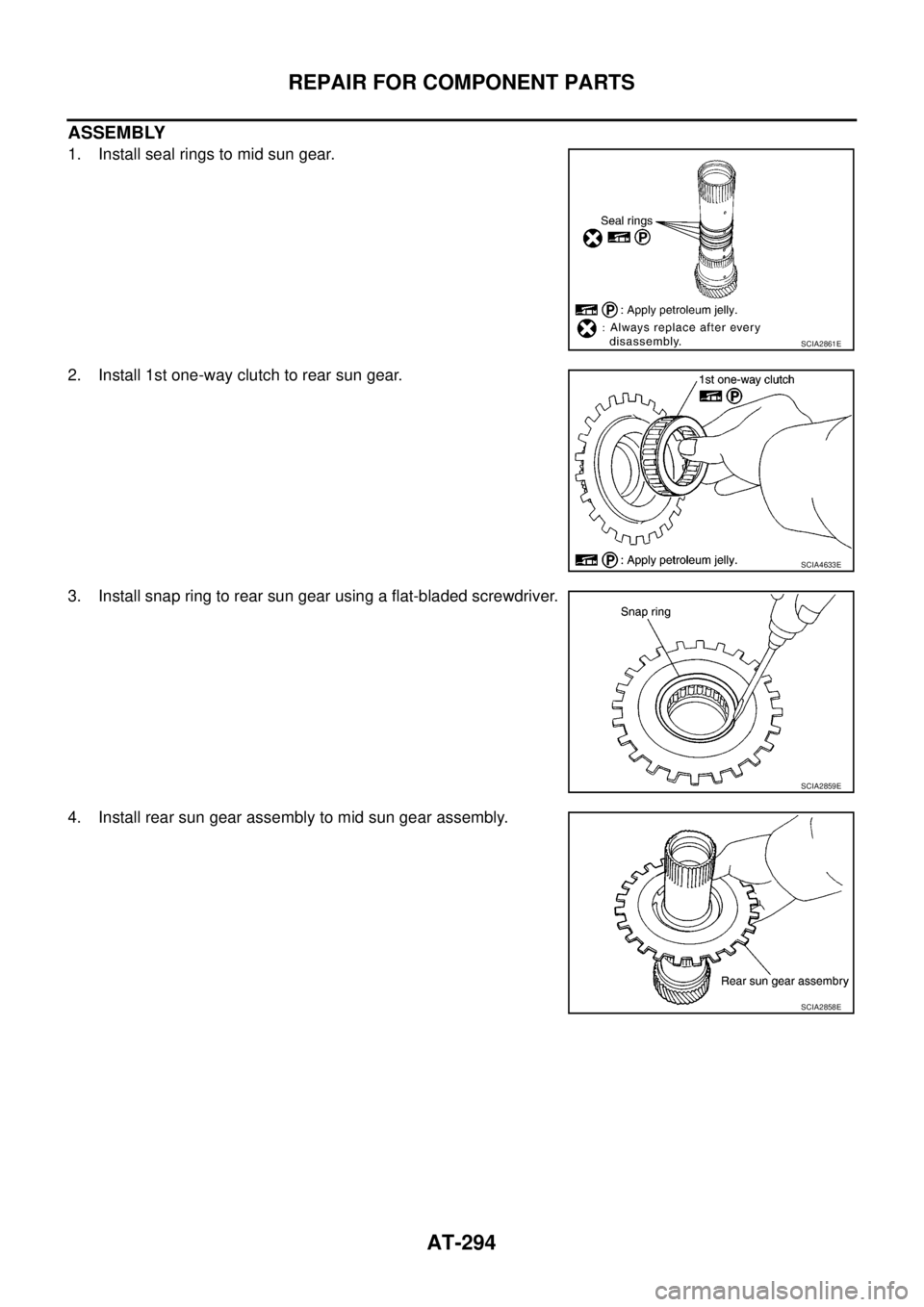
1. Install seal rings to mid sun gear.
2. Install 1st one-way clutch to rear sun gear.
3. Install snap ring to rear sun gear using a flat-bladed screwdriver.
4. Install rear sun gear assembly to mid sun gear assembly.
SCIA2861E
SCIA4633E
SCIA2859E
SCIA2858E
Page 303 of 3171
REPAIR FOR COMPONENT PARTS
AT-295
D
E
F
G
H
I
J
K
L
MA
B
AT
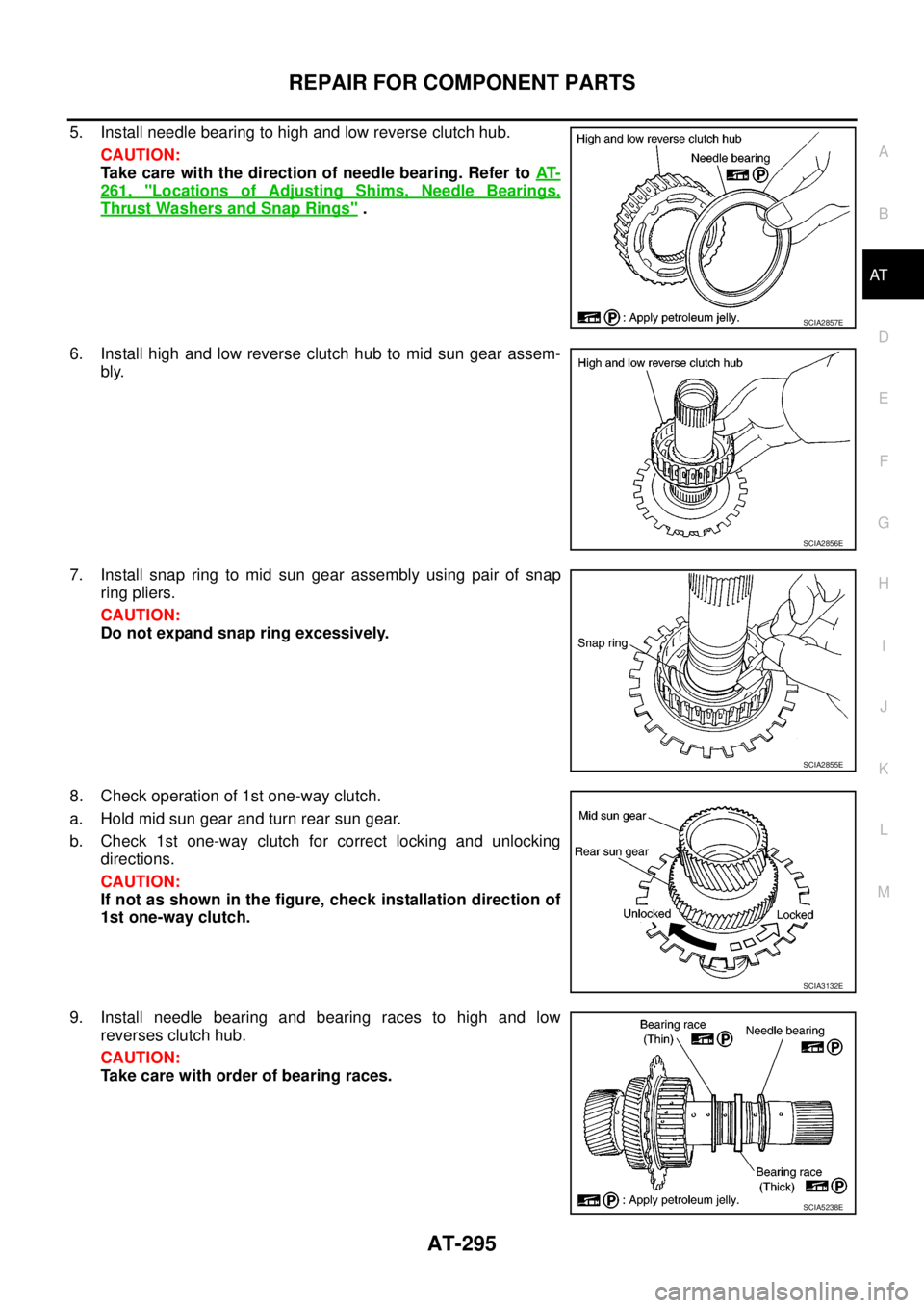
5. Install needle bearing to high and low reverse clutch hub.
CAUTION:
Take care with the direction of needle bearing. Refer toAT-
261, "Locations of Adjusting Shims, Needle Bearings,
Thrust Washers and Snap Rings".
6. Install high and low reverse clutch hub to mid sun gear assem-
bly.
7. Install snap ring to mid sun gear assembly using pair of snap
ring pliers.
CAUTION:
Do not expand snap ring excessively.
8. Check operation of 1st one-way clutch.
a. Hold mid sun gear and turn rear sun gear.
b. Check 1st one-way clutch for correct locking and unlocking
directions.
CAUTION:
If not as shown in the figure, check installation direction of
1st one-way clutch.
9. Install needle bearing and bearing races to high and low
reverses clutch hub.
CAUTION:
Take care with order of bearing races.
SCIA2857E
SCIA2856E
SCIA2855E
SCIA3132E
SCIA5238E
Page 304 of 3171
AT-296
REPAIR FOR COMPONENT PARTS
High and Low Reverse Clutch
ECS00G3J
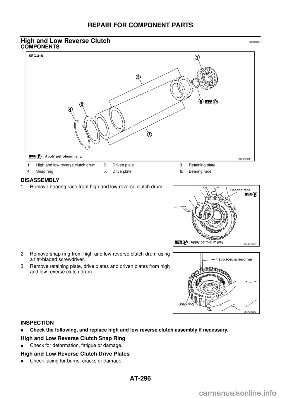
COMPONENTS
DISASSEMBLY
1. Remove bearing race from high and low reverse clutch drum.
2. Remove snap ring from high and low reverse clutch drum using
a flat-bladed screwdriver.
3. Remove retaining plate, drive plates and driven plates from high
and low reverse clutch drum.
INSPECTION
lCheck the following, and replace high and low reverse clutch assembly if necessary.
High and Low Reverse Clutch Snap Ring
lCheck for deformation, fatigue or damage.
High and Low Reverse Clutch Drive Plates
lCheck facing for burns, cracks or damage.
1. High and low reverse clutch drum 2. Driven plate 3. Retaining plate
4. Snap ring 5. Drive plate 6. Bearing race
SCIA5239E
SCIA5240E
SCIA2868E
Page 305 of 3171
REPAIR FOR COMPONENT PARTS
AT-297
D
E
F
G
H
I
J
K
L
MA
B
AT
High and Low Reverse Clutch Retaining Plate and Driven Plates
lCheck facing for burns, cracks or damage.
ASSEMBLY
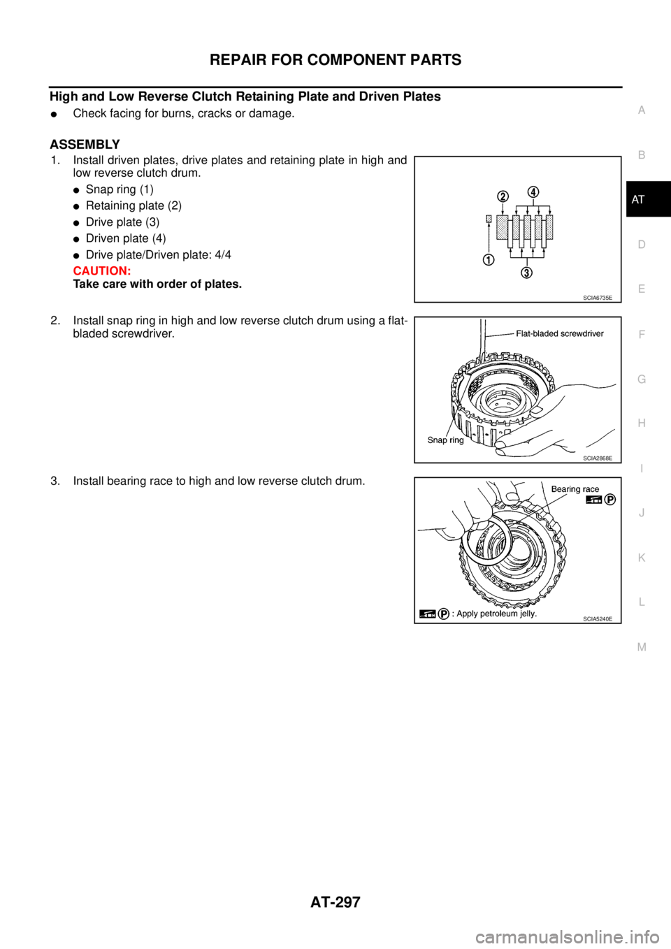
1. Install driven plates, drive plates and retaining plate in high and
low reverse clutch drum.
lSnap ring (1)
lRetaining plate (2)
lDrive plate (3)
lDriven plate (4)
lDrive plate/Driven plate: 4/4
CAUTION:
Take care with order of plates.
2. Install snap ring in high and low reverse clutch drum using a flat-
bladed screwdriver.
3. Install bearing race to high and low reverse clutch drum.
SCIA6735E
SCIA2868E
SCIA5240E
Page 306 of 3171
AT-298
REPAIR FOR COMPONENT PARTS
Direct Clutch
ECS00G3K
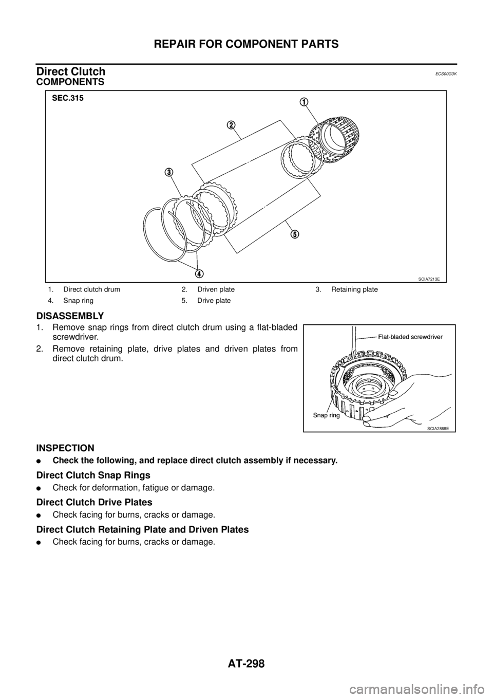
COMPONENTS
DISASSEMBLY
1. Remove snap rings from direct clutch drum using a flat-bladed
screwdriver.
2. Remove retaining plate, drive plates and driven plates from
direct clutch drum.
INSPECTION
lCheck the following, and replace direct clutch assembly if necessary.
Direct Clutch Snap Rings
lCheck for deformation, fatigue or damage.
Direct Clutch Drive Plates
lCheck facing for burns, cracks or damage.
Direct Clutch Retaining Plate and Driven Plates
lCheck facing for burns, cracks or damage.
1. Direct clutch drum 2. Driven plate 3. Retaining plate
4. Snap ring 5. Drive plate
SCIA7213E
SCIA2868E
Page 307 of 3171
REPAIR FOR COMPONENT PARTS
AT-299
D
E
F
G
H
I
J
K
L
MA
B
AT
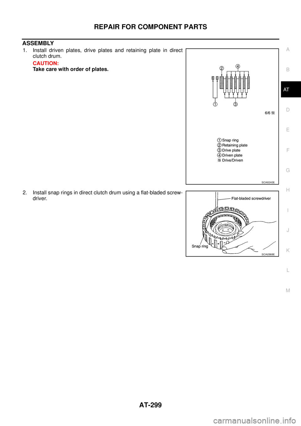
ASSEMBLY
1. Install driven plates, drive plates and retaining plate in direct
clutch drum.
CAUTION:
Take care with order of plates.
2. Install snap rings in direct clutch drum using a flat-bladed screw-
driver.
SCIA5243E
SCIA2868E
Page 308 of 3171
AT-300
ASSEMBLY
ASSEMBLY
PFP:00000
Assembly (1)ECS00G3L
1. As shown in the figure, use a drift [commercial service tool: 22
mm (0.87 in) dia.] to drive manual shaft oil seals into transmis-
sion case until it is flush.
CAUTION:
lApply ATF to manual shaft oil seals.
lDo not reuse manual shaft oil seals.
2. Install detent spring and spacer to transmission case and then
tighten mounting dolts to the specified torque. Refer toAT-251,
"Components".
3. Install manual shaft to transmission case.
4. Install parking rod to manual plate.
SCIA5259E
SCIA5248E
SCIA5716E
SCIA5220E
Page 309 of 3171
ASSEMBLY
AT-301
D
E
F
G
H
I
J
K
L
MA
B
AT
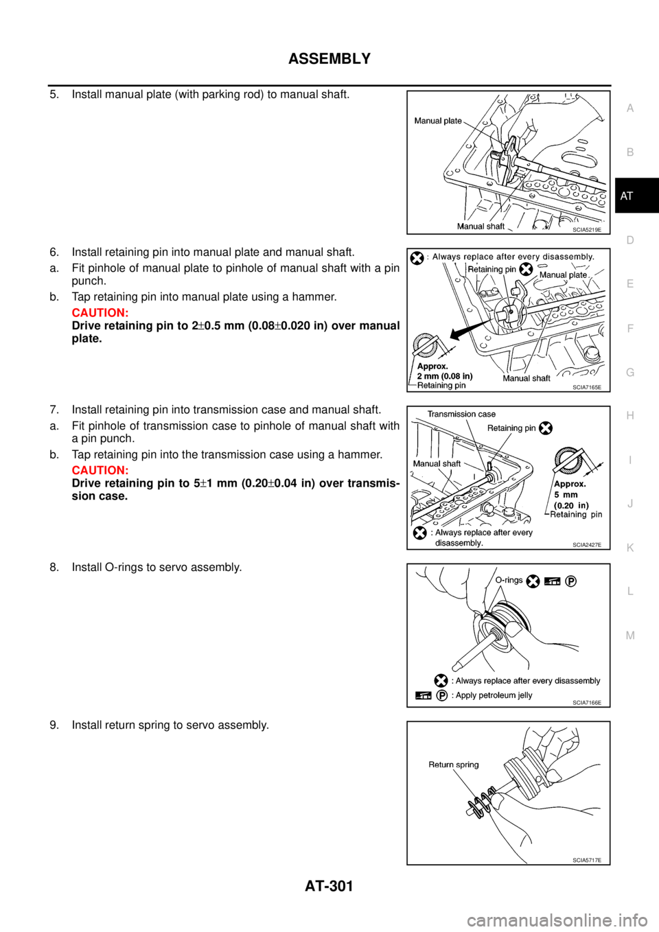
5. Install manual plate (with parking rod) to manual shaft.
6. Install retaining pin into manual plate and manual shaft.
a. Fit pinhole of manual plate to pinhole of manual shaft with a pin
punch.
b. Tap retaining pin into manual plate using a hammer.
CAUTION:
Drive retaining pin to 2±0.5 mm (0.08±0.020 in) over manual
plate.
7. Install retaining pin into transmission case and manual shaft.
a. Fit pinhole of transmission case to pinhole of manual shaft with
a pin punch.
b. Tap retaining pin into the transmission case using a hammer.
CAUTION:
Drive retaining pin to 5±1mm(0.20±0.04 in) over transmis-
sion case.
8. Install O-rings to servo assembly.
9. Install return spring to servo assembly.
SCIA5219E
SCIA7165E
SCIA2427E
SCIA7166E
SCIA5717E
Page 310 of 3171
AT-302
ASSEMBLY
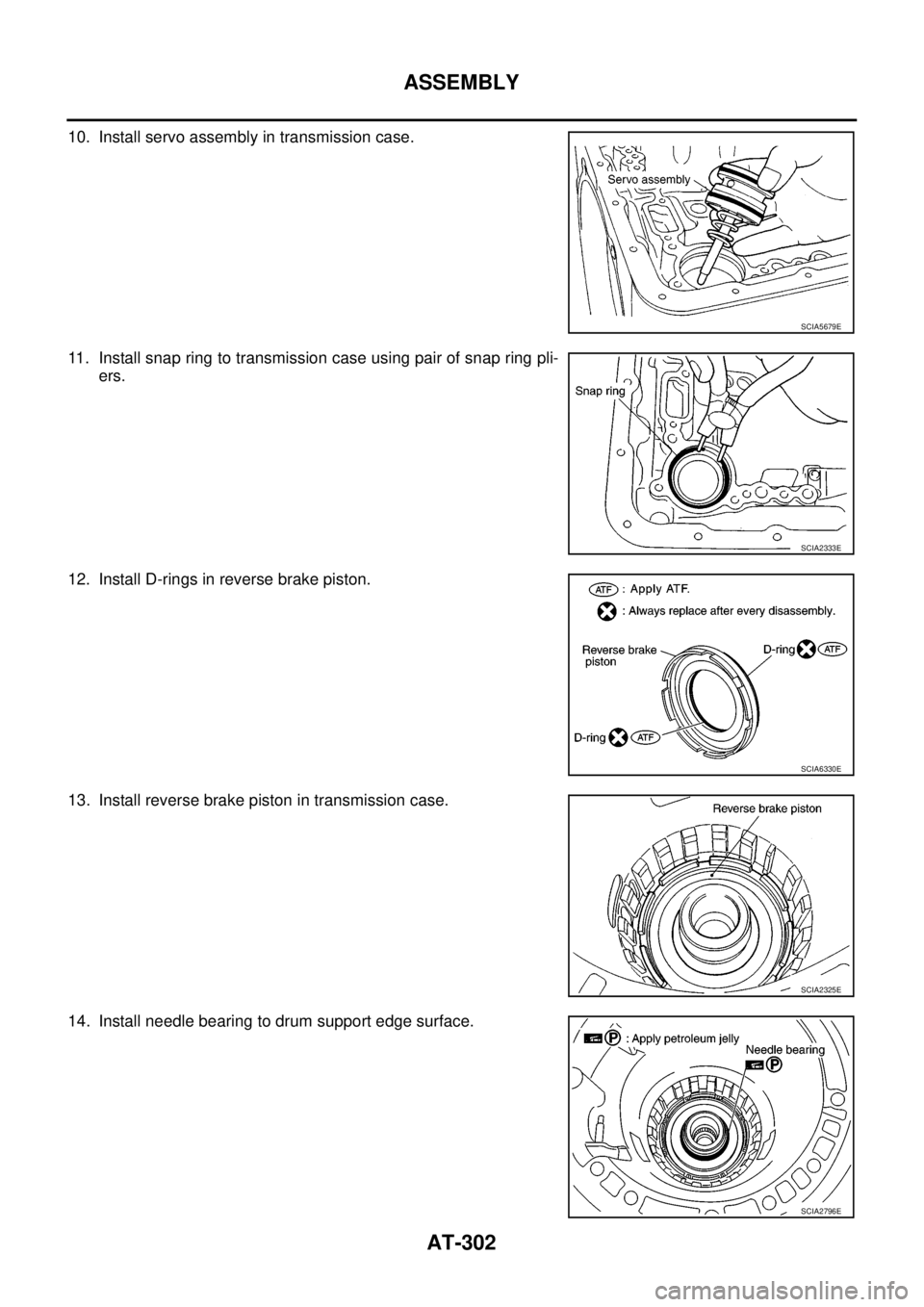
10. Install servo assembly in transmission case.
11. Install snap ring to transmission case using pair of snap ring pli-
ers.
12. Install D-rings in reverse brake piston.
13. Install reverse brake piston in transmission case.
14. Install needle bearing to drum support edge surface.
SCIA5679E
SCIA2333E
SCIA6330E
SCIA2325E
SCIA2796E
Trending: check oil, immobilizer, trunk release, alternator, power steering fluid, boot, run flat
![NISSAN NAVARA 2005 Repair Workshop Manual AT-300
ASSEMBLY
ASSEMBLY
PFP:00000
Assembly (1)ECS00G3L
1. As shown in the figure, use a drift [commercial service tool: 22
mm (0.87 in) dia.] to drive manual shaft oil seals into transmis-
sion case NISSAN NAVARA 2005 Repair Workshop Manual AT-300
ASSEMBLY
ASSEMBLY
PFP:00000
Assembly (1)ECS00G3L
1. As shown in the figure, use a drift [commercial service tool: 22
mm (0.87 in) dia.] to drive manual shaft oil seals into transmis-
sion case](/img/5/57362/w960_57362-307.png)
