sensor NISSAN PATROL 1998 Y61 / 5.G Engine Control Manual Online
[x] Cancel search | Manufacturer: NISSAN, Model Year: 1998, Model line: PATROL, Model: NISSAN PATROL 1998 Y61 / 5.GPages: 192, PDF Size: 4.28 MB
Page 150 of 192

COMPONENT INSPECTION
Crankshaft position sensor (TDC)
1. Disconnect crankshaft position sensor (TDC) harness connec-
tor.
2. Loosen the ®xing bolt of the sensor.
3. Remove the sensor.
4. Visually check the sensor for chipping.
5. Check resistance between terminals
V1andV2.
Resistance: Approximately 0.8 - 1.2 kW
[at 25ÉC (77ÉF)]
If NG, replace crankshaft position sensor (TDC).
SEF620S
SEF697V
TROUBLE DIAGNOSIS FOR ``CRANK POS SEN (TDC)'' (DTC 47)
Crankshaft Position Sensor (TDC) (Cont'd)
EC-148
Page 151 of 192
Governor Cut Circuit
ON BOARD DIAGNOSIS LOGIC
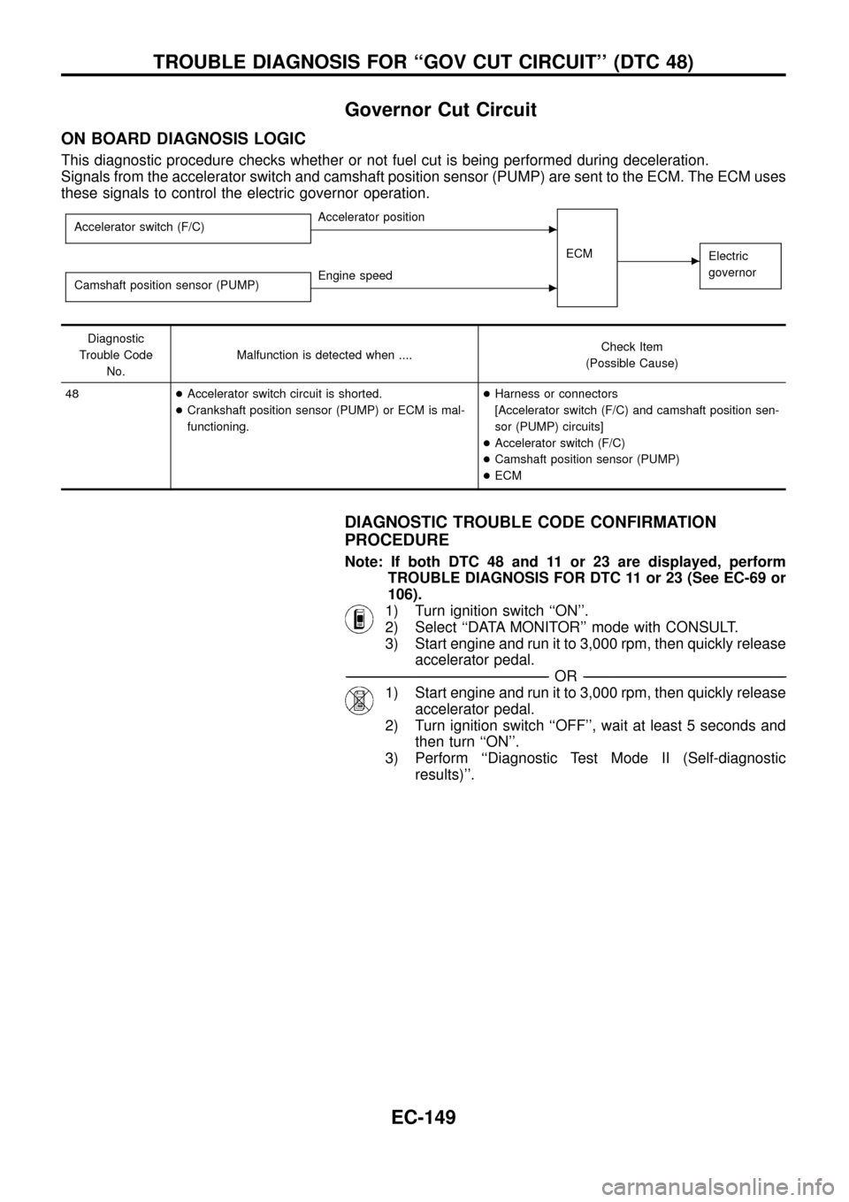
This diagnostic procedure checks whether or not fuel cut is being performed during deceleration.
Signals from the accelerator switch and camshaft position sensor (PUMP) are sent to the ECM. The ECM uses
these signals to control the electric governor operation.
Accelerator switch (F/C)cAccelerator position
ECM
cElectric
governor
Camshaft position sensor (PUMP)cEngine speed
Diagnostic
Trouble Code
No.Malfunction is detected when ....Check Item
(Possible Cause)
48+Accelerator switch circuit is shorted.
+Crankshaft position sensor (PUMP) or ECM is mal-
functioning.+Harness or connectors
[Accelerator switch (F/C) and camshaft position sen-
sor (PUMP) circuits]
+Accelerator switch (F/C)
+Camshaft position sensor (PUMP)
+ECM
DIAGNOSTIC TROUBLE CODE CONFIRMATION
PROCEDURE
Note: If both DTC 48 and 11 or 23 are displayed, perform
TROUBLE DIAGNOSIS FOR DTC 11 or 23 (See EC-69 or
106).
1) Turn ignition switch ``ON''.
2) Select ``DATA MONITOR'' mode with CONSULT.
3) Start engine and run it to 3,000 rpm, then quickly release
accelerator pedal.
-------------------------------------------------------------------------------------------------------------------------------------------------------------------------------------------------------------------------------------------------------OR-------------------------------------------------------------------------------------------------------------------------------------------------------------------------------------------------------------------------------------------------------
1) Start engine and run it to 3,000 rpm, then quickly release
accelerator pedal.
2) Turn ignition switch ``OFF'', wait at least 5 seconds and
then turn ``ON''.
3) Perform ``Diagnostic Test Mode II (Self-diagnostic
results)''.
TROUBLE DIAGNOSIS FOR ``GOV CUT CIRCUIT'' (DTC 48)
EC-149
Page 153 of 192
Glow Control System
SYSTEM DESCRIPTION
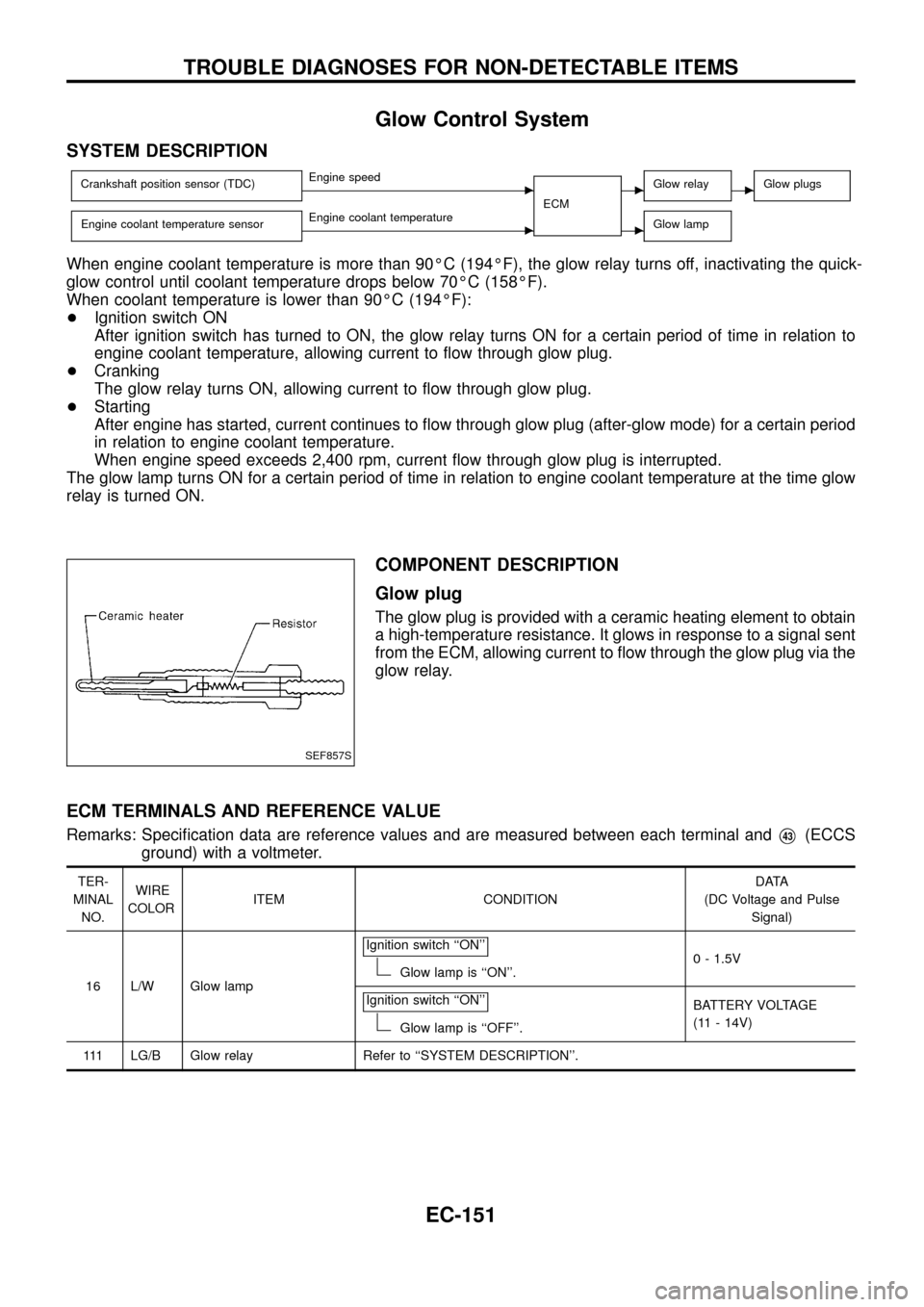
Crankshaft position sensor (TDC)cEngine speed
ECMcGlow relaycGlow plugs
Engine coolant temperature sensorcEngine coolant temperaturecGlow lamp
When engine coolant temperature is more than 90ÉC (194ÉF), the glow relay turns off, inactivating the quick-
glow control until coolant temperature drops below 70ÉC (158ÉF).
When coolant temperature is lower than 90ÉC (194ÉF):
+Ignition switch ON
After ignition switch has turned to ON, the glow relay turns ON for a certain period of time in relation to
engine coolant temperature, allowing current to ¯ow through glow plug.
+Cranking
The glow relay turns ON, allowing current to ¯ow through glow plug.
+Starting
After engine has started, current continues to ¯ow through glow plug (after-glow mode) for a certain period
in relation to engine coolant temperature.
When engine speed exceeds 2,400 rpm, current ¯ow through glow plug is interrupted.
The glow lamp turns ON for a certain period of time in relation to engine coolant temperature at the time glow
relay is turned ON.
COMPONENT DESCRIPTION
Glow plug
The glow plug is provided with a ceramic heating element to obtain
a high-temperature resistance. It glows in response to a signal sent
from the ECM, allowing current to ¯ow through the glow plug via the
glow relay.
ECM TERMINALS AND REFERENCE VALUE
Remarks: Speci®cation data are reference values and are measured between each terminal andV43(ECCS
ground) with a voltmeter.
TER-
MINAL
NO.WIRE
COLORITEM CONDITIONDATA
(DC Voltage and Pulse
Signal)
16 L/W Glow lampIgnition switch ``ON''
Glow lamp is ``ON''.0 - 1.5V
Ignition switch ``ON''
Glow lamp is ``OFF''.BATTERY VOLTAGE
(11 - 14V)
111 LG/B Glow relay Refer to ``SYSTEM DESCRIPTION''.
SEF857S
TROUBLE DIAGNOSES FOR NON-DETECTABLE ITEMS
EC-151
Page 158 of 192
EGRC-Solenoid Valve A, B and Throttle Control
Solenoid Valve
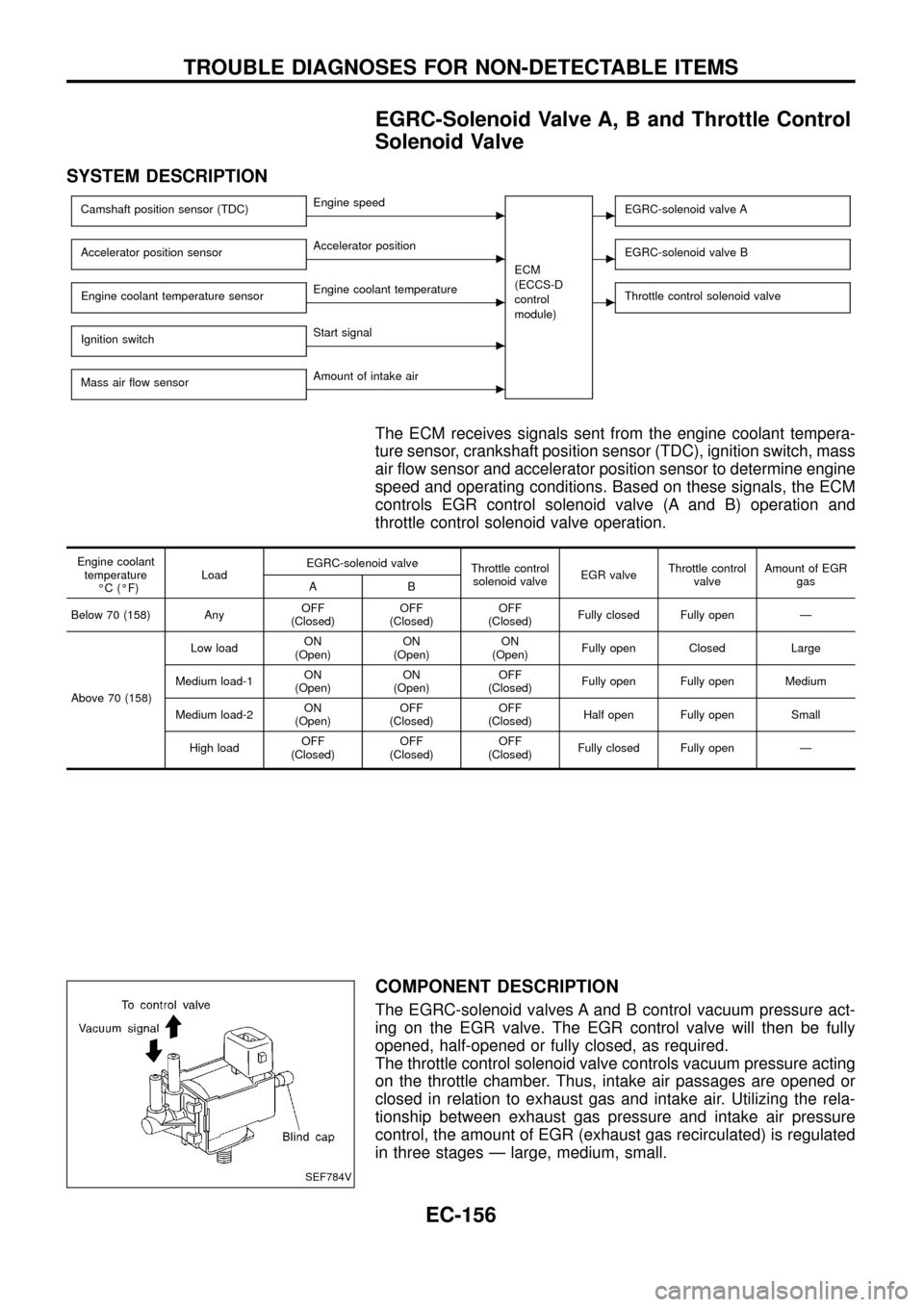
SYSTEM DESCRIPTION
Camshaft position sensor (TDC)cEngine speed
ECM
(ECCS-D
control
module)cEGRC-solenoid valve A
Accelerator position sensorcAccelerator positioncEGRC-solenoid valve B
Engine coolant temperature sensorcEngine coolant temperaturecThrottle control solenoid valve
Ignition switchcStart signal
Mass air ¯ow sensor
cAmount of intake air
The ECM receives signals sent from the engine coolant tempera-
ture sensor, crankshaft position sensor (TDC), ignition switch, mass
air ¯ow sensor and accelerator position sensor to determine engine
speed and operating conditions. Based on these signals, the ECM
controls EGR control solenoid valve (A and B) operation and
throttle control solenoid valve operation.
Engine coolant
temperature
ÉC (ÉF)LoadEGRC-solenoid valve
Throttle control
solenoid valveEGR valveThrottle control
valveAmount of EGR
gas
AB
Below 70 (158) AnyOFF
(Closed)OFF
(Closed)OFF
(Closed)Fully closed Fully open Ð
Above 70 (158)Low loadON
(Open)ON
(Open)ON
(Open)Fully open Closed Large
Medium load-1ON
(Open)ON
(Open)OFF
(Closed)Fully open Fully open Medium
Medium load-2ON
(Open)OFF
(Closed)OFF
(Closed)Half open Fully open Small
High loadOFF
(Closed)OFF
(Closed)OFF
(Closed)Fully closed Fully open Ð
COMPONENT DESCRIPTION
The EGRC-solenoid valves A and B control vacuum pressure act-
ing on the EGR valve. The EGR control valve will then be fully
opened, half-opened or fully closed, as required.
The throttle control solenoid valve controls vacuum pressure acting
on the throttle chamber. Thus, intake air passages are opened or
closed in relation to exhaust gas and intake air. Utilizing the rela-
tionship between exhaust gas pressure and intake air pressure
control, the amount of EGR (exhaust gas recirculated) is regulated
in three stages Ð large, medium, small.
SEF784V
TROUBLE DIAGNOSES FOR NON-DETECTABLE ITEMS
EC-156
Page 171 of 192

COMPONENT INSPECTION
Accelerator position switch
1. Disconnect accelerator position switch harness connector.
2. Check continuity between terminals
V5andV6.
Conditions Continuity
Accelerator pedal released Yes
Accelerator pedal depressed No
3. Check continuity between terminalsV4andV5.
Conditions Continuity
Accelerator pedal released No
Accelerator pedal fully depressed Yes
If NG, replace accelerator pedal assembly.
CAUTION:
If accelerator position sensor or ECM connector is
disconnected, perform the following procedures:
Select ``OFF ACCEL PO SIG'' in ``ACTIVE TEST'' mode.
Touch CLEAR.
-------------------------------------------------------------------------------------------------------------------------------------------------------------------------------------------------------------------------------------------------------OR-------------------------------------------------------------------------------------------------------------------------------------------------------------------------------------------------------------------------------------------------------
Start and warm up engine. After engine has warmed up,
idle for 10 minutes.
SEF709V
TROUBLE DIAGNOSES FOR NON-DETECTABLE ITEMS
Accelerator Position Switch (Cont'd)
EC-169
Page 180 of 192
Charge Air Cooler Fan Control
SYSTEM DESCRIPTION
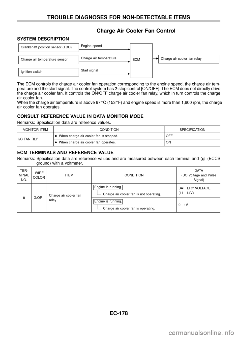
Crankshaft position sensor (TDC)cEngine speed
ECM
cCharge air cooler fan relayCharge air temperature sensorcCharge air temperature
Ignition switch
cStart signal
The ECM controls the charge air cooler fan operation corresponding to the engine speed, the charge air tem-
perature and the start signal. The control system has 2-step control [ON/OFF]. The ECM does not directly drive
the charge air cooler fan. It controls the ON/OFF charge air cooler fan relay, which in turn controls the charge
air cooler fan.
When the charge air temperature is above 67ÉC (153ÉF) and engine speed is more than 1,600 rpm, the charge
air cooler fan operates.
CONSULT REFERENCE VALUE IN DATA MONITOR MODE
Remarks: Speci®cation data are reference values.
MONITOR ITEM CONDITION SPECIFICATION
I/C FAN RLY+When charge air cooler fan is stopped. OFF
+When charge air cooler fan operates. ON
ECM TERMINALS AND REFERENCE VALUE
Remarks: Speci®cation data are reference values and are measured between each terminal andV43(ECCS
ground) with a voltmeter.
TER-
MINAL
NO.WIRE
COLORITEM CONDITIONDATA
(DC Voltage and Pulse
Signal)
8 G/ORCharge air cooler fan
relayEngine is running.
Charge air cooler fan is not operating.BATTERY VOLTAGE
(11 - 14V)
Engine is running.
Charge air cooler fan is operating.0-1V
TROUBLE DIAGNOSES FOR NON-DETECTABLE ITEMS
EC-178
Page 182 of 192
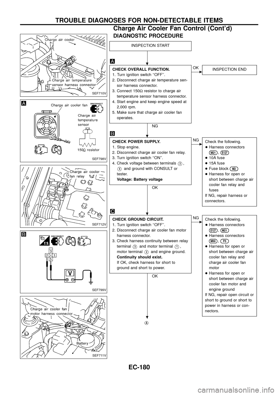
DIAGNOSTIC PROCEDURE
INSPECTION START
CHECK OVERALL FUNCTION.
1. Turn ignition switch ``OFF''.
2. Disconnect charge air temperature sen-
sor harness connector.
3. Connect 150Wresistor to charge air
temperature sensor harness connector.
4. Start engine and keep engine speed at
2,000 rpm.
5. Make sure that charge air cooler fan
operates.
NG
cOK
INSPECTION END
CHECK POWER SUPPLY.
1. Stop engine.
2. Disconnect charge air cooler fan relay.
3. Turn ignition switch ``ON''.
4. Check voltage between terminals
V2,
V5and ground with CONSULT or
tester.
Voltage: Battery voltage
OK
cNG
Check the following.
+Harness connectors
M21,E127
+10A fuse
+15A fuse
+Fuse block
M2
+Harness for open or
short between charge air
cooler fan relay and
fuses
If NG, repair harness or
connectors.
CHECK GROUND CIRCUIT.
1. Turn ignition switch ``OFF''.
2. Disconnect charge air cooler fan motor
harness connector.
3. Check harness continuity between relay
terminal
V3and motor terminalV1,
motor terminal
V2and engine ground.
Continuity should exist.
If OK, check harness for short to
ground and short to power.
OK
cNG
Check the following.
+Harness connectors
E127,M21
+Harness connectors
M50,F5
+Harness for open or
short between charge air
cooler fan relay and
charge air cooler fan
motor
+Harness for open or
short between charge air
cooler fan motor and
engine ground
If NG, repair open circuit or
short to ground or short to
power in harness or con-
nectors.
jA
SEF710V
SEF798V
SEF712V
SEF799V
SEF711V
.
.
.
.
TROUBLE DIAGNOSES FOR NON-DETECTABLE ITEMS
Charge Air Cooler Fan Control (Cont'd)
EC-180
Page 191 of 192
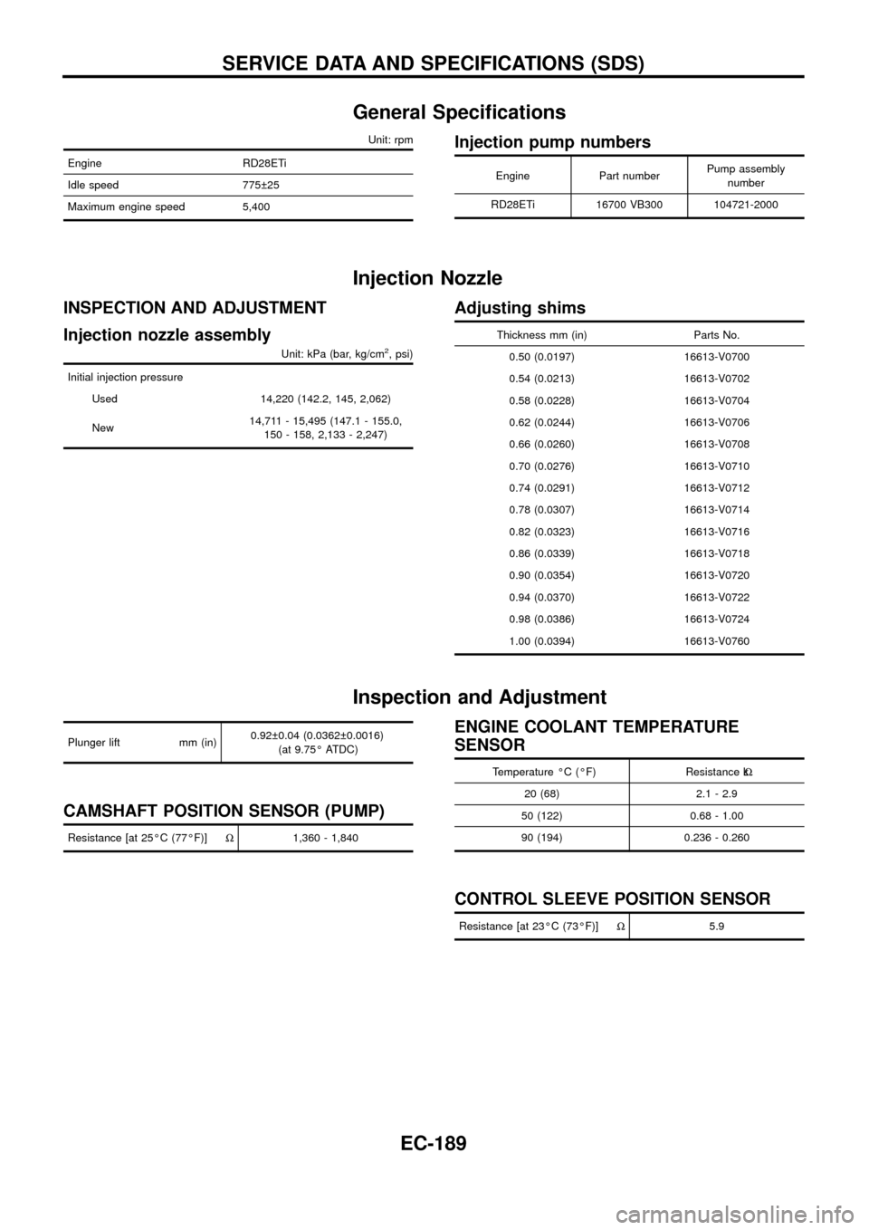
General Speci®cations
Unit: rpm
Engine RD28ETi
Idle speed 775 25
Maximum engine speed 5,400
Injection pump numbers
Engine Part numberPump assembly
number
RD28ETi 16700 VB300 104721-2000
Injection Nozzle
INSPECTION AND ADJUSTMENT
Injection nozzle assembly
Unit: kPa (bar, kg/cm2, psi)
Initial injection pressure
Used 14,220 (142.2, 145, 2,062)
New14,711 - 15,495 (147.1 - 155.0,
150 - 158, 2,133 - 2,247)
Adjusting shims
Thickness mm (in) Parts No.
0.50 (0.0197) 16613-V0700
0.54 (0.0213) 16613-V0702
0.58 (0.0228) 16613-V0704
0.62 (0.0244) 16613-V0706
0.66 (0.0260) 16613-V0708
0.70 (0.0276) 16613-V0710
0.74 (0.0291) 16613-V0712
0.78 (0.0307) 16613-V0714
0.82 (0.0323) 16613-V0716
0.86 (0.0339) 16613-V0718
0.90 (0.0354) 16613-V0720
0.94 (0.0370) 16613-V0722
0.98 (0.0386) 16613-V0724
1.00 (0.0394) 16613-V0760
Inspection and Adjustment
Plunger lift mm (in)0.92 0.04 (0.0362 0.0016)
(at 9.75É ATDC)
CAMSHAFT POSITION SENSOR (PUMP)
Resistance [at 25ÉC (77ÉF)]W1,360 - 1,840
ENGINE COOLANT TEMPERATURE
SENSOR
Temperature ÉC (ÉF) Resistance kW
20 (68) 2.1 - 2.9
50 (122) 0.68 - 1.00
90 (194) 0.236 - 0.260
CONTROL SLEEVE POSITION SENSOR
Resistance [at 23ÉC (73ÉF)]W5.9
SERVICE DATA AND SPECIFICATIONS (SDS)
EC-189
Page 192 of 192
![NISSAN PATROL 1998 Y61 / 5.G Engine Control Manual Online ADJUSTMENT RESISTOR
Resistance [at 25ÉC (77ÉF)] kW0.2 - 15.0
INJECTION TIMING CONTROL VALVE
Resistance [at 20ÉC (68ÉF)]WApproximately 11
ELECTRIC GOVERNOR
Resistance [at 23ÉC (73ÉF)]W0.68
CRANKS NISSAN PATROL 1998 Y61 / 5.G Engine Control Manual Online ADJUSTMENT RESISTOR
Resistance [at 25ÉC (77ÉF)] kW0.2 - 15.0
INJECTION TIMING CONTROL VALVE
Resistance [at 20ÉC (68ÉF)]WApproximately 11
ELECTRIC GOVERNOR
Resistance [at 23ÉC (73ÉF)]W0.68
CRANKS](/img/5/617/w960_617-191.png)
ADJUSTMENT RESISTOR
Resistance [at 25ÉC (77ÉF)] kW0.2 - 15.0
INJECTION TIMING CONTROL VALVE
Resistance [at 20ÉC (68ÉF)]WApproximately 11
ELECTRIC GOVERNOR
Resistance [at 23ÉC (73ÉF)]W0.68
CRANKSHAFT POSITION SENSOR (TDC)
Resistance [at 25ÉC (77ÉF)] kWApproximately 0.8 - 1.2
GLOW PLUG
Resistance [at 25ÉC (77ÉF)]W0.8
ACCELERATOR POSITION SENSOR
Throttle valve conditionsResistance kW
[at 25ÉC (77ÉF)]
Completely closed Approximately 0.5
Partially open 0.5 - 4
Completely open Approximately 4
FUEL TEMPERATURE SENSOR
Temperature ÉC (ÉF) Resistance kW
þ20 (þ4) 13.67 - 16.37
20 (68) 2.306 - 2.568
60 (140) 0.538 - 0.624
80 (176) 0.289 - 0.344
SERVICE DATA AND SPECIFICATIONS (SDS)
Inspection and Adjustment (Cont'd)
EC-190