NISSAN PICK-UP 1998 Repair Manual
Manufacturer: NISSAN, Model Year: 1998, Model line: PICK-UP, Model: NISSAN PICK-UP 1998Pages: 1659, PDF Size: 53.39 MB
Page 1581 of 1659
Nominal cylinder head height:
98.8 - 99.0 mm (3.890 - 3.898 in)
CAMSHAFT VISUAL CHECK
Check camshaft for scratches, seizure and wear.
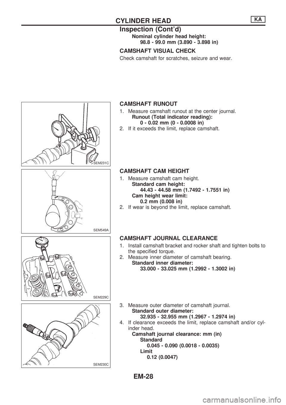
CAMSHAFT RUNOUT
1. Measure camshaft runout at the center journal.
Runout (Total indicator reading):
0 - 0.02 mm (0 - 0.0008 in)
2. If it exceeds the limit, replace camshaft.
CAMSHAFT CAM HEIGHT
1. Measure camshaft cam height.
Standard cam height:
44.43 - 44.58 mm (1.7492 - 1.7551 in)
Cam height wear limit:
0.2 mm (0.008 in)
2. If wear is beyond the limit, replace camshaft.
CAMSHAFT JOURNAL CLEARANCE
1. Install camshaft bracket and rocker shaft and tighten bolts to
the specified torque.
2. Measure inner diameter of camshaft bearing.
Standard inner diameter:
33.000 - 33.025 mm (1.2992 - 1.3002 in)
3. Measure outer diameter of camshaft journal.
Standard outer diameter:
32.935 - 32.955 mm (1.2967 - 1.2974 in)
4. If clearance exceeds the limit, replace camshaft and/or cyl-
inder head.
Camshaft journal clearance: mm (in)
Standard
0.045 - 0.090 (0.0018 - 0.0035)
Limit
0.12 (0.0047)
SEM231C.SEM231C
SEM549A
SEM229C
SEM230C
CYLINDER HEADKA
Inspection (Cont'd)
EM-28
Page 1582 of 1659
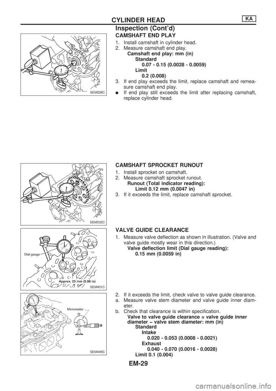
CAMSHAFT END PLAY
1. Install camshaft in cylinder head.
2. Measure camshaft end play.
Camshaft end play: mm (in)
Standard
0.07 - 0.15 (0.0028 - 0.0059)
Limit
0.2 (0.008)
3. If end play exceeds the limit, replace camshaft and remea-
sure camshaft end play.
lIf end play still exceeds the limit after replacing camshaft,
replace cylinder head.
CAMSHAFT SPROCKET RUNOUT
1. Install sprocket on camshaft.
2. Measure camshaft sprocket runout.
Runout (Total indicator reading):
Limit 0.12 mm (0.0047 in)
3. If it exceeds the limit, replace camshaft sprocket.
VALVE GUIDE CLEARANCE
1. Measure valve deflection as shown in illustration. (Valve and
valve guide mostly wear in this direction.)
Valve deflection limit (Dial gauge reading):
0.15 mm (0.0059 in)
2. If it exceeds the limit, check valve to valve guide clearance.
a. Measure valve stem diameter and valve guide inner diam-
eter.
b. Check that clearance is within specification.
Valve to valve guide clearance = valve guide inner
diameter þ valve stem diameter: mm (in)
Standard
Intake
0.020 - 0.053 (0.0008 - 0.0021)
Exhaust
0.040 - 0.070 (0.0016 - 0.0028)
Limit 0.1 (0.004)
SEM228C
SEM232C.SEM232C
SEM451C
SEM449C
CYLINDER HEADKA
Inspection (Cont'd)
EM-29
Page 1583 of 1659
c. If it exceeds the limit, replace valve and remeasure clear-
ance.
lIf clearance still exceeds the limit after replacing valve,
replace the valve guide.
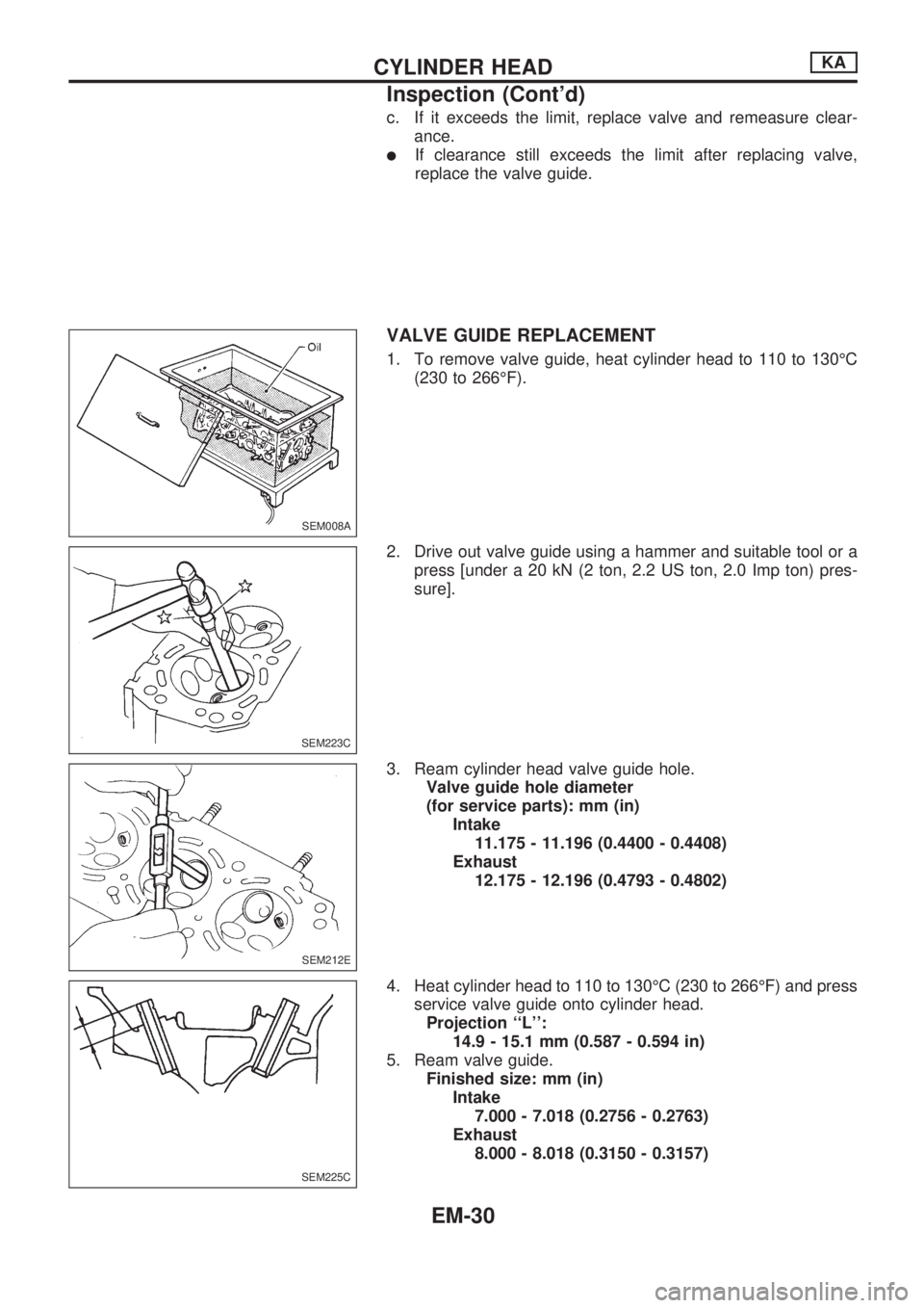
VALVE GUIDE REPLACEMENT
1. To remove valve guide, heat cylinder head to 110 to 130ÉC
(230 to 266ÉF).
2. Drive out valve guide using a hammer and suitable tool or a
press [under a 20 kN (2 ton, 2.2 US ton, 2.0 Imp ton) pres-
sure].
3. Ream cylinder head valve guide hole.
Valve guide hole diameter
(for service parts): mm (in)
Intake
11.175 - 11.196 (0.4400 - 0.4408)
Exhaust
12.175 - 12.196 (0.4793 - 0.4802)
4. Heat cylinder head to 110 to 130ÉC (230 to 266ÉF) and press
service valve guide onto cylinder head.
Projection ``L'':
14.9 - 15.1 mm (0.587 - 0.594 in)
5. Ream valve guide.
Finished size: mm (in)
Intake
7.000 - 7.018 (0.2756 - 0.2763)
Exhaust
8.000 - 8.018 (0.3150 - 0.3157)
SEM008A
SEM223C
SEM212E
SEM225C
CYLINDER HEADKA
Inspection (Cont'd)
EM-30
Page 1584 of 1659
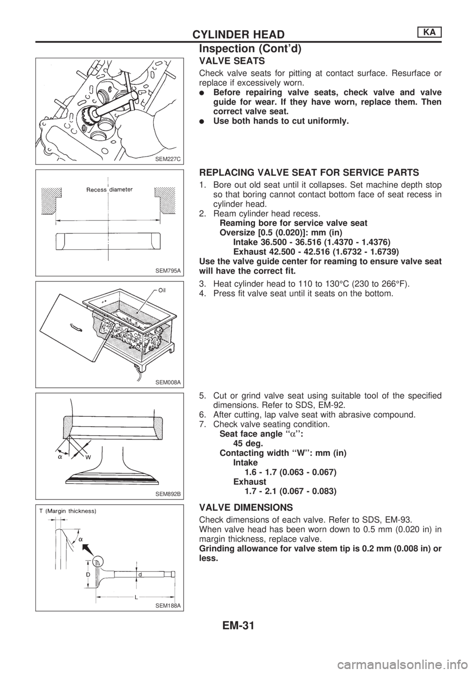
VALVE SEATS
Check valve seats for pitting at contact surface. Resurface or
replace if excessively worn.
lBefore repairing valve seats, check valve and valve
guide for wear. If they have worn, replace them. Then
correct valve seat.
lUse both hands to cut uniformly.
REPLACING VALVE SEAT FOR SERVICE PARTS
1. Bore out old seat until it collapses. Set machine depth stop
so that boring cannot contact bottom face of seat recess in
cylinder head.
2. Ream cylinder head recess.
Reaming bore for service valve seat
Oversize [0.5 (0.020)]: mm (in)
Intake 36.500 - 36.516 (1.4370 - 1.4376)
Exhaust 42.500 - 42.516 (1.6732 - 1.6739)
Use the valve guide center for reaming to ensure valve seat
will have the correct fit.
3. Heat cylinder head to 110 to 130ÉC (230 to 266ÉF).
4. Press fit valve seat until it seats on the bottom.
5. Cut or grind valve seat using suitable tool of the specified
dimensions. Refer to SDS, EM-92.
6. After cutting, lap valve seat with abrasive compound.
7. Check valve seating condition.
Seat face angle ``a'':
45 deg.
Contacting width ``W'': mm (in)
Intake
1.6 - 1.7 (0.063 - 0.067)
Exhaust
1.7 - 2.1 (0.067 - 0.083)
VALVE DIMENSIONS
Check dimensions of each valve. Refer to SDS, EM-93.
When valve head has been worn down to 0.5 mm (0.020 in) in
margin thickness, replace valve.
Grinding allowance for valve stem tip is 0.2 mm (0.008 in) or
less.
SEM227C
SEM795A
SEM008A
SEM892B
SEM188A
CYLINDER HEADKA
Inspection (Cont'd)
EM-31
Page 1585 of 1659
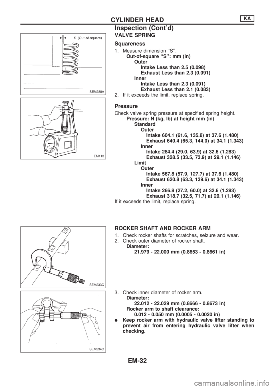
VALVE SPRING
Squareness
1. Measure dimension ``S''.
Out-of-square ``S'': mm (in)
Outer
Intake Less than 2.5 (0.098)
Exhaust Less than 2.3 (0.091)
Inner
Intake Less than 2.3 (0.091)
Exhaust Less than 2.1 (0.083)
2. If it exceeds the limit, replace spring.
Pressure
Check valve spring pressure at specified spring height.
Pressure: N (kg, lb) at height mm (in)
Standard
Outer
Intake 604.1 (61.6, 135.8) at 37.6 (1.480)
Exhaust 640.4 (65.3, 144.0) at 34.1 (1.343)
Inner
Intake 284.4 (29.0, 63.9) at 32.6 (1.283)
Exhaust 328.5 (33.5, 73.9) at 29.1 (1.146)
Limit
Outer
Intake 567.8 (57.9, 127.7) at 37.6 (1.480)
Exhaust 620.8 (63.3, 139.6) at 34.1 (1.343)
Inner
Intake 266.8 (27.2, 60.0) at 32.6 (1.283)
Exhaust 318.7 (32.5, 71.7) at 29.1 (1.146)
If it exceeds the limit, replace spring.
ROCKER SHAFT AND ROCKER ARM
1. Check rocker shafts for scratches, seizure and wear.
2. Check outer diameter of rocker shaft.
Diameter:
21.979 - 22.000 mm (0.8653 - 0.8661 in)
3. Check inner diameter of rocker arm.
Diameter:
22.012 - 22.029 mm (0.8666 - 0.8673 in)
Rocker arm to shaft clearance:
0.012 - 0.050 mm (0.0005 - 0.0020 in)
lKeep rocker arm with hydraulic valve lifter standing to
prevent air from entering hydraulic valve lifter when
checking.
SEM288A
EM113
SEM233C
SEM234C
CYLINDER HEADKA
Inspection (Cont'd)
EM-32
Page 1586 of 1659
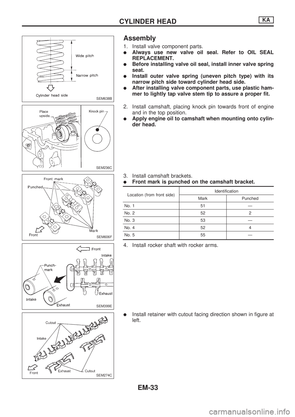
Assembly
1. Install valve component parts.
lAlways use new valve oil seal. Refer to OIL SEAL
REPLACEMENT.
lBefore installing valve oil seal, install inner valve spring
seat.
lInstall outer valve spring (uneven pitch type) with its
narrow pitch side toward cylinder head side.
lAfter installing valve component parts, use plastic ham-
mer to lightly tap valve stem tip to assure a proper fit.
2. Install camshaft, placing knock pin towards front of engine
and in the top position.
lApply engine oil to camshaft when mounting onto cylin-
der head.
3. Install camshaft brackets.
lFront mark is punched on the camshaft bracket.
Location (from front side)Identification
Mark Punched
No. 1 51 Ð
No. 2 52 2
No. 3 53 Ð
No. 4 52 4
No. 5 55 Ð
4. Install rocker shaft with rocker arms.
lInstall retainer with cutout facing direction shown in figure at
left.
SEM638B
SEM236C
SEM606F
SEM399E
SEM274C
CYLINDER HEADKA
EM-33
Page 1587 of 1659
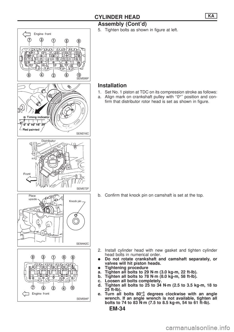
5. Tighten bolts as shown in figure at left.
Installation
1. Set No. 1 piston at TDC on its compression stroke as follows:
a. Align mark on crankshaft pulley with ``0É'' position and con-
firm that distributor rotor head is set as shown in figure.
b. Confirm that knock pin on camshaft is set at the top.
2. Install cylinder head with new gasket and tighten cylinder
head bolts in numerical order.
lDo not rotate crankshaft and camshaft separately, or
valves will hit piston heads.
lTightening procedure
a. Tighten all bolts to 29 N´m (3.0 kg-m, 22 ft-lb).
b. Tighten all bolts to 78 N´m (8.0 kg-m, 58 ft-lb).
c. Loosen all bolts completely.
d. Tighten all bolts to 25 to 34 N´m (2.5 to 3.5 kg-m, 18 to
25 ft-lb).
e. Turn all bolts 80
+5
þ0degrees clockwise with an angle
wrench. If an angle wrench is not available, tighten all
bolts to 74 to 83 N´m (7.5 to 8.5 kg-m, 54 to 61 ft-lb).
SEM599F
SEM216C
SEM572F
SEM442C
SEM594F
CYLINDER HEADKA
Assembly (Cont'd)
EM-34
Page 1588 of 1659
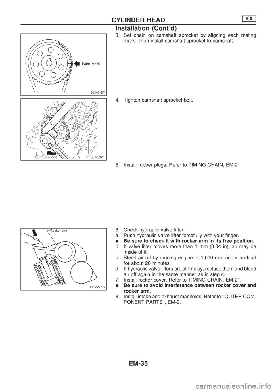
3. Set chain on camshaft sprocket by aligning each mating
mark. Then install camshaft sprocket to camshaft.
4. Tighten camshaft sprocket bolt.
5. Install rubber plugs. Refer to TIMING CHAIN, EM-21.
6. Check hydraulic valve lifter.
a. Push hydraulic valve lifter forcefully with your finger.
lBe sure to check it with rocker arm in its free position.
b. If valve lifter moves more than 1 mm (0.04 in), air may be
inside of it.
c. Bleed air off by running engine at 1,000 rpm under no-load
for about 20 minutes.
d. If hydraulic valve lifters are still noisy, replace them and bleed
air off again in the same manner as in step c.
7. Install rocker cover. Refer to TIMING CHAIN, EM-21.
lBe sure to avoid interference between rocker cover and
rocker arm.
8. Install intake and exhaust manifolds. Refer to ``OUTER COM-
PONENT PARTS'', EM-9.
SEM612F
SEM592F
SEM275C
CYLINDER HEADKA
Installation (Cont'd)
EM-35
Page 1589 of 1659
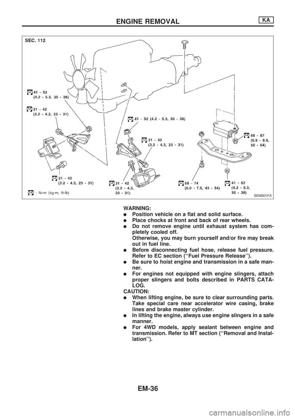
WARNING:
lPosition vehicle on a flat and solid surface.
lPlace chocks at front and back of rear wheels.
lDo not remove engine until exhaust system has com-
pletely cooled off.
Otherwise, you may burn yourself and/or fire may break
out in fuel line.
lBefore disconnecting fuel hose, release fuel pressure.
Refer to EC section (``Fuel Pressure Release'').
lBe sure to hoist engine and transmission in a safe man-
ner.
lFor engines not equipped with engine slingers, attach
proper slingers and bolts described in PARTS CATA-
LOG.
CAUTION:
lWhen lifting engine, be sure to clear surrounding parts.
Take special care near accelerator wire casing, brake
lines and brake master cylinder.
lIn lifting the engine, always use engine slingers in a safe
manner.
lFor 4WD models, apply sealant between engine and
transmission. Refer to MT section (``Removal and Instal-
lation'').
SEM601FA
ENGINE REMOVALKA
EM-36
Page 1590 of 1659
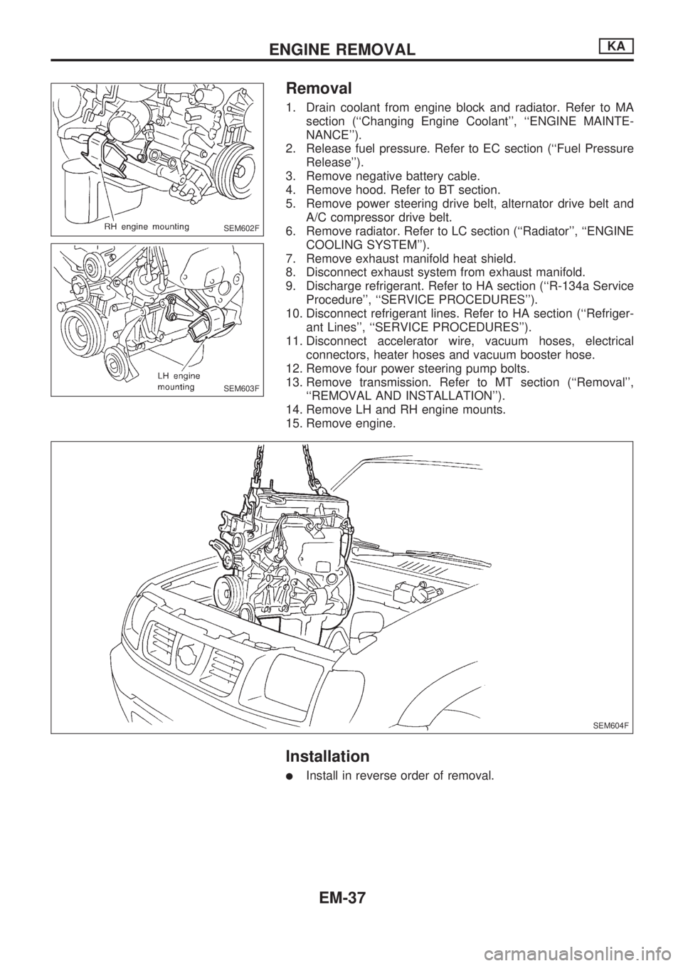
Removal
1. Drain coolant from engine block and radiator. Refer to MA
section (``Changing Engine Coolant'', ``ENGINE MAINTE-
NANCE'').
2. Release fuel pressure. Refer to EC section (``Fuel Pressure
Release'').
3. Remove negative battery cable.
4. Remove hood. Refer to BT section.
5. Remove power steering drive belt, alternator drive belt and
A/C compressor drive belt.
6. Remove radiator. Refer to LC section (``Radiator'', ``ENGINE
COOLING SYSTEM'').
7. Remove exhaust manifold heat shield.
8. Disconnect exhaust system from exhaust manifold.
9. Discharge refrigerant. Refer to HA section (``R-134a Service
Procedure'', ``SERVICE PROCEDURES'').
10. Disconnect refrigerant lines. Refer to HA section (``Refriger-
ant Lines'', ``SERVICE PROCEDURES'').
11. Disconnect accelerator wire, vacuum hoses, electrical
connectors, heater hoses and vacuum booster hose.
12. Remove four power steering pump bolts.
13. Remove transmission. Refer to MT section (``Removal'',
``REMOVAL AND INSTALLATION'').
14. Remove LH and RH engine mounts.
15. Remove engine.
Installation
lInstall in reverse order of removal.
SEM602F
SEM603F
SEM604F
ENGINE REMOVALKA
EM-37