NISSAN PICK-UP 1998 Repair Manual
PICK-UP 1998
NISSAN
NISSAN
https://www.carmanualsonline.info/img/5/57374/w960_57374-0.png
NISSAN PICK-UP 1998 Repair Manual
Trending: cooling, open hood, oil pressure, low beam, fuse box diagram, turn signal bulb, suspension
Page 1561 of 1659
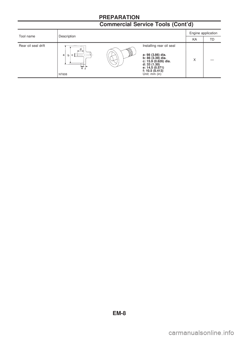
Tool name DescriptionEngine application
KA TD
Rear oil seal drift
NT608
Installing rear oil seal
XÐ
a: 98 (3.86) dia.
b: 86 (3.39) dia.
c: 15.9 (0.626) dia.
d: 33 (1.30)
e: 14.5 (0.571)
f: 10.5 (0.413)
Unit: mm (in)
PREPARATION
Commercial Service Tools (Cont'd)
EM-8
Page 1562 of 1659
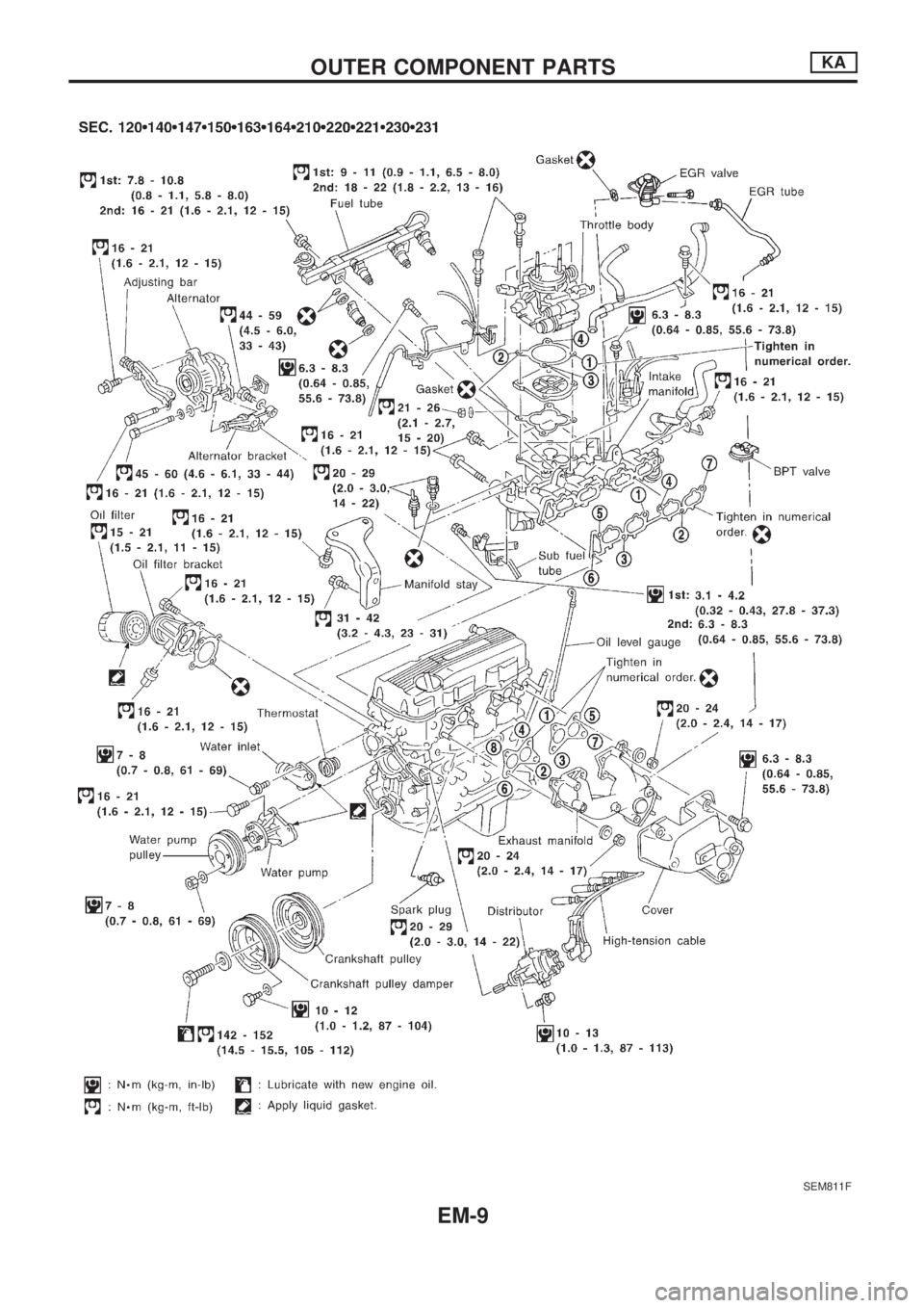
SEM811F
OUTER COMPONENT PARTSKA
EM-9
Page 1563 of 1659
Measurement of Compression Pressure
1. Warm up engine.
2. Turn ignition switch OFF.
3. Release fuel pressure.
Refer to EC section (``Fuel Pressure Release'', ``BASIC SER-
VICE PROCEDURE'').
4. Remove all spark plugs.
5. Disconnect distributor center cable.
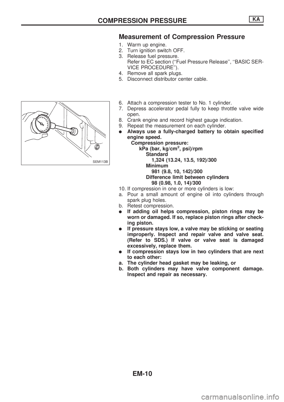
6. Attach a compression tester to No. 1 cylinder.
7. Depress accelerator pedal fully to keep throttle valve wide
open.
8. Crank engine and record highest gauge indication.
9. Repeat the measurement on each cylinder.
lAlways use a fully-charged battery to obtain specified
engine speed.
Compression pressure:
kPa (bar, kg/cm
2, psi)/rpm
Standard
1,324 (13.24, 13.5, 192)/300
Minimum
981 (9.8, 10, 142)/300
Difference limit between cylinders
98 (0.98, 1.0, 14)/300
10. If compression in one or more cylinders is low:
a. Pour a small amount of engine oil into cylinders through
spark plug holes.
b. Retest compression.
lIf adding oil helps compression, piston rings may be
worn or damaged. If so, replace piston rings after check-
ing piston.
lIf pressure stays low, a valve may be sticking or seating
improperly. Inspect and repair valve and valve seat.
(Refer to SDS.) If valve or valve seat is damaged
excessively, replace them.
lIf compression stays low in two cylinders that are next
to each other:
a. The cylinder head gasket may be leaking, or
b. Both cylinders may have valve component damage.
Inspect and repair as necessary.
SEM113B
COMPRESSION PRESSUREKA
EM-10
Page 1564 of 1659
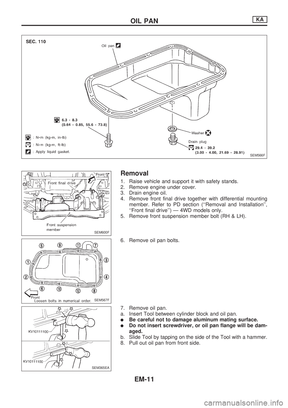
Removal
1. Raise vehicle and support it with safety stands.
2. Remove engine under cover.
3. Drain engine oil.
4. Remove front final drive together with differential mounting
member. Refer to PD section (``Removal and Installation'',
``Front final drive'') Ð 4WD models only.
5. Remove front suspension member bolt (RH & LH).
6. Remove oil pan bolts.
7. Remove oil pan.
a. Insert Tool between cylinder block and oil pan.
lBe careful not to damage aluminum mating surface.
lDo not insert screwdriver, or oil pan flange will be dam-
aged.
b. Slide Tool by tapping on the side of the Tool with a hammer.
8. Pull out oil pan from front side.
SEM566F
SEM600F
SEM567F
SEM365EA
OIL PANKA
EM-11
Page 1565 of 1659
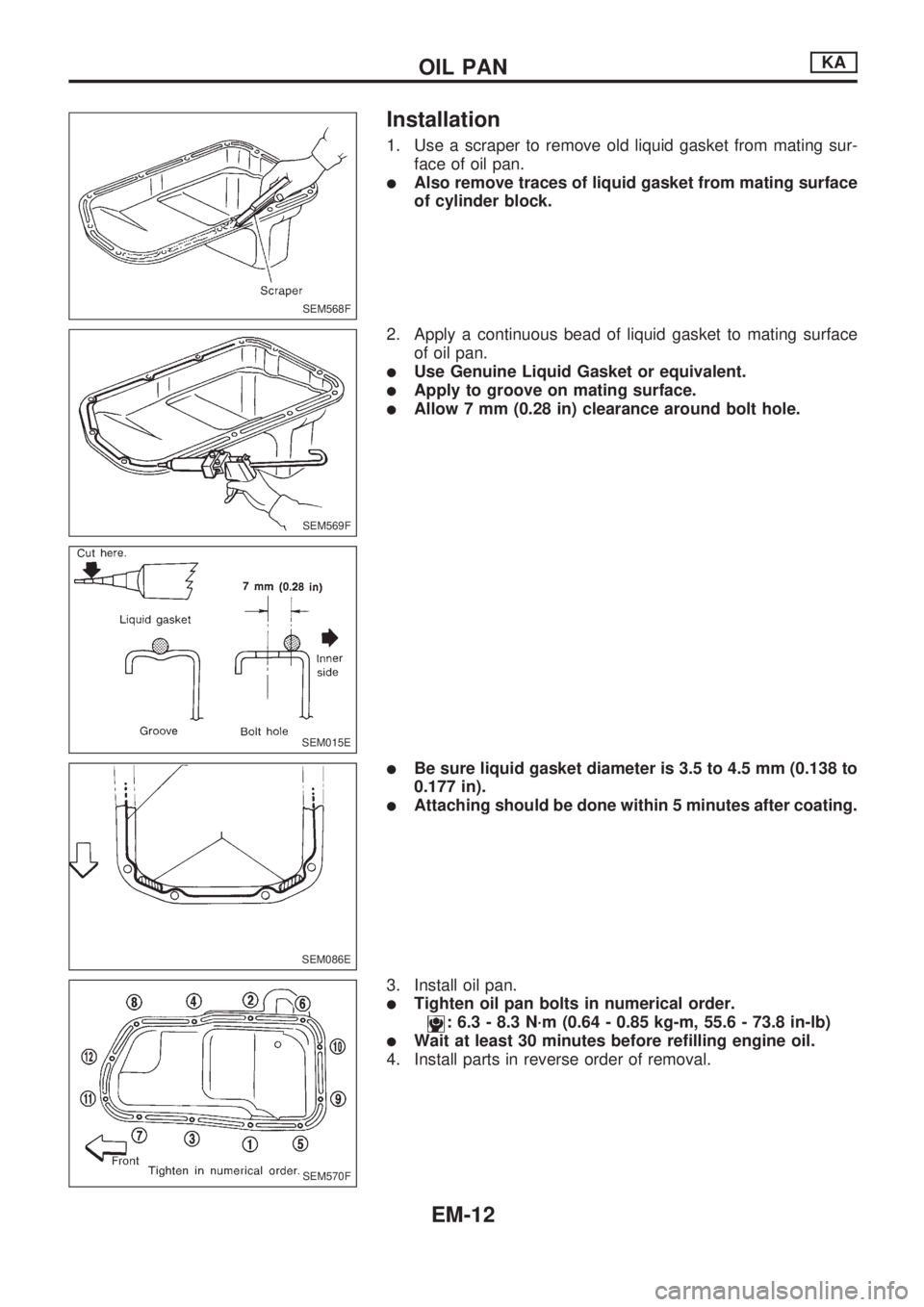
Installation
1. Use a scraper to remove old liquid gasket from mating sur-
face of oil pan.
lAlso remove traces of liquid gasket from mating surface
of cylinder block.
2. Apply a continuous bead of liquid gasket to mating surface
of oil pan.
lUse Genuine Liquid Gasket or equivalent.
lApply to groove on mating surface.
lAllow 7 mm (0.28 in) clearance around bolt hole.
lBe sure liquid gasket diameter is 3.5 to 4.5 mm (0.138 to
0.177 in).
lAttaching should be done within 5 minutes after coating.
3. Install oil pan.
lTighten oil pan bolts in numerical order.
: 6.3 - 8.3 N´m (0.64 - 0.85 kg-m, 55.6 - 73.8 in-lb)
lWait at least 30 minutes before refilling engine oil.
4. Install parts in reverse order of removal.
SEM568F
SEM569F
SEM015E
SEM086E
SEM570F
OIL PANKA
EM-12
Page 1566 of 1659
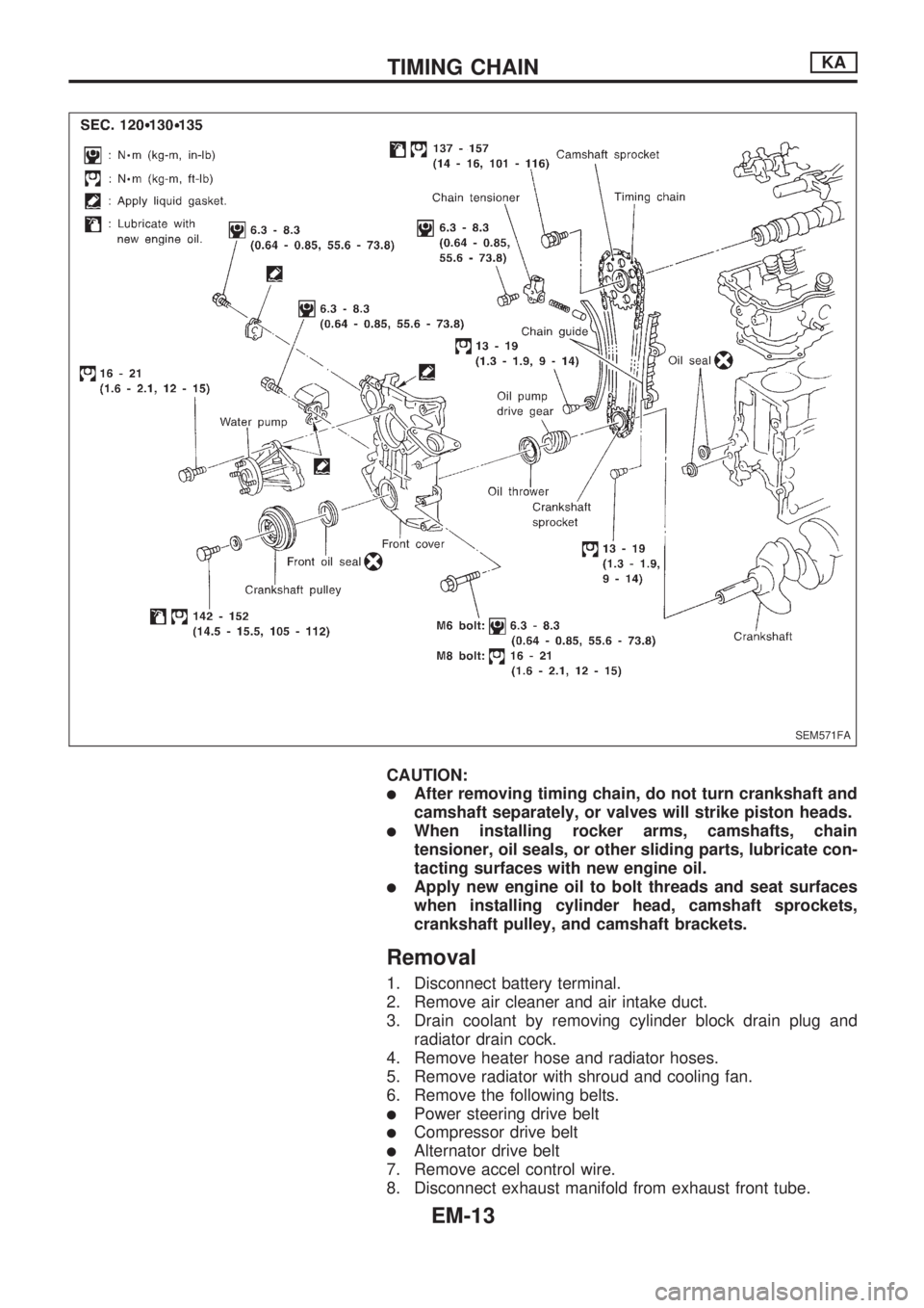
CAUTION:
lAfter removing timing chain, do not turn crankshaft and
camshaft separately, or valves will strike piston heads.
lWhen installing rocker arms, camshafts, chain
tensioner, oil seals, or other sliding parts, lubricate con-
tacting surfaces with new engine oil.
lApply new engine oil to bolt threads and seat surfaces
when installing cylinder head, camshaft sprockets,
crankshaft pulley, and camshaft brackets.
Removal
1. Disconnect battery terminal.
2. Remove air cleaner and air intake duct.
3. Drain coolant by removing cylinder block drain plug and
radiator drain cock.
4. Remove heater hose and radiator hoses.
5. Remove radiator with shroud and cooling fan.
6. Remove the following belts.
lPower steering drive belt
lCompressor drive belt
lAlternator drive belt
7. Remove accel control wire.
8. Disconnect exhaust manifold from exhaust front tube.
SEM571FA
TIMING CHAINKA
EM-13
Page 1567 of 1659
9. Remove PCV hoses from rocker cover.
10. Remove alternator and bracket.
11. Remove power steering oil pump and bracket from engine.
12. Remove vacuum hoses, fuel hoses, wires, harness, connec-
tors and so on.
13. Remove all high tension wires.
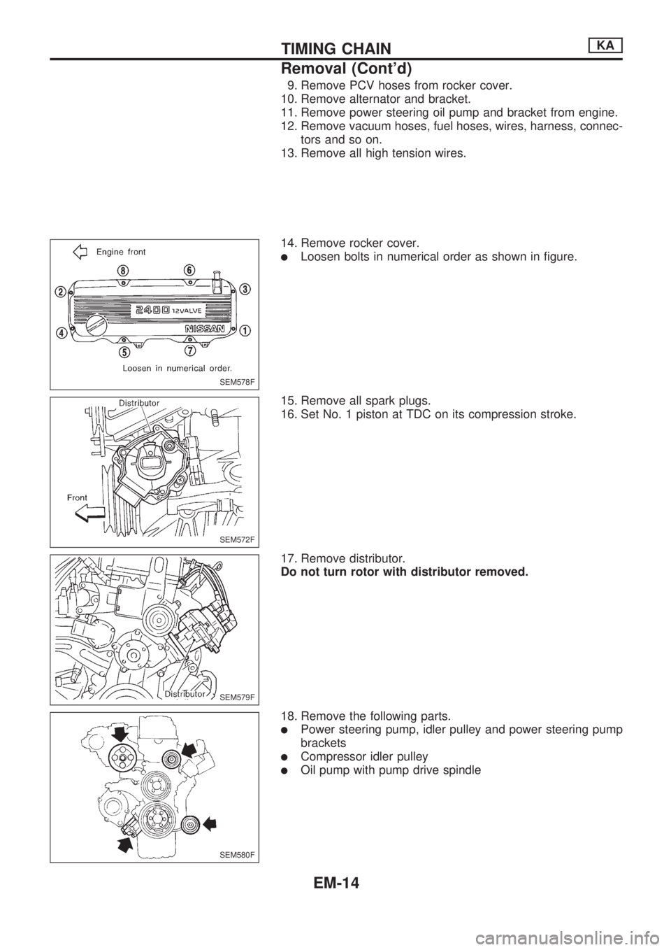
14. Remove rocker cover.
lLoosen bolts in numerical order as shown in figure.
15. Remove all spark plugs.
16. Set No. 1 piston at TDC on its compression stroke.
17. Remove distributor.
Do not turn rotor with distributor removed.
18. Remove the following parts.
lPower steering pump, idler pulley and power steering pump
brackets
lCompressor idler pulley
lOil pump with pump drive spindle
SEM578F
SEM572F
SEM579F
SEM580F
TIMING CHAINKA
Removal (Cont'd)
EM-14
Page 1568 of 1659
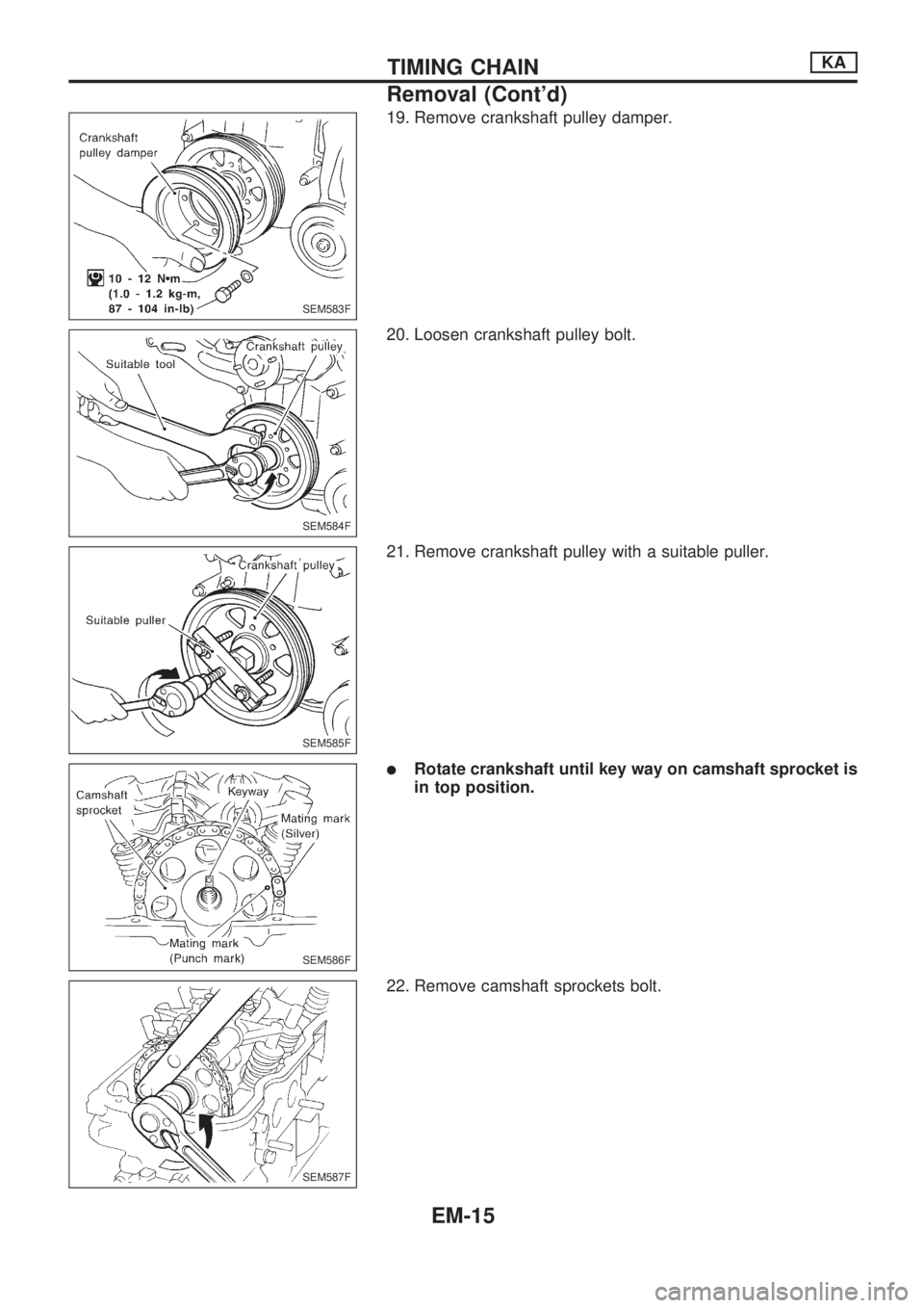
19. Remove crankshaft pulley damper.
20. Loosen crankshaft pulley bolt.
21. Remove crankshaft pulley with a suitable puller.
lRotate crankshaft until key way on camshaft sprocket is
in top position.
22. Remove camshaft sprockets bolt.
SEM583F
SEM584F
SEM585F
SEM586F
SEM587F
TIMING CHAINKA
Removal (Cont'd)
EM-15
Page 1569 of 1659
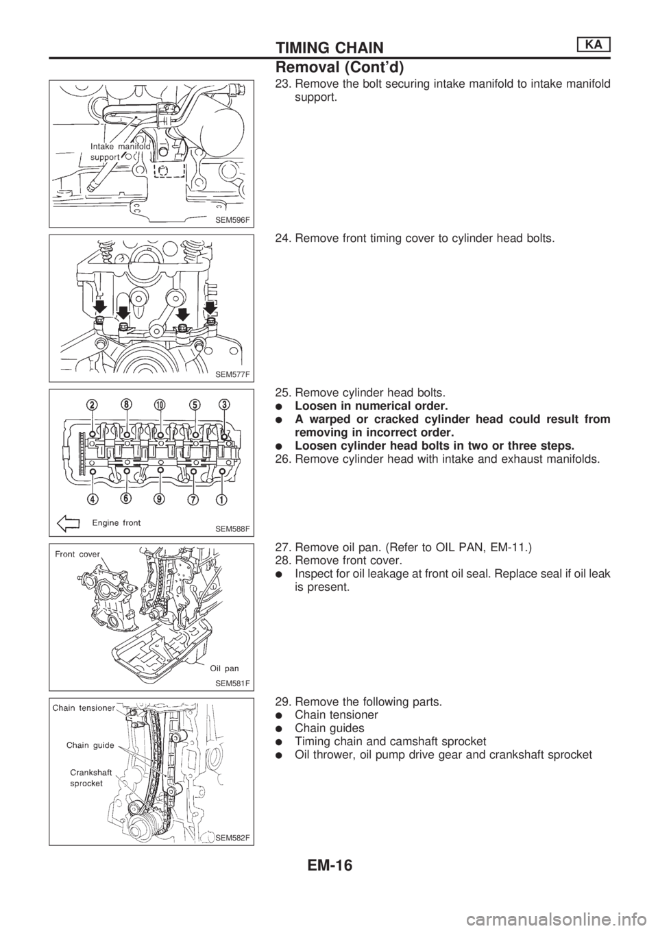
23. Remove the bolt securing intake manifold to intake manifold
support.
24. Remove front timing cover to cylinder head bolts.
25. Remove cylinder head bolts.
lLoosen in numerical order.
lA warped or cracked cylinder head could result from
removing in incorrect order.
lLoosen cylinder head bolts in two or three steps.
26. Remove cylinder head with intake and exhaust manifolds.
27. Remove oil pan. (Refer to OIL PAN, EM-11.)
28. Remove front cover.
lInspect for oil leakage at front oil seal. Replace seal if oil leak
is present.
29. Remove the following parts.
lChain tensioner
lChain guides
lTiming chain and camshaft sprocket
lOil thrower, oil pump drive gear and crankshaft sprocket
SEM596F
SEM577F
SEM588F
SEM581F
SEM582F
TIMING CHAINKA
Removal (Cont'd)
EM-16
Page 1570 of 1659
Inspection
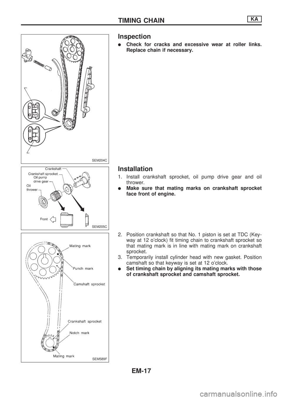
lCheck for cracks and excessive wear at roller links.
Replace chain if necessary.
Installation
1. Install crankshaft sprocket, oil pump drive gear and oil
thrower.
lMake sure that mating marks on crankshaft sprocket
face front of engine.
2. Position crankshaft so that No. 1 piston is set at TDC (Key-
way at 12 o'clock) fit timing chain to crankshaft sprocket so
that mating mark is in line with mating mark on crankshaft
sprocket.
3. Temporarily install cylinder head with new gasket. Position
camshaft so that keyway is set at 12 o'clock.
lSet timing chain by aligning its mating marks with those
of crankshaft sprocket and camshaft sprocket.
SEM204C
SEM205C
SEM589F
TIMING CHAINKA
EM-17
Trending: fuel cap release, fuse box location, horn wire, door lock, rear view mirror, fuel type, steering wheel adjustment
