NISSAN PRIMERA 1999 Electronic Repair Manual
PRIMERA 1999
NISSAN
NISSAN
https://www.carmanualsonline.info/img/5/57377/w960_57377-0.png
NISSAN PRIMERA 1999 Electronic Repair Manual
Trending: fuse box location, center console, timing belt, flat tire, water pump, fuse chart, wiring diagram
Page 1611 of 2267
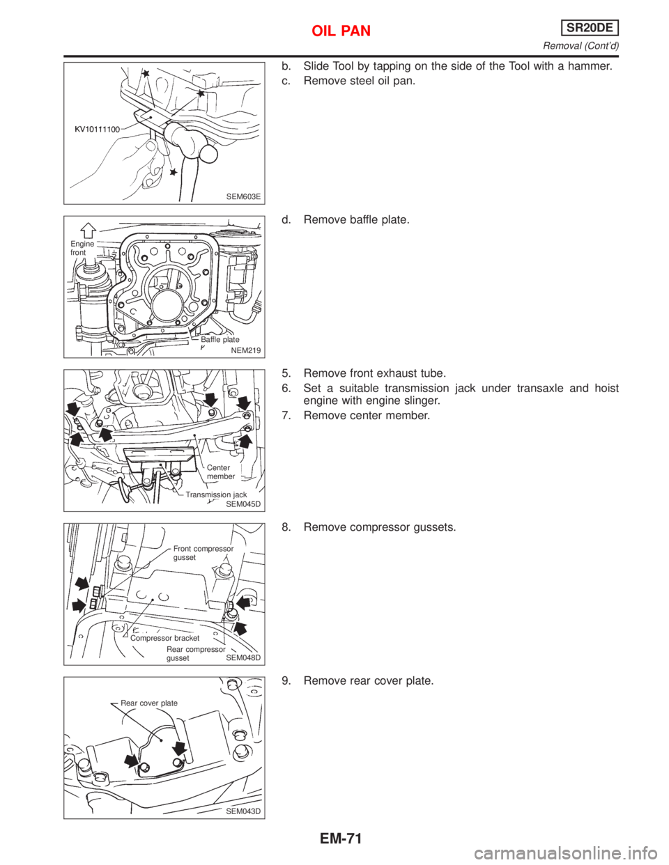
b. Slide Tool by tapping on the side of the Tool with a hammer.
c. Remove steel oil pan.
d. Remove baffle plate.
5. Remove front exhaust tube.
6. Set a suitable transmission jack under transaxle and hoist
engine with engine slinger.
7. Remove center member.
8. Remove compressor gussets.
9. Remove rear cover plate.
SEM603E
NEM219
.Engine
front
.Baffle plate
SEM045D Center
member
Transmission jack
.SEM048D Front compressor
gusset
Compressor bracket
Rear compressor
gusset
SEM043D Rear cover plate
OIL PANSR20DE
Removal (Cont'd)
EM-71
Page 1612 of 2267
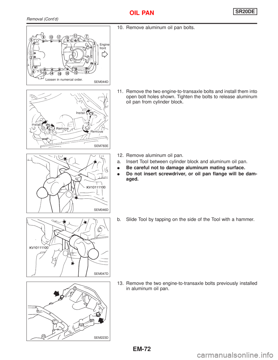
10. Remove aluminum oil pan bolts.
11. Remove the two engine-to-transaxle bolts and install them into
open bolt holes shown. Tighten the bolts to release aluminum
oil pan from cylinder block.
12. Remove aluminum oil pan.
a. Insert Tool between cylinder block and aluminum oil pan.
IBe careful not to damage aluminum mating surface.
IDo not insert screwdriver, or oil pan flange will be dam-
aged.
b. Slide Tool by tapping on the side of the Tool with a hammer.
13. Remove the two engine-to-transaxle bolts previously installed
in aluminum oil pan.
SEM044DEngine
front
Loosen in numercal order.
SEM783E
SEM046D
SEM047D
SEM223D
OIL PANSR20DE
Removal (Cont'd)
EM-72
Page 1613 of 2267
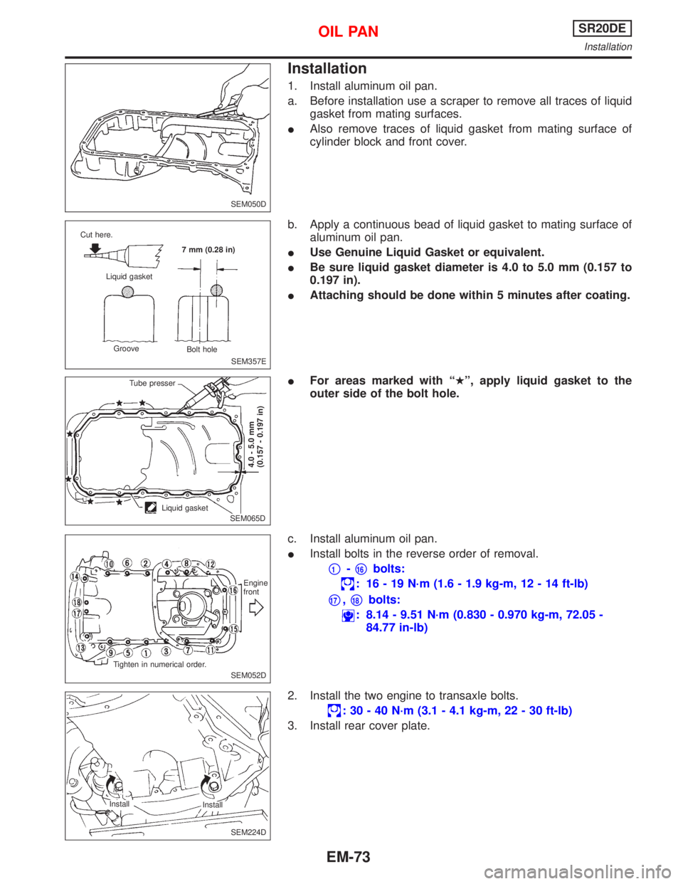
Installation
1. Install aluminum oil pan.
a. Before installation use a scraper to remove all traces of liquid
gasket from mating surfaces.
IAlso remove traces of liquid gasket from mating surface of
cylinder block and front cover.
b. Apply a continuous bead of liquid gasket to mating surface of
aluminum oil pan.
IUse Genuine Liquid Gasket or equivalent.
IBe sure liquid gasket diameter is 4.0 to 5.0 mm (0.157 to
0.197 in).
IAttaching should be done within 5 minutes after coating.
IFor areas marked with ªHº, apply liquid gasket to the
outer side of the bolt hole.
c. Install aluminum oil pan.
IInstall bolts in the reverse order of removal.
p1-p16bolts:
: 16 - 19 N´m (1.6 - 1.9 kg-m, 12 - 14 ft-lb)
p17,p18bolts:
: 8.14 - 9.51 N´m (0.830 - 0.970 kg-m, 72.05 -
84.77 in-lb)
2. Install the two engine to transaxle bolts.
: 30 - 40 N´m (3.1 - 4.1 kg-m, 22 - 30 ft-lb)
3. Install rear cover plate.
SEM050D
SEM357E Cut here.
Liquid gasket
Groove
Bolt hole 7 mm (0.28 in)
.SEM065D Tube presserLiquid gasket
4.0 - 5.0 mm
(0.157 - 0.197 in)
SEM052DEngine
front
Tighten in numerical order.
SEM224D Install
Install
OIL PANSR20DE
Installation
EM-73
Page 1614 of 2267
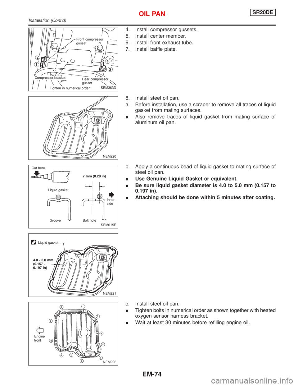
4. Install compressor gussets.
5. Install center member.
6. Install front exhaust tube.
7. Install baffle plate.
8. Install steel oil pan.
a. Before installation, use a scraper to remove all traces of liquid
gasket from mating surfaces.
IAlso remove traces of liquid gasket from mating surface of
aluminum oil pan.
b. Apply a continuous bead of liquid gasket to mating surface of
steel oil pan.
IUse Genuine Liquid Gasket or equivalent.
IBe sure liquid gasket diameter is 4.0 to 5.0 mm (0.157 to
0.197 in).
IAttaching should be done within 5 minutes after coating.
c. Install steel oil pan.
ITighten bolts in numerical order as shown together with heated
oxygen sensor harness bracket.
IWait at least 30 minutes before refilling engine oil.
SEM363D Front compressor
gusset
Compressor bracket
Rear compressor
gusset
Tighten in numerical order.
NEM220
SEM015E Cut here.
Liquid gasket7 mm (0.28 in)
Inner
side
Groove Bolt hole
NEM221
Liquid gasket
4.0 - 5.0 mm
(0.157 -
0.197 in)
NEM222p7
Engine
front
p3p1
p5
p9
p11
p2
p4p6
p10
p8
OIL PANSR20DE
Installation (Cont'd)
EM-74
Page 1615 of 2267
Components
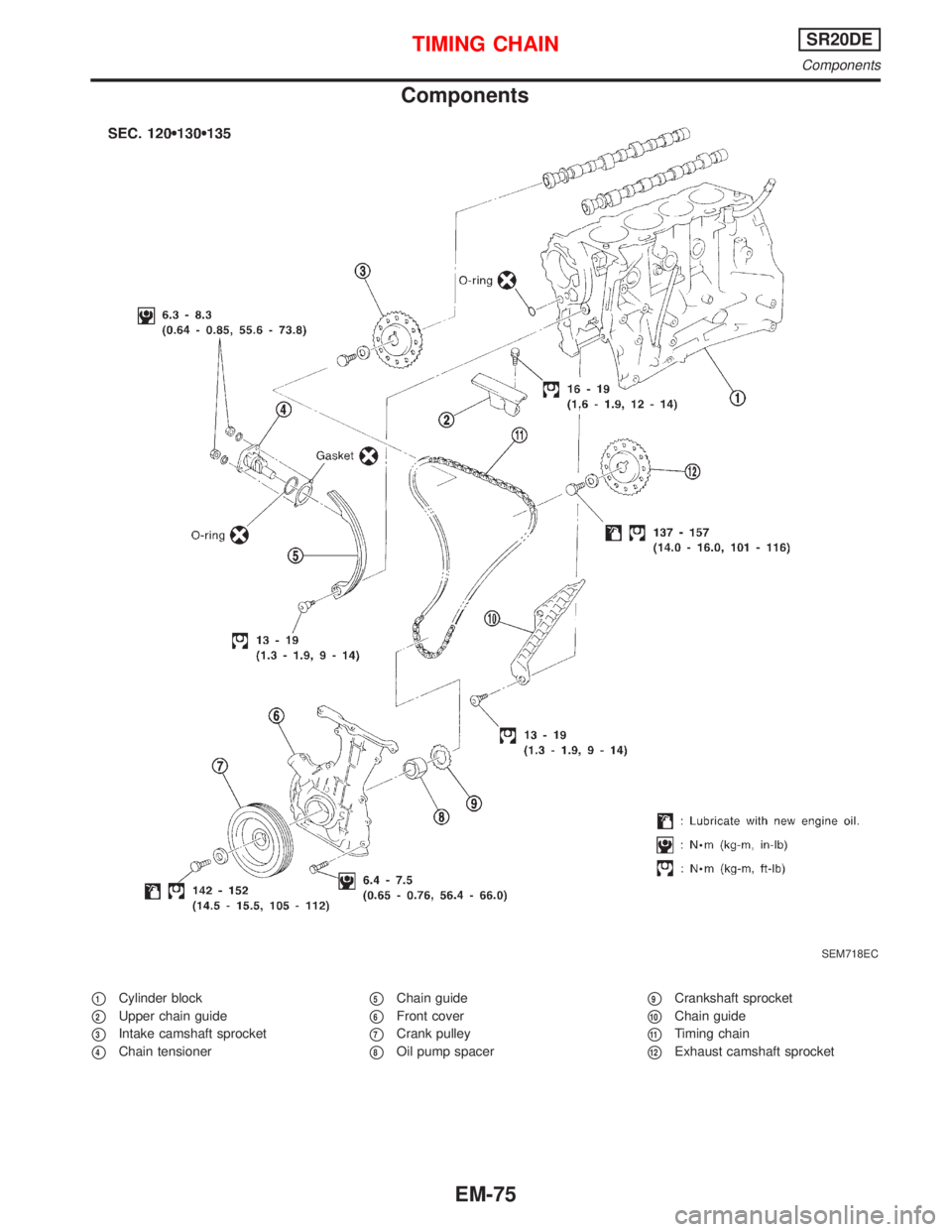
p1Cylinder block
p2Upper chain guide
p3Intake camshaft sprocket
p4Chain tensioner
p5Chain guide
p6Front cover
p7Crank pulley
p8Oil pump spacer
p9Crankshaft sprocket
p10Chain guide
p11Timing chain
p12Exhaust camshaft sprocket
SEM718EC
TIMING CHAINSR20DE
Components
EM-75
Page 1616 of 2267
CAUTION:
IAfter removing timing chain, do not turn crankshaft and
camshaft separately, or valves will strike piston heads.
IWhen installing chain tensioner, oil seals, or other sliding
parts, lubricate contacting surfaces with new engine oil.
IApply new engine oil to bolt threads and seat surfaces
when installing camshaft sprocket and crankshaft pulley.
RemovalNLEM01261. Remove engine under cover.
2. Remove front RH wheel and engine side cover.
3. Drain coolant by removing cylinder block drain plug and lower
radiator hose. Refer to MA-29, ªChanging Engine Coolantº.
4. Remove drive belts and water pump pulley.
5. Disconnect the following parts:
IVacuum hoses
IWires
IHarness
IConnectors
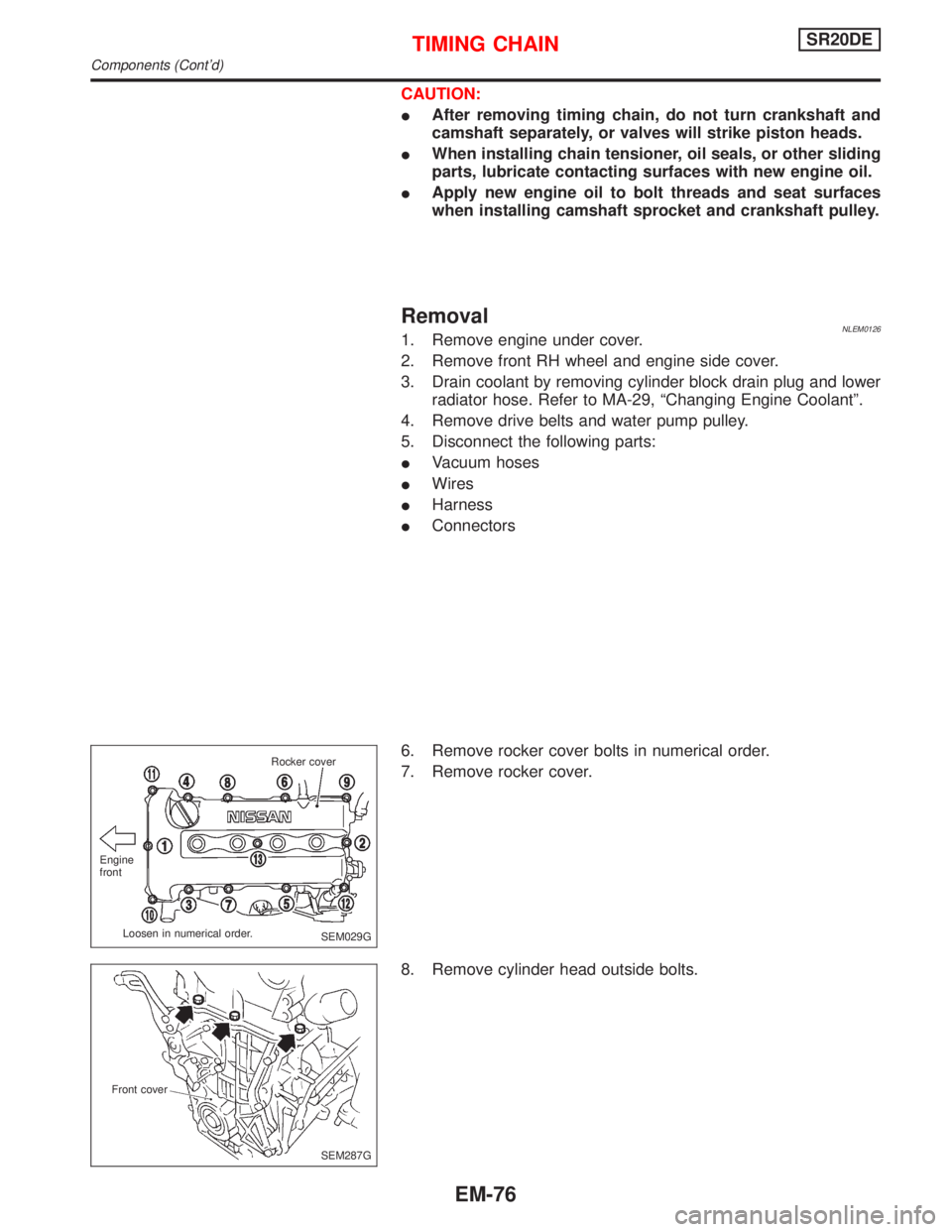
6. Remove rocker cover bolts in numerical order.
7. Remove rocker cover.
8. Remove cylinder head outside bolts.
SEM029G Engine
front
Loosen in numerical order.Rocker cover
SEM287G Front cover
TIMING CHAINSR20DE
Components (Cont'd)
EM-76
Page 1617 of 2267
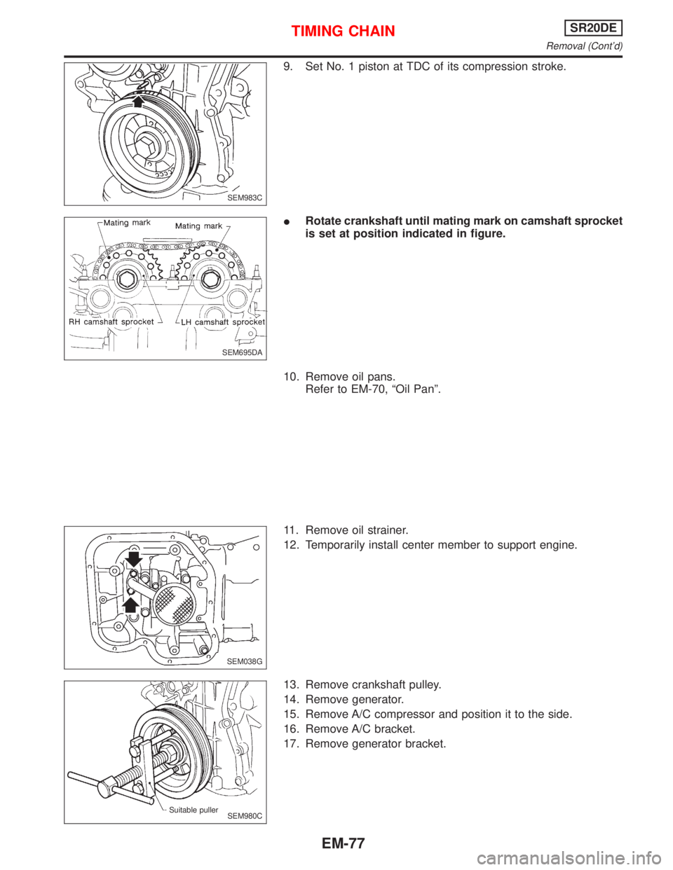
9. Set No. 1 piston at TDC of its compression stroke.
IRotate crankshaft until mating mark on camshaft sprocket
is set at position indicated in figure.
10. Remove oil pans.
Refer to EM-70, ªOil Panº.
11. Remove oil strainer.
12. Temporarily install center member to support engine.
13. Remove crankshaft pulley.
14. Remove generator.
15. Remove A/C compressor and position it to the side.
16. Remove A/C bracket.
17. Remove generator bracket.
SEM983C
SEM695DA
SEM038G
SEM980C Suitable puller
TIMING CHAINSR20DE
Removal (Cont'd)
EM-77
Page 1618 of 2267
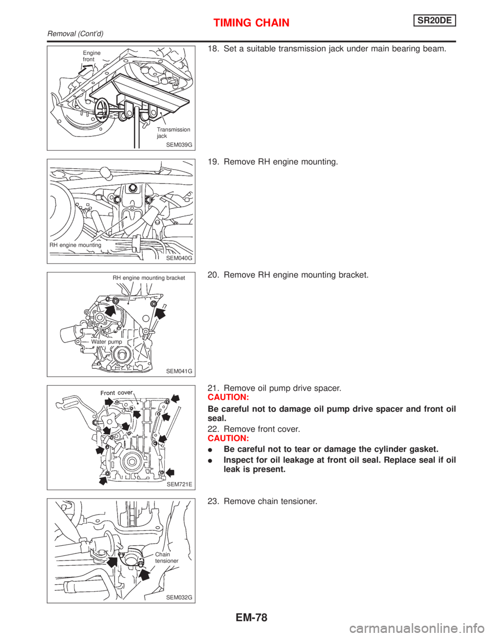
18. Set a suitable transmission jack under main bearing beam.
19. Remove RH engine mounting.
20. Remove RH engine mounting bracket.
21. Remove oil pump drive spacer.
CAUTION:
Be careful not to damage oil pump drive spacer and front oil
seal.
22. Remove front cover.
CAUTION:
IBe careful not to tear or damage the cylinder gasket.
IInspect for oil leakage at front oil seal. Replace seal if oil
leak is present.
23. Remove chain tensioner.
SEM039G Engine
front
Transmission
jack
SEM040G RH engine mounting
SEM041G RH engine mounting bracket
Water pump
SEM721E
.SEM032G Chain
tensioner
TIMING CHAINSR20DE
Removal (Cont'd)
EM-78
Page 1619 of 2267
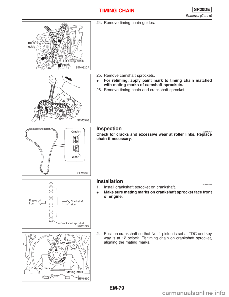
24. Remove timing chain guides.
25. Remove camshaft sprockets.
IFor retiming, apply paint mark to timing chain matched
with mating marks of camshaft sprockets.
26. Remove timing chain and crankshaft sprocket.
InspectionNLEM0127Check for cracks and excessive wear at roller links. Replace
chain if necessary.
InstallationNLEM01281. Install crankshaft sprocket on crankshaft.
IMake sure mating marks on crankshaft sprocket face front
of engine.
2. Position crankshaft so that No. 1 piston is set at TDC and key
way is at 12 oclock. Fit timing chain on crankshaft sprocket,
aligning the mating marks.
SEM982CA
SEM034G
SEM984C
SEM470E Engine
frontCrankshaft
side
Crankshaft sprocket
SEM985C
TIMING CHAINSR20DE
Removal (Cont'd)
EM-79
Page 1620 of 2267
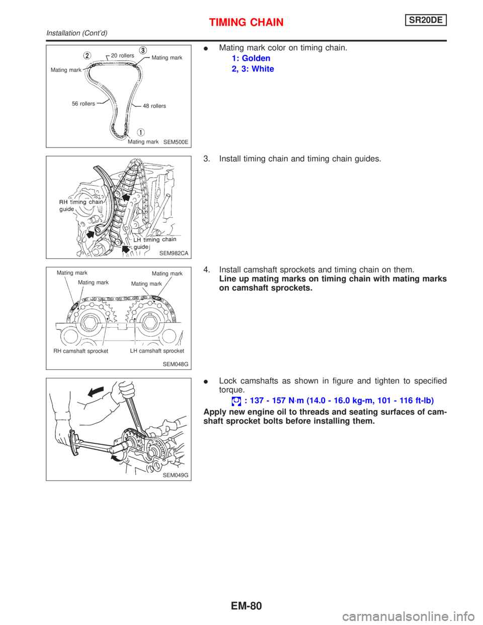
IMating mark color on timing chain.
1: Golden
2, 3: White
3. Install timing chain and timing chain guides.
4. Install camshaft sprockets and timing chain on them.
Line up mating marks on timing chain with mating marks
on camshaft sprockets.
ILock camshafts as shown in figure and tighten to specified
torque.
: 137 - 157 N×m (14.0 - 16.0 kg-m, 101 - 116 ft-lb)
Apply new engine oil to threads and seating surfaces of cam-
shaft sprocket bolts before installing them.
SEM500E 20 rollers
Mating mark
48 rollers
Mating mark 56 rollers Mating mark
SEM982CA
SEM048G Mating mark
Mating mark
.RH camshaft sprocket.LH camshaft sprocket Mating mark
Mating mark
SEM049G
TIMING CHAINSR20DE
Installation (Cont'd)
EM-80
Trending: tire pressure, auxiliary battery, open hood, transmission oil, jacking, load capacity, oil filter
