NISSAN PRIMERA 1999 Electronic Repair Manual
Manufacturer: NISSAN, Model Year: 1999, Model line: PRIMERA, Model: NISSAN PRIMERA 1999Pages: 2267, PDF Size: 35.74 MB
Page 291 of 2267
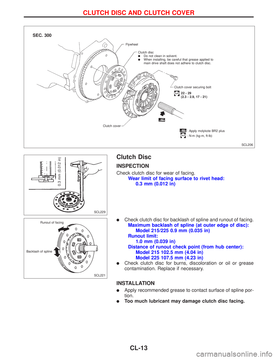
Clutch Disc
INSPECTION
Check clutch disc for wear of facing.
Wear limit of facing surface to rivet head:
0.3 mm (0.012 in)
lCheck clutch disc for backlash of spline and runout of facing.
Maximum backlash of spline (at outer edge of disc):
Model 215/225 0.9 mm (0.035 in)
Runout limit:
1.0 mm (0.039 in)
Distance of runout check point (from hub center):
Model 215 102.5 mm (4.04 in)
Model 225 107.5 mm (4.23 in)
lCheck clutch disc for burns, discoloration or oil or grease
contamination. Replace if necessary.
INSTALLATION
lApply recommended grease to contact surface of spline por-
tion.
lToo much lubricant may damage clutch disc facing.
SCL206 Flywheel
Clutch disc
lDo not clean in solvent.lWhen installing, be careful that grease applied to
main drive shaft does not adhere to clutch disc.
Clutch cover securing bolt
22-29
(2.3 - 2.9, 17 - 21)
: Apply molykote BR2 plus
: N´m (kg-m, ft-lb) Clutch cover
.
.
SEC. 300
SCL229
0.3 mm (0.012 in)
SCL221 Runout of facing
Backlash of spline
CLUTCH DISC AND CLUTCH COVER
CL-13
Page 292 of 2267
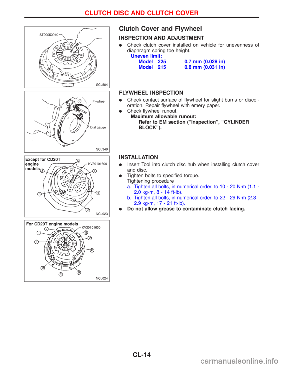
Clutch Cover and Flywheel
INSPECTION AND ADJUSTMENT
lCheck clutch cover installed on vehicle for unevenness of
diaphragm spring toe height.
Uneven limit:
Model 225 0.7 mm (0.028 in)
Model 215 0.8 mm (0.031 in)
FLYWHEEL INSPECTION
lCheck contact surface of flywheel for slight burns or discol-
oration. Repair flywheel with emery paper.
lCheck flywheel runout.
Maximum allowable runout:
Refer to EM section (ªInspectionº, ªCYLINDER
BLOCKº).
INSTALLATION
lInsert Tool into clutch disc hub when installing clutch cover
and disc.
lTighten bolts to specified torque.
Tightening procedure
a. Tighten all bolts, in numerical order, to 10 - 20 N´m (1.1 -
2.0 kg-m,8-14ft-lb).
b. Tighten all bolts, in numerical order, to 22 - 29 N´m (2.3 -
2.9 kg-m, 17 - 21 ft-lb).
lDo not allow grease to contaminate clutch facing.
SCL504
SCL349 Flywheel
Dial gauge
NCL023
Except for CD20T
engine
models6
1 KV30101600
4
2 53
NCL024 KV30101600
For CD20T engine models
1
2
3 45
6 7
8
9
CLUTCH DISC AND CLUTCH COVER
CL-14
Page 293 of 2267
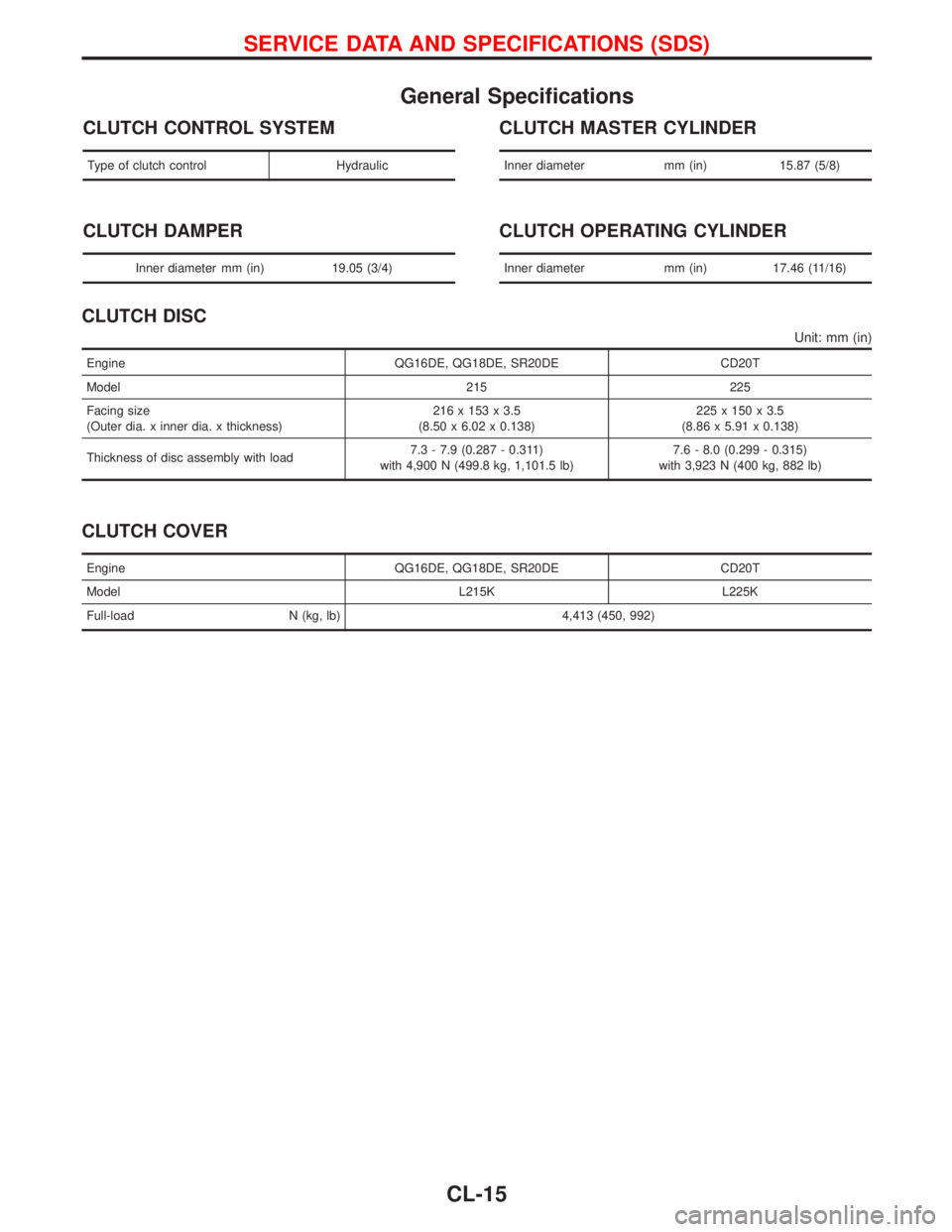
General Specifications
CLUTCH CONTROL SYSTEM
Type of clutch control Hydraulic
CLUTCH DAMPER
Inner diameter mm (in) 19.05 (3/4)
CLUTCH MASTER CYLINDER
Inner diameter mm (in) 15.87 (5/8)
CLUTCH OPERATING CYLINDER
Inner diameter mm (in) 17.46 (11/16)
CLUTCH DISC
Unit: mm (in)
Engine QG16DE, QG18DE, SR20DE CD20T
Model 215 225
Facing size
(Outer dia. x inner dia. x thickness)216 x 153 x 3.5
(8.50 x 6.02 x 0.138)225 x 150 x 3.5
(8.86 x 5.91 x 0.138)
Thickness of disc assembly with load7.3 - 7.9 (0.287 - 0.311)
with 4,900 N (499.8 kg, 1,101.5 lb)7.6 - 8.0 (0.299 - 0.315)
with 3,923 N (400 kg, 882 lb)
CLUTCH COVER
Engine QG16DE, QG18DE, SR20DE CD20T
Model L215K L225K
Full-load N (kg, lb) 4,413 (450, 992)
SERVICE DATA AND SPECIFICATIONS (SDS)
CL-15
Page 294 of 2267
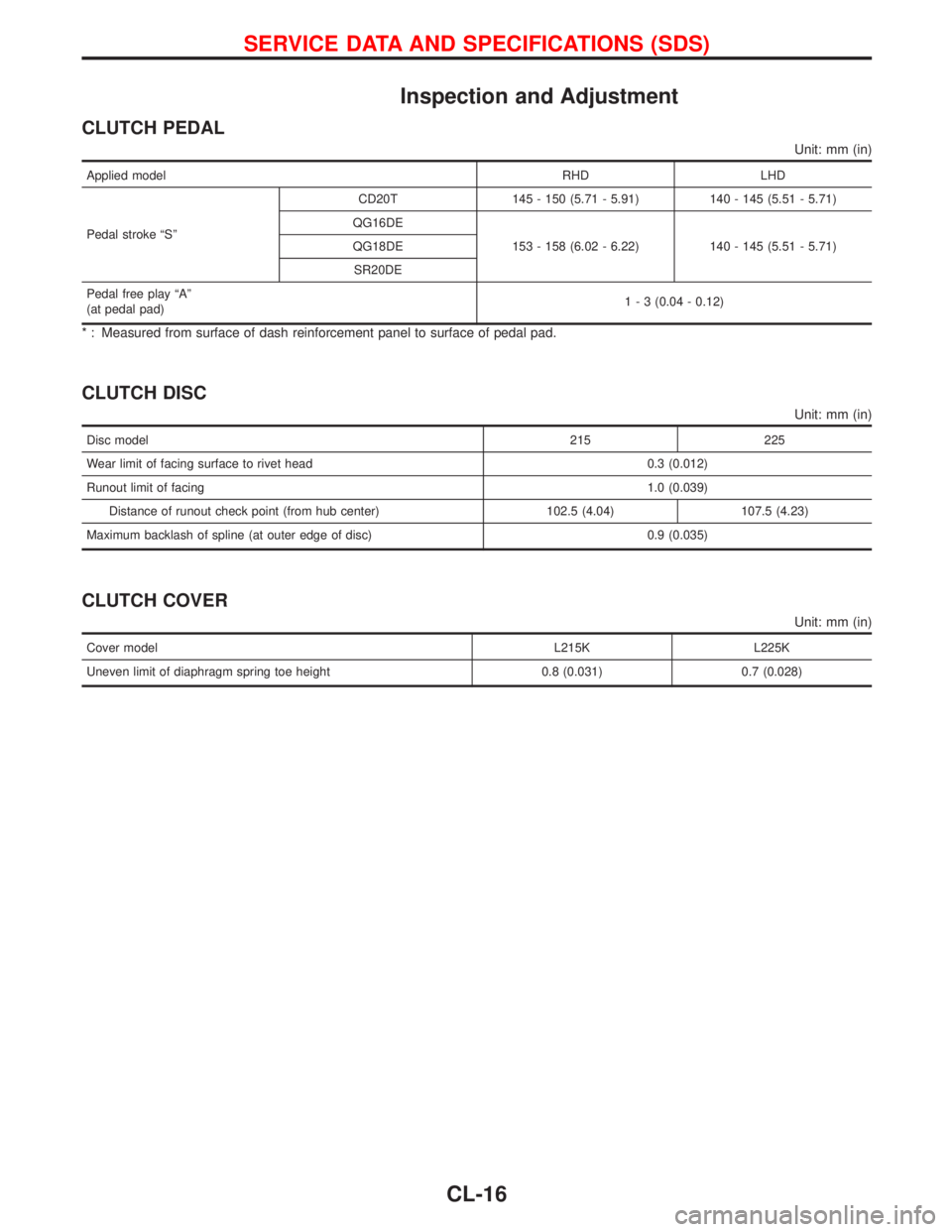
Inspection and Adjustment
CLUTCH PEDAL
Unit: mm (in)
Applied model RHD LHD
Pedal stroke ªSºCD20T 145 - 150 (5.71 - 5.91) 140 - 145 (5.51 - 5.71)
QG16DE
153 - 158 (6.02 - 6.22) 140 - 145 (5.51 - 5.71) QG18DE
SR20DE
Pedal free play ªAº
(at pedal pad)1 - 3 (0.04 - 0.12)
* : Measured from surface of dash reinforcement panel to surface of pedal pad.
CLUTCH DISC
Unit: mm (in)
Disc model215 225
Wear limit of facing surface to rivet head 0.3 (0.012)
Runout limit of facing1.0 (0.039)
Distance of runout check point (from hub center) 102.5 (4.04) 107.5 (4.23)
Maximum backlash of spline (at outer edge of disc) 0.9 (0.035)
CLUTCH COVER
Unit: mm (in)
Cover model L215K L225K
Uneven limit of diaphragm spring toe height 0.8 (0.031) 0.7 (0.028)
SERVICE DATA AND SPECIFICATIONS (SDS)
CL-16
Page 295 of 2267
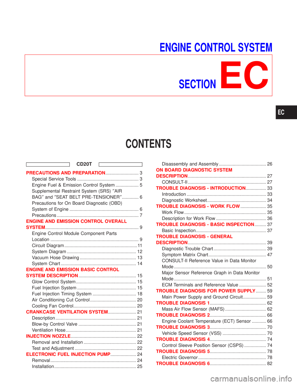
ENGINE CONTROL SYSTEM
SECTION
EC
CONTENTS
CD20T
PRECAUTIONS AND PREPARATION.......................... 3
Special Service Tools ................................................ 3
Engine Fuel & Emission Control System .................. 5
Supplemental Restraint System (SRS)²AIR
BAG²and²SEAT BELT PRE-TENSIONER²............. 6
Precautions for On Board Diagnostic (OBD)
System of Engine ...................................................... 6
Precautions ................................................................ 7
ENGINE AND EMISSION CONTROL OVERALL
SYSTEM......................................................................... 9
Engine Control Module Component Parts
Location ..................................................................... 9
Circuit Diagram ......................................................... 11
System Diagram ...................................................... 12
Vacuum Hose Drawing ............................................ 13
System Chart ........................................................... 14
ENGINE AND EMISSION BASIC CONTROL
SYSTEM DESCRIPTION............................................. 15
Glow Control System ............................................... 15
Fuel Injection System .............................................. 15
Fuel Injection Timing System .................................. 18
Air Conditioning Cut Control .................................... 20
Cooling Fan Control................................................. 20
CRANKCASE VENTILATION SYSTEM...................... 21
Description ............................................................... 21
Blow-by Control Valve ............................................. 21
Ventilation Hose ....................................................... 21
INJECTION NOZZLE................................................... 22
Removal and Installation ......................................... 22
Test and Adjustment ................................................ 22
ELECTRONIC FUEL INJECTION PUMP.................... 24
Removal ................................................................... 24
Installation ................................................................ 25Disassembly and Assembly ..................................... 26
ON BOARD DIAGNOSTIC SYSTEM
DESCRIPTION............................................................. 27
CONSULT-II ............................................................. 27
TROUBLE DIAGNOSIS - INTRODUCTION................ 33
Introduction .............................................................. 33
Diagnostic Worksheet .............................................. 34
TROUBLE DIAGNOSIS - WORK FLOW.................... 35
Work Flow ................................................................ 35
Description for Work Flow ....................................... 36
TROUBLE DIAGNOSIS - BASIC INSPECTION......... 37
Basic Inspection....................................................... 37
TROUBLE DIAGNOSIS - GENERAL
DESCRIPTION............................................................. 39
Diagnostic Trouble Chart ......................................... 39
Symptom Matrix Chart ............................................. 47
CONSULT-II Reference Value in Data Monitor
Mode ........................................................................ 50
Major Sensor Reference Graph in Data Monitor
Mode ........................................................................ 51
ECM Terminals and Reference Value ..................... 52
TROUBLE DIAGNOSIS FOR POWER SUPPLY........ 59
Main Power Supply and Ground Circuit .................. 59
TROUBLE DIAGNOSIS 1............................................ 62
Mass Air Flow Sensor (MAFS) ................................ 62
TROUBLE DIAGNOSIS 2............................................ 66
Engine Coolant Temperature (ECT) Sensor ........... 66
TROUBLE DIAGNOSIS 3............................................ 70
Vehicle Speed Sensor (VSS) .................................. 70
TROUBLE DIAGNOSIS 4............................................ 74
Control Sleeve Position Sensor (CSPS) ................. 74
TROUBLE DIAGNOSIS 5............................................ 78
Electric Governor ..................................................... 78
TROUBLE DIAGNOSIS 6............................................ 82
EC
Page 296 of 2267
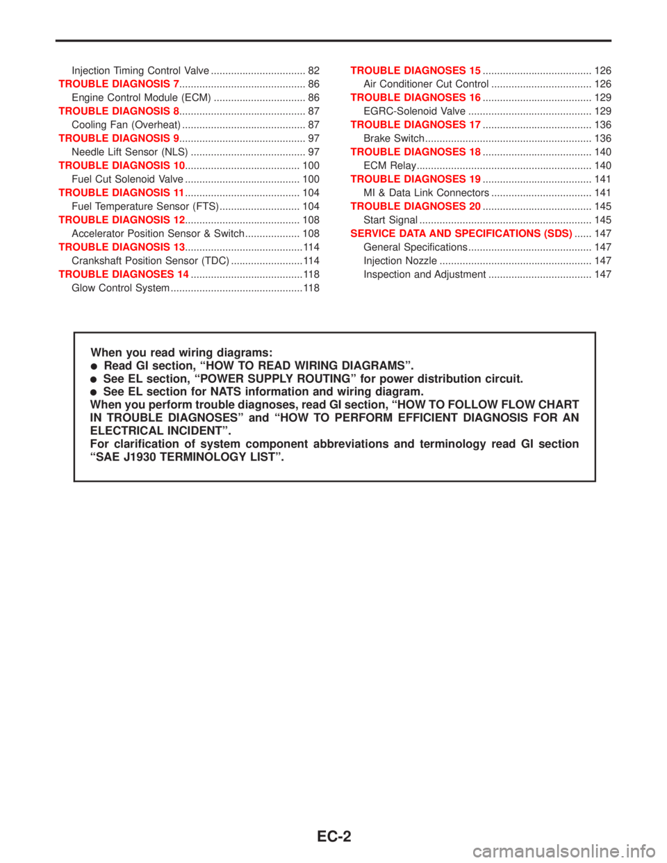
Injection Timing Control Valve ................................. 82
TROUBLE DIAGNOSIS 7............................................ 86
Engine Control Module (ECM) ................................ 86
TROUBLE DIAGNOSIS 8............................................ 87
Cooling Fan (Overheat) ........................................... 87
TROUBLE DIAGNOSIS 9............................................ 97
Needle Lift Sensor (NLS) ........................................ 97
TROUBLE DIAGNOSIS 10........................................ 100
Fuel Cut Solenoid Valve ........................................ 100
TROUBLE DIAGNOSIS 11........................................ 104
Fuel Temperature Sensor (FTS)............................ 104
TROUBLE DIAGNOSIS 12........................................ 108
Accelerator Position Sensor & Switch ................... 108
TROUBLE DIAGNOSIS 13......................................... 114
Crankshaft Position Sensor (TDC) ......................... 114
TROUBLE DIAGNOSES 14....................................... 118
Glow Control System .............................................. 118TROUBLE DIAGNOSES 15...................................... 126
Air Conditioner Cut Control ................................... 126
TROUBLE DIAGNOSES 16...................................... 129
EGRC-Solenoid Valve ........................................... 129
TROUBLE DIAGNOSES 17...................................... 136
Brake Switch .......................................................... 136
TROUBLE DIAGNOSES 18...................................... 140
ECM Relay............................................................. 140
TROUBLE DIAGNOSES 19...................................... 141
MI & Data Link Connectors ................................... 141
TROUBLE DIAGNOSES 20...................................... 145
Start Signal ............................................................ 145
SERVICE DATA AND SPECIFICATIONS (SDS)...... 147
General Specifications ........................................... 147
Injection Nozzle ..................................................... 147
Inspection and Adjustment .................................... 147
When you read wiring diagrams:
lRead GI section, ªHOW TO READ WIRING DIAGRAMSº.
lSee EL section, ªPOWER SUPPLY ROUTINGº for power distribution circuit.
lSee EL section for NATS information and wiring diagram.
When you perform trouble diagnoses, read GI section, ªHOW TO FOLLOW FLOW CHART
IN TROUBLE DIAGNOSESº and ªHOW TO PERFORM EFFICIENT DIAGNOSIS FOR AN
ELECTRICAL INCIDENTº.
For clarification of system component abbreviations and terminology read GI section
ªSAE J1930 TERMINOLOGY LISTº.
EC-2
Page 297 of 2267
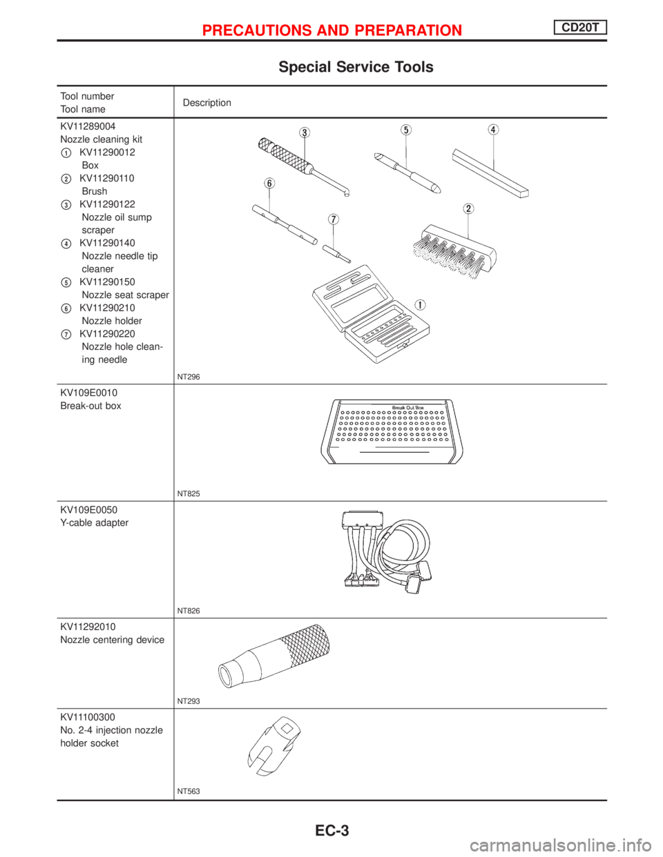
Special Service Tools
Tool number
Tool nameDescription
KV11289004
Nozzle cleaning kit
p1KV11290012
Box
p2KV11290110
Brush
p3KV11290122
Nozzle oil sump
scraper
p4KV11290140
Nozzle needle tip
cleaner
p5KV11290150
Nozzle seat scraper
p6KV11290210
Nozzle holder
p7KV11290220
Nozzle hole clean-
ing needle
NT296
KV109E0010
Break-out box
NT825
KV109E0050
Y-cable adapter
NT826
KV11292010
Nozzle centering device
NT293
KV11100300
No. 2-4 injection nozzle
holder socket
NT563
PRECAUTIONS AND PREPARATIONCD20T
EC-3
Page 298 of 2267
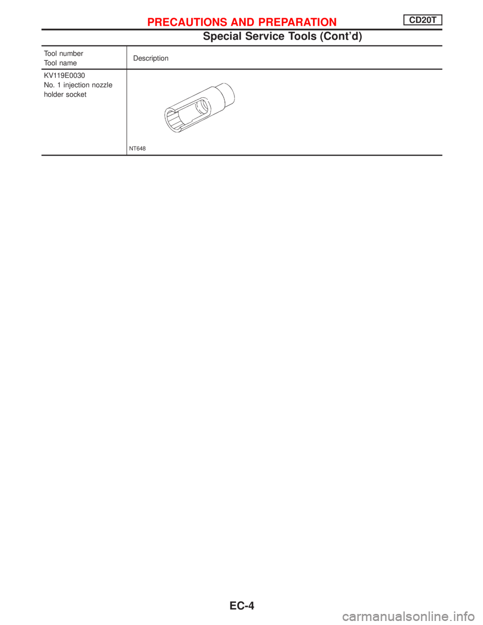
Tool number
Tool nameDescription
KV119E0030
No. 1 injection nozzle
holder socket
NT648
PRECAUTIONS AND PREPARATIONCD20T
Special Service Tools (Cont'd)
EC-4
Page 299 of 2267
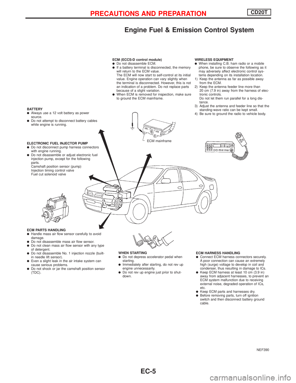
Engine Fuel & Emission Control System
NEF390 ECM (ECCS-D control module)
lDo not disassemble ECM.lIf a battery terminal is disconnected, the memory
will return to the ECM value.
The ECM will now start to self-control at its initial
value. Engine operation can vary slightly when
the terminal is disconnected. However, this is not
an indication of a problem. Do not replace parts
because of a slight variation.
lWhen ECM is removed for inspection, make sure
to ground the ECM mainframe.WIRELESS EQUIPMENT
lWhen installing C.B. ham radio or a mobile
phone, be sure to observe the following as it
may adversely affect electronic control sys-
tems depending on its installation location.
1) Keep the antenna as far as possible away
from the ECM.
2) Keep the antenna feeder line more than
20 cm (7.9 in) away from the harness of elec-
tronic controls.
Do not let them run parallel for a long dis-
tance.
3) Adjust the antenna and feeder line so that the
standing-wave ratio can be kept small.
4) Be sure to ground the radio to vehicle body.
ECM HARNESS HANDLING
lConnect ECM harness connectors securely.
A poor connection can cause an extremely
high (surge) voltage to develop in coil and
condenser, thus resulting in damage to ICs.
lKeep ECM harness at least 10 cm (3.9 in)
away from adjacent harnesses, to prevent an
ECM system malfunction due to receiving
external noise, degraded operation of ICs,
etc.
lKeep ECM parts and harnesses dry.lBefore removing parts, turn off ignition
switch and then disconnect battery ground
cable. WHEN STARTING
lDo not depress accelerator pedal when
starting.
lImmediately after starting, do not rev up
engine unnecessarily.
lDo not rev up engine just prior to shut-
down. ECM PARTS HANDLING
lHandle mass air flow sensor carefully to avoid
damage.
lDo not disassemble mass air flow sensor.lDo not clean mass air flow sensor with any type
of detergent.
lDo not disassemble No. 1 injection nozzle (built-
in needle lift sensor).
lEven a slight leak in the air intake system can
cause serious problems.
lDo not shock or jar the camshaft position sensor
(TDC). ELECTRONIC FUEL INJECTOR PUMP
lDo not disconnect pump harness connectors
with engine running.
lDo not disassemble or adjust electronic fuel
injection pump, except for the following
parts.
Camshaft position sensor (pump)
Injection timing control valve
Fuel cut solenoid valve BATTERY
lAlways use a 12 volt battery as power
source.
lDo not attempt to disconnect battery cables
while engine is running.
ECM mainframe
PRECAUTIONS AND PREPARATIONCD20T
EC-5
Page 300 of 2267
Supplemental Restraint System (SRS) ªAIR
BAGº and ªSEAT BELT PRE-TENSIONERº
NCEC0002
The Supplemental Restraint System ªAIR BAGº and ªSEAT BELT PRE-TENSIONERº, used along with a seat
belt, help to reduce the risk or severity of injury to the driver and front passenger in a frontal collision. The
Supplemental Restraint System consists of air bag modules (located in the center of the steering wheel and
on the instrument panel on the passenger side), seat belt pre-tensioners, a diagnosis sensor unit, warning
lamp, wiring harness and spiral cable.
In addition to the supplemental air bag modules for a frontal collision, the supplemental side air bag used
along with the seat belt helps to reduce the risk or severity of injury to the driver and front passenger in a
side collision. The supplemental side air bag consists of air bag modules (located in the outer side of front
seats), satellite sensor, diagnosis sensor unit (one of components of supplemental air bags for a frontal
collision), wiring harness, warning lamp (one of components of supplemental air bags for a frontal collision).
Information necessary to service the system safely is included in theRS sectionof this Service Manual.
WARNING:
lTo avoid rendering the SRS inoperative, which could increase the risk of personal injury or death
in the event of a collision which would result in air bag inflation, all maintenance must be per-
formed by an authorized NISSAN dealer.
lImproper maintenance, including incorrect removal and installation of the SRS, can lead to per-
sonal injury caused by unintentional activation of the system.
lDo not use electrical test equipment on any circuit related to the SRS unless instructed to in this
Service Manual. SRS wiring harnesses (except ªSEAT BELT PRE-TENSIONERº connector) can be
identified with yellow harness connector (and with yellow harness protector or yellow insulation
tape before the harness connectors).
Precautions for On Board Diagnostic (OBD)
System of Engine
NCEC0003
The ECM has an on board diagnostic system. It will light up the malfunction indicator (MI) to warn the driver
of a malfunction causing emission deterioration.
CAUTION:
lBe sure to turn the ignition switch ªOFFº and disconnect the negative battery terminal before any
repair or inspection work. The open/short circuit of related switches, sensors, solenoid valves,
etc. will cause the MI to light up.
lBe sure to connect and lock the connectors securely after work. A loose (unlocked) connector
will cause the MI to light up due to the open circuit. (Be sure the connector is free from water,
grease, dirt, bent terminals, etc.)
lCertain systems and components, especially those related to OBD, may use a new style slide-
locking type harness connector.
For description and how to disconnect, refer to EL section, ªDescriptionº, ªHARNESS CONNEC-
TORº.
lBe sure to route and secure the harnesses properly after work. The interference of the harness
with a bracket, etc. may cause the MI to light up due to the short circuit.
lBe sure to connect rubber tubes properly after work. A misconnected or disconnected rubber
tube may cause the MI to light up due to the malfunction of the EGR system or fuel injection
system, etc.
lBe sure to erase the unnecessary malfunction information (repairs completed) from the ECM
before returning the vehicle to the customer.
PRECAUTIONS AND PREPARATIONCD20T
EC-6