NISSAN PRIMERA 1999 Electronic Repair Manual
PRIMERA 1999
NISSAN
NISSAN
https://www.carmanualsonline.info/img/5/57377/w960_57377-0.png
NISSAN PRIMERA 1999 Electronic Repair Manual
Trending: towing, wheel size, door lock, headlights, tire pressure, trailer, mirror
Page 251 of 2267
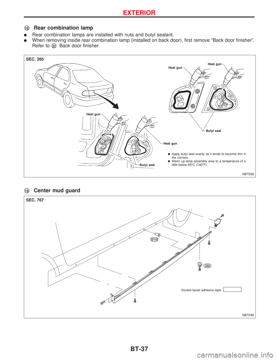
p18Rear combination lamp
lRear combination lamps are installed with nuts and butyl sealant.
lWhen removing inside rear combination lamp (installed on back door), first remove ªBack door finisherº.
Refer to
p22Back door finisher.
p19Center mud guard
NBT056 Heat gun
Heat gun
Butyl seal Heat gun
SEC. 265
Heat gun
Butyl seal
lApply butyl seal evenly as it tends to become thin in
the corners.
lWarm up lamp assembly area to a temperature of a
little below 60ÉC (140ÉF).
NBT046
SEC. 767
Double-faced adhesive tape
CF118
C205
EXTERIOR
BT-37
Page 252 of 2267
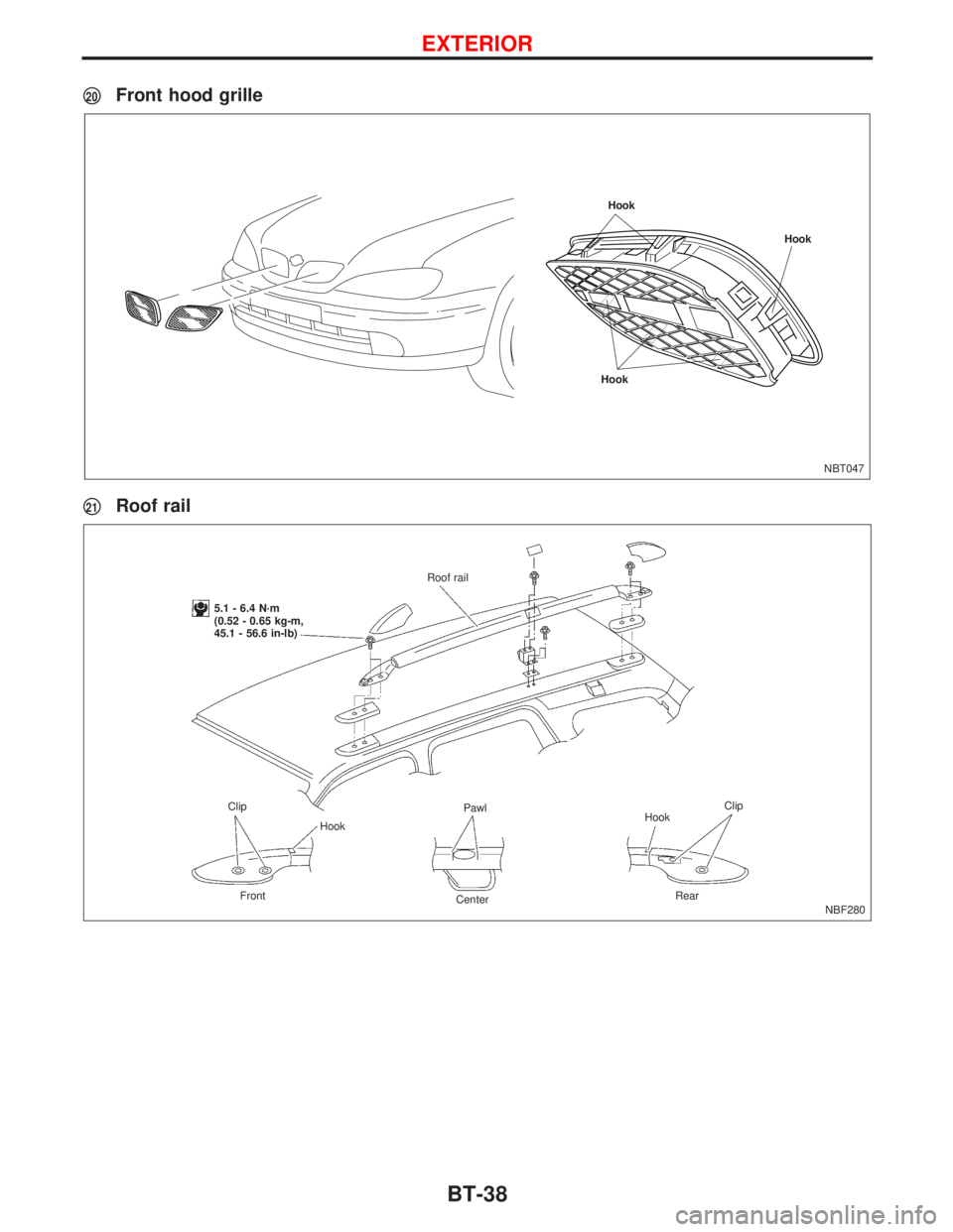
p20Front hood grille
p21Roof rail
NBT047
Hook
HookHook
NBF280 Roof rail
5.1 - 6.4 N´m
(0.52 - 0.65 kg-m,
45.1 - 56.6 in-lb)
Clip
Clip
HookPawl
Hook
Front
CenterRear
EXTERIOR
BT-38
Page 253 of 2267
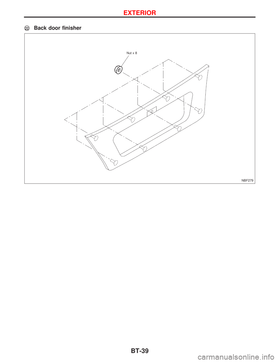
p22Back door finisher
NBF279 Nutx8
EXTERIOR
BT-39
Page 254 of 2267
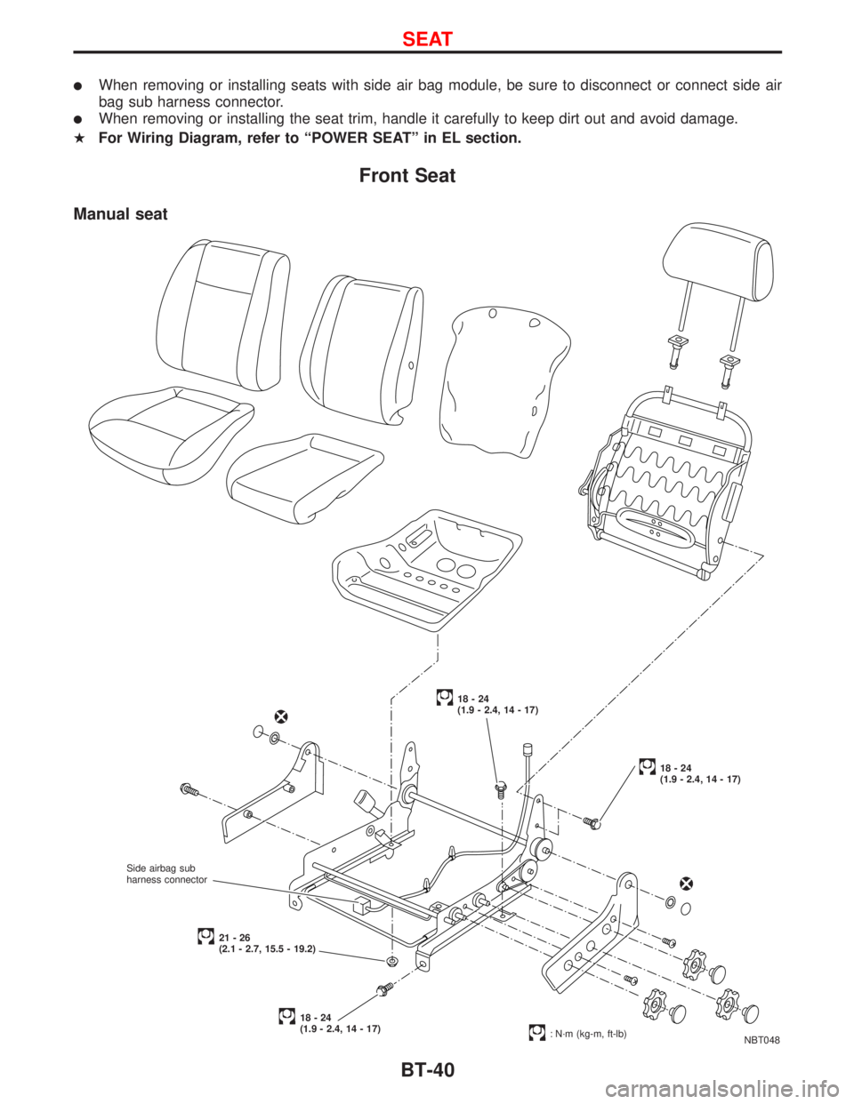
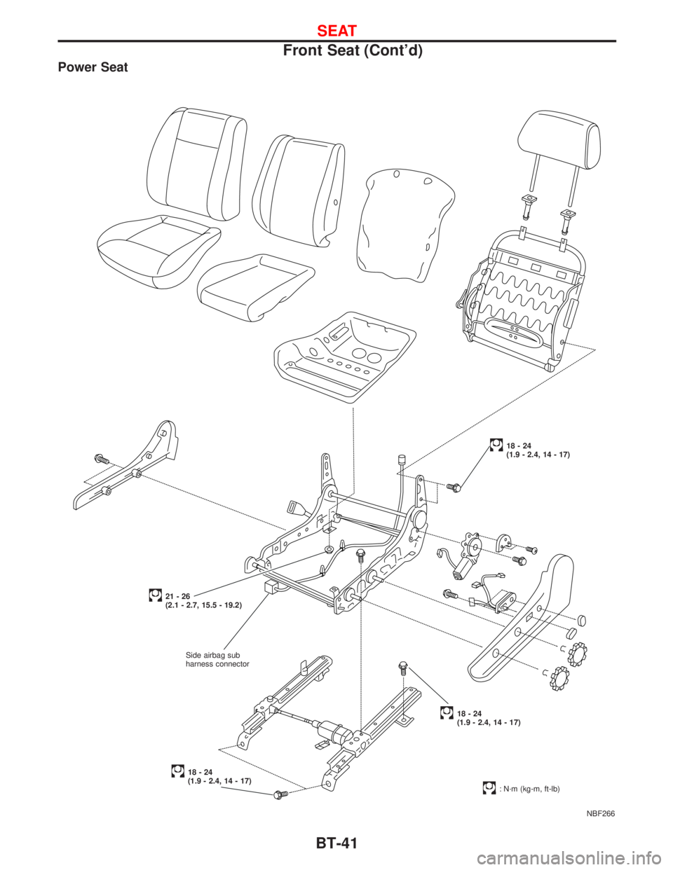
lWhen removing or installing seats with side air bag module, be sure to disconnect or connect side air
bag sub harness connector.
lWhen removing or installing the seat trim, handle it carefully to keep dirt out and avoid damage.
HFor Wiring Diagram, refer to ªPOWER SEATº in EL section.
Front Seat
NBT048
18-24
(1.9 - 2.4, 14 - 17)
18-24
(1.9 - 2.4, 14 - 17)
18-24
(1.9 - 2.4, 14 - 17)
: N´m (kg-m, ft-lb)
21-26
(2.1 - 2.7, 15.5 - 19.2)
Manual seat
Side airbag sub
harness connector
SEAT
BT-40
Page 255 of 2267
Power Seat
NBF266
18-24
(1.9 - 2.4, 14 - 17)
18-24
(1.9 - 2.4, 14 - 17)
18-24
(1.9 - 2.4, 14 - 17)
: N´m (kg-m, ft-lb)
21-26
(2.1 - 2.7, 15.5 - 19.2)
Side airbag sub
harness connector
SEAT
Front Seat (Cont'd)
BT-41
Page 256 of 2267
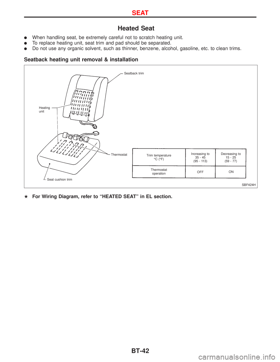
Heated Seat
lWhen handling seat, be extremely careful not to scratch heating unit.
lTo replace heating unit, seat trim and pad should be separated.
lDo not use any organic solvent, such as thinner, benzene, alcohol, gasoline, etc. to clean trims.
Seatback heating unit removal & installation
HFor Wiring Diagram, refer to ªHEATED SEATº in EL section.
SBF424H Seatback trim
Heating
unit
Thermostat
Seat cushion trimTrim temperature
ÉC (ÉF)
Thermostat
operationIncreasing to
35-45
(95 - 113)
OFFDecreasing to
15-25
(59 - 77)
ON
SEAT
BT-42
Page 257 of 2267
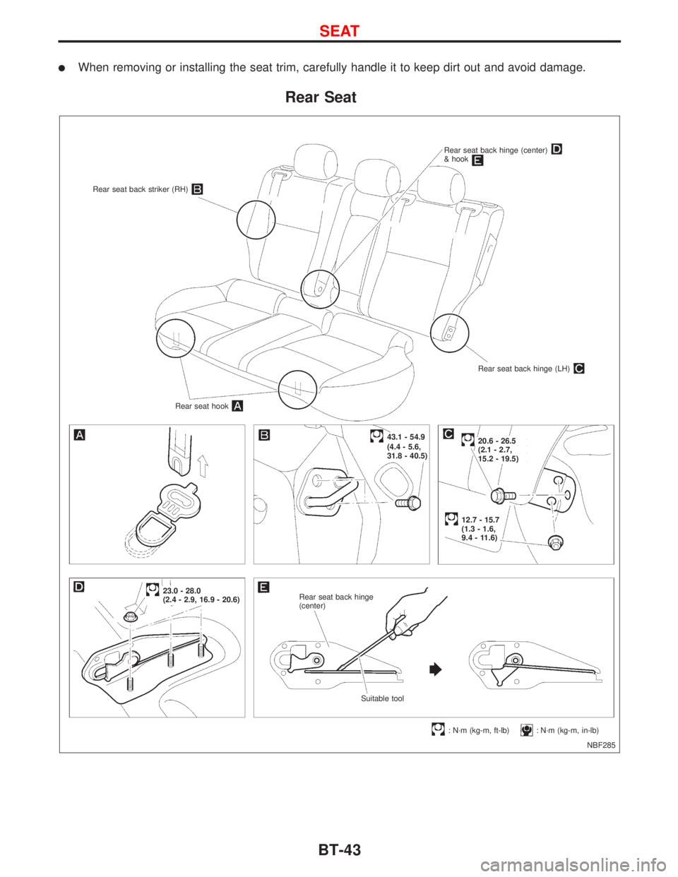
lWhen removing or installing the seat trim, carefully handle it to keep dirt out and avoid damage.
Rear Seat
NBF285 Rear seat back striker (RH)
Rear seat back hinge (center)& hook
Rear seat back hinge (LH)
Rear seat hook
Rear seat back hinge
(center)
12.7 - 15.7
(1.3 - 1.6,
9.4 - 11.6)
.23.0 - 28.0
(2.4 - 2.9, 16.9 - 20.6)
.43.1 - 54.9
(4.4 - 5.6,
31.8 - 40.5)
: N´m (kg-m, ft-lb): N´m (kg-m, in-lb) Suitable tool
20.6 - 26.5
(2.1 - 2.7,
15.2 - 19.5)
SEAT
BT-43
Page 258 of 2267
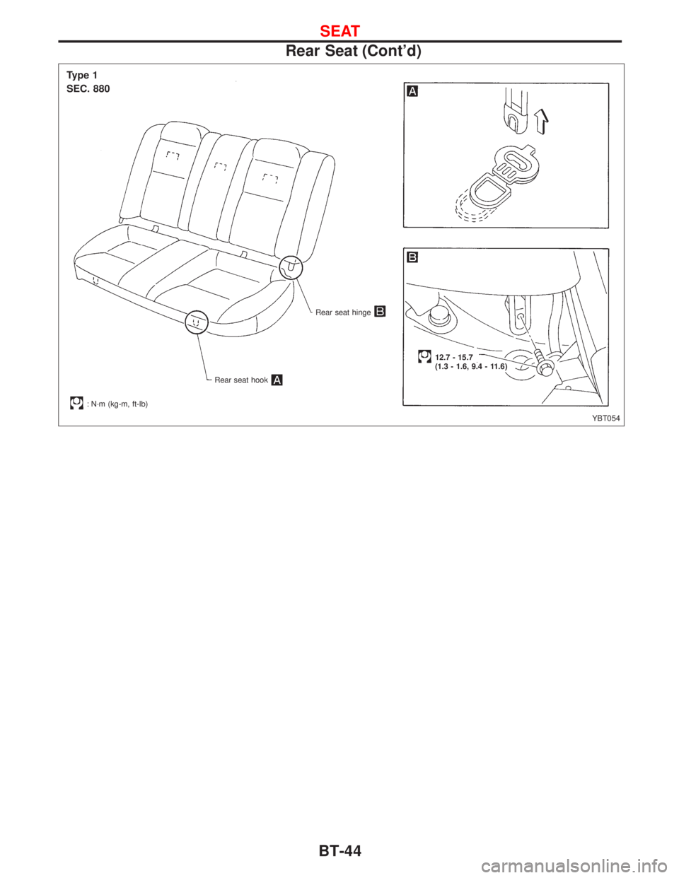
YBT054
Type 1
SEC. 880
Rear seat hinge
Rear seat hook
: N´m (kg-m, ft-lb)
12.7 - 15.7
(1.3 - 1.6, 9.4 - 11.6)
SEAT
Rear Seat (Cont'd)
BT-44
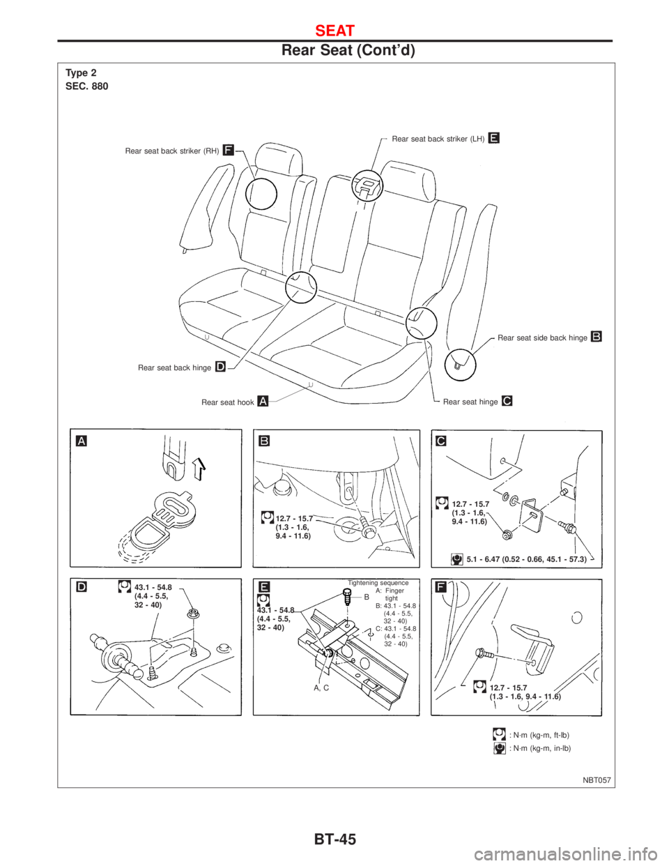
Page 259 of 2267
NBT057
Type 2
SEC. 880
Rear seat back striker (RH)
Rear seat back striker (LH)
Rear seat side back hinge
Rear seat hingeRear seat hook
Rear seat back hinge
12.7 - 15.7
(1.3 - 1.6,
9.4 - 11.6)
12.7 - 15.7
(1.3 - 1.6, 9.4 - 11.6)
12.7 - 15.7
(1.3 - 1.6,
9.4 - 11.6)
43.1 - 54.8
(4.4 - 5.5,
32 - 40)
43.1 - 54.8
(4.4 - 5.5,
32 - 40)
: N´m (kg-m, ft-lb)
: N´m (kg-m, in-lb)
Tightening sequence
A: Finger
tight
B: 43.1 - 54.8
(4.4 - 5.5,
32 - 40)
C: 43.1 - 54.8
(4.4 - 5.5,
32 - 40)
A, CB
5.1 - 6.47 (0.52 - 0.66, 45.1 - 57.3)
.
SEAT
Rear Seat (Cont'd)
BT-45
Page 260 of 2267
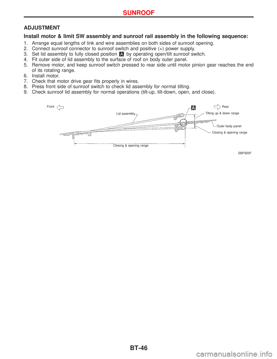
ADJUSTMENT
Install motor & limit SW assembly and sunroof rail assembly in the following sequence:
1. Arrange equal lengths of link and wire assemblies on both sides of sunroof opening.
2. Connect sunroof connector to sunroof switch and positive (+) power supply.
3. Set lid assembly to fully closed position
by operating open/tilt sunroof switch.
4. Fit outer side of lid assembly to the surface of roof on body outer panel.
5. Remove motor, and keep sunroof switch pressed to rear side until motor pinion gear reaches the end
of its rotating range.
6. Install motor.
7. Check that motor drive gear fits properly in wires.
8. Press front side of sunroof switch to check lid assembly for normal tilting.
9. Check sunroof lid assembly for normal operations (tilt-up, tilt-down, open, and close).
SBF920F Front
Lid assembly
Closing & opening rangeRear
Tilting up & down range
Outer body panel
Closing & opening range
SUNROOF
BT-46
Trending: sr20de, belt, airbag, dimensions, automatic transmission, spare tire, key battery
