NISSAN PRIMERA 1999 Electronic Repair Manual
PRIMERA 1999
NISSAN
NISSAN
https://www.carmanualsonline.info/img/5/57377/w960_57377-0.png
NISSAN PRIMERA 1999 Electronic Repair Manual
Trending: trunk, fog light bulb, spare tire, ESP, wiper blades, steering wheel adjustment, jump start
Page 271 of 2267
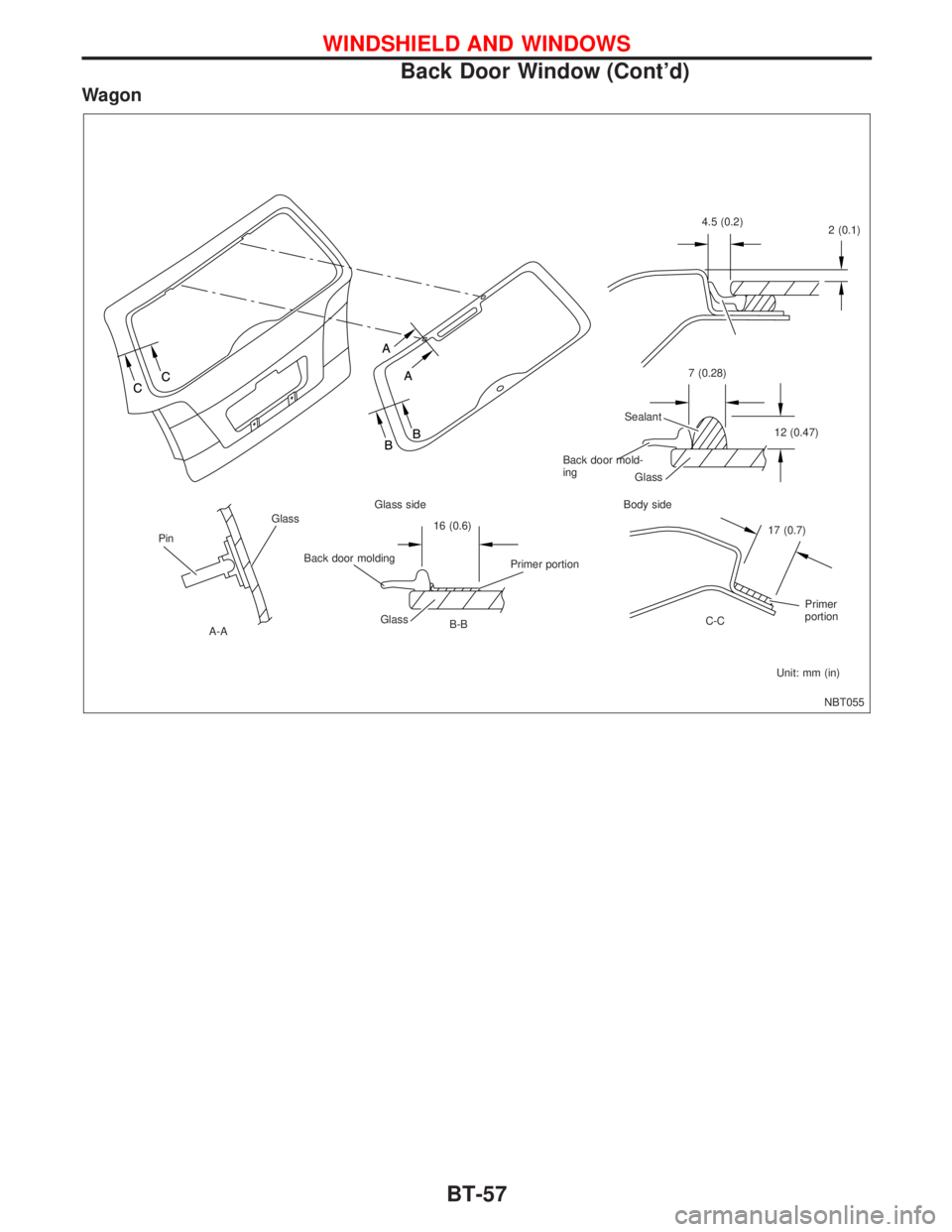
Wagon
NBT055
Glass
Pin
.A-AGlass side
16 (0.6)
Primer portion
Glass
B-BBody side
17 (0.7)
Primer
portion
C-C
Unit: mm (in) Glass Sealant7 (0.28)
12 (0.47) 4.5 (0.2)
2 (0.1)
Back door moldingBack door mold-
ing
WINDSHIELD AND WINDOWS
Back Door Window (Cont'd)
BT-57
Page 272 of 2267
Door Mirror
CAUTION:
Be careful not to scratch door rearview mirror body.
HFor Wiring Diagram, refer to ªPOWER DOOR MIRRORº in EL section.
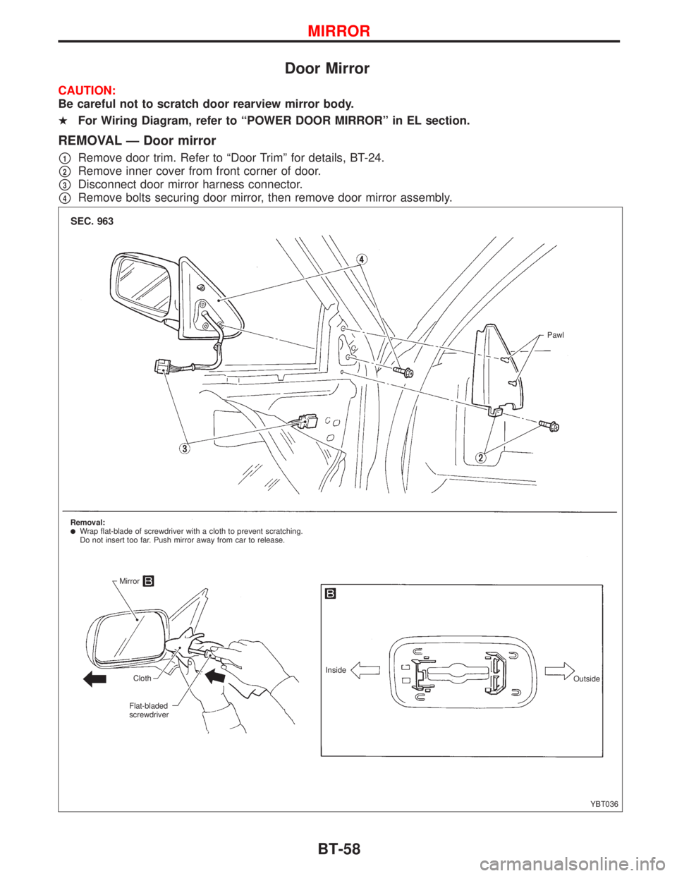
REMOVAL Ð Door mirror
p1Remove door trim. Refer to ªDoor Trimº for details, BT-24.
p2Remove inner cover from front corner of door.
p3Disconnect door mirror harness connector.
p4Remove bolts securing door mirror, then remove door mirror assembly.
YBT036
SEC. 963
Pawl
Removal:
lWrap flat-blade of screwdriver with a cloth to prevent scratching.
Do not insert too far. Push mirror away from car to release.
Mirror
Cloth
Flat-bladed
screwdriverInside
Outside
MIRROR
BT-58
Page 273 of 2267
Rearview Mirror
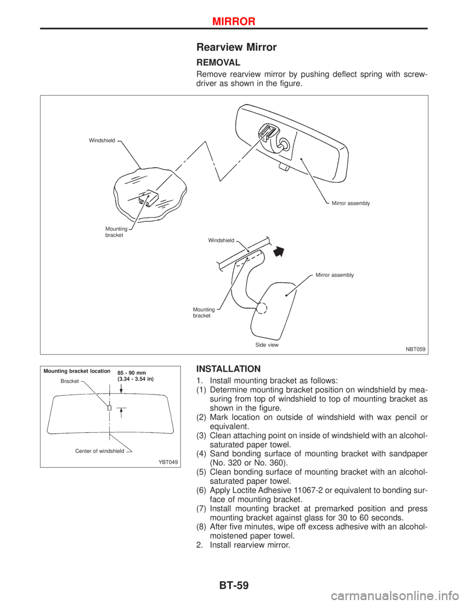
REMOVAL
Remove rearview mirror by pushing deflect spring with screw-
driver as shown in the figure.
INSTALLATION
1. Install mounting bracket as follows:
(1) Determine mounting bracket position on windshield by mea-
suring from top of windshield to top of mounting bracket as
shown in the figure.
(2) Mark location on outside of windshield with wax pencil or
equivalent.
(3) Clean attaching point on inside of windshield with an alcohol-
saturated paper towel.
(4) Sand bonding surface of mounting bracket with sandpaper
(No. 320 or No. 360).
(5) Clean bonding surface of mounting bracket with an alcohol-
saturated paper towel.
(6) Apply Loctite Adhesive 11067-2 or equivalent to bonding sur-
face of mounting bracket.
(7) Install mounting bracket at premarked position and press
mounting bracket against glass for 30 to 60 seconds.
(8) After five minutes, wipe off excess adhesive with an alcohol-
moistened paper towel.
2. Install rearview mirror.
NBT059 Windshield
Mirror assembly
Windshield Mounting
bracket
Mounting
bracket
Side viewMirror assembly
YBT049 Bracket
Center of windshield85-90mm
(3.34 - 3.54 in) Mounting bracket location
MIRROR
BT-59
Page 274 of 2267
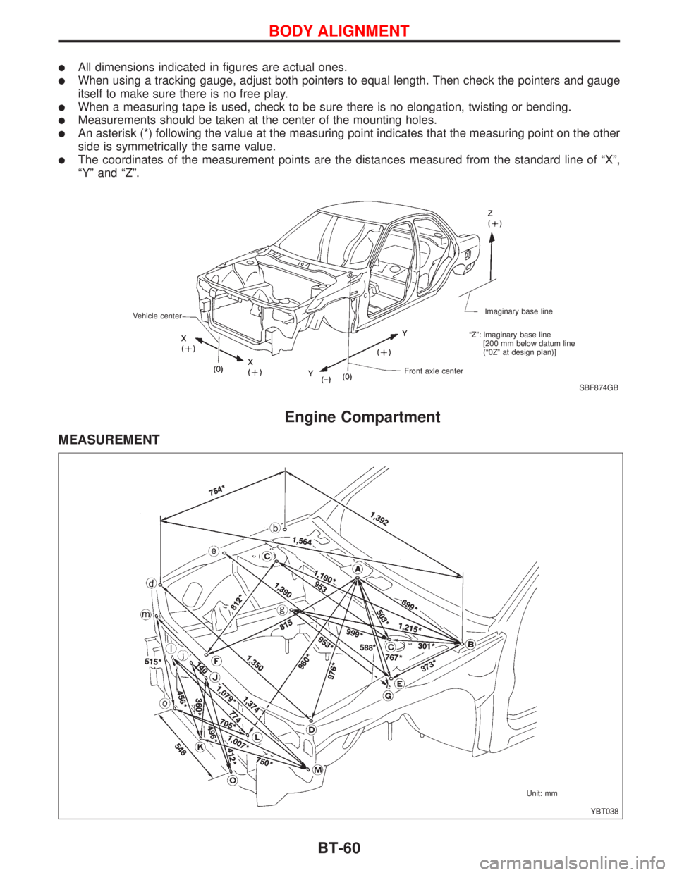
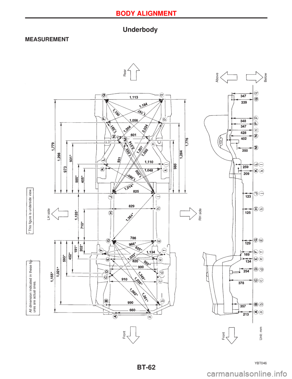
lAll dimensions indicated in figures are actual ones.
lWhen using a tracking gauge, adjust both pointers to equal length. Then check the pointers and gauge
itself to make sure there is no free play.
lWhen a measuring tape is used, check to be sure there is no elongation, twisting or bending.
lMeasurements should be taken at the center of the mounting holes.
lAn asterisk (*) following the value at the measuring point indicates that the measuring point on the other
side is symmetrically the same value.
lThe coordinates of the measurement points are the distances measured from the standard line of ªXº,
ªYº and ªZº.
Engine Compartment
MEASUREMENT
SBF874GB Imaginary base line
Front axle center Vehicle center
ªZº: Imaginary base line
[200 mm below datum line
(ª0Zº at design plan)]
YBT038 Unit: mm
BODY ALIGNMENT
BT-60
Page 275 of 2267
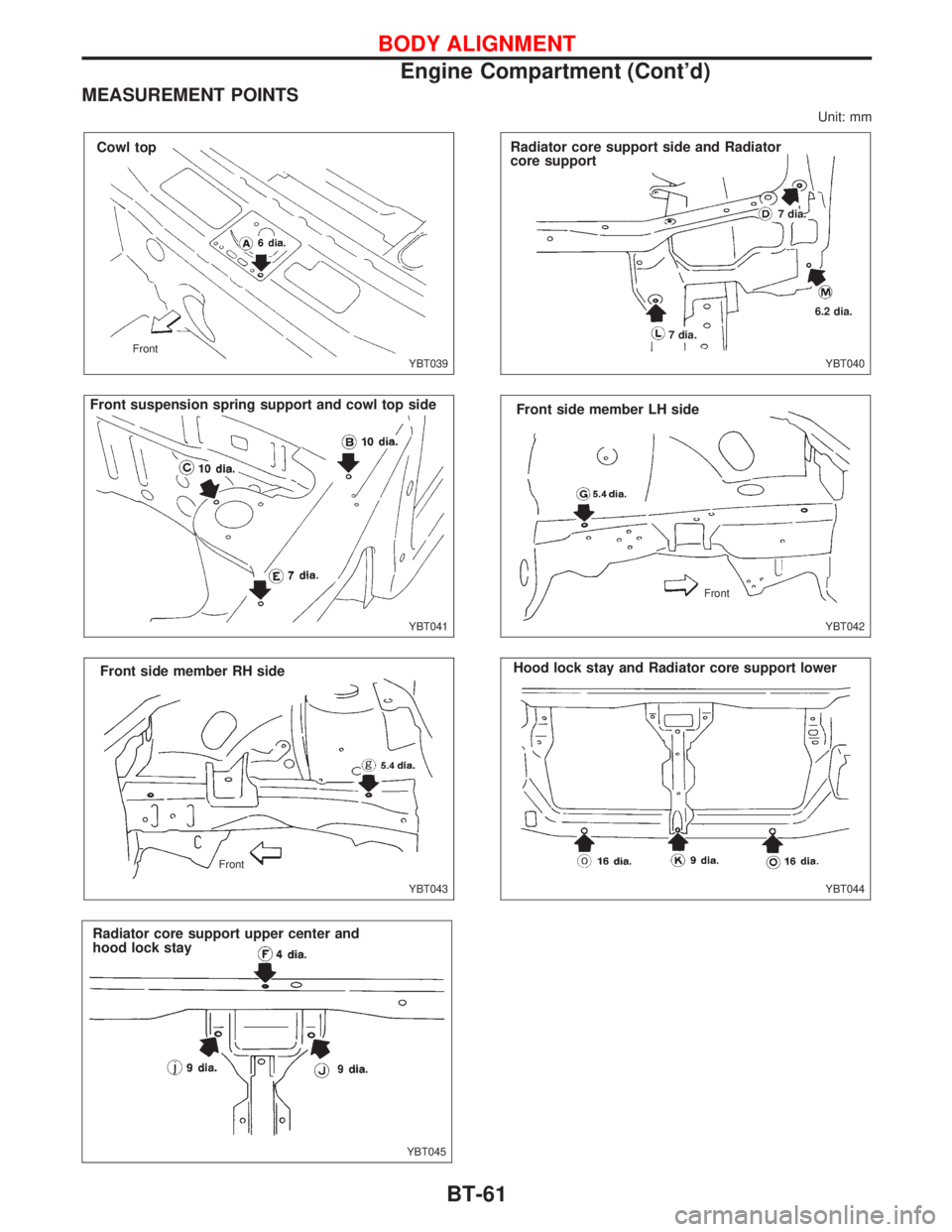
MEASUREMENT POINTS
Unit: mm
YBT039 Front
Cowl top
YBT041
.Front suspension spring support and cowl top side
.YBT043
Front side member RH side
Front
YBT045
Radiator core support upper center and
hood lock stay
YBT040
Radiator core support side and Radiator
core support
7 dia.
6.2 dia.
7 dia.
YBT042 Front
Front side member LH side
YBT044
Hood lock stay and Radiator core support lower
BODY ALIGNMENT
Engine Compartment (Cont'd)
BT-61
Page 276 of 2267
Underbody
MEASUREMENT
YBT046
Front
FrontRH sideLH side
Rear
Above All dimension indicated in these fig-
ures are actual ones.
* This figure is underside view.
Below Unit: mm
BODY ALIGNMENT
BT-62
Page 277 of 2267
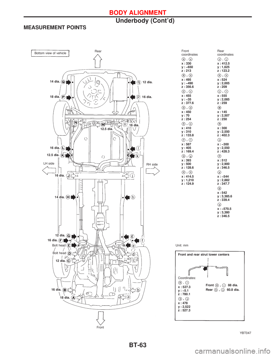
MEASUREMENT POINTS
YBT047 Rear
14 dia.
18 dia.12 dia.
16 dia.
12.5 dia.16 dia.
RH side 16 dia.
12.5 dia.
LH side
16 dia.
14 dia.
12 dia.
16 dia.
Bolt head
Bolt head
12 dia.
16 dia.
18 dia.Front and rear strut tower centers
Front
pR,pr88 dia.
Rear
pS,ps60.8 dia. Coordinates:
pR,prx : 527.3
y : þ5.1
z : 780.1
pS,psx : 478
y : 2,522
z : 527.3
FrontUnit: mmFront
coordinates
pA,pax : 330
y : þ650
z : 213
pB,pbx : 495
y : þ490
z : 356.6
pC,pcx : 455
y : þ35
z : 377.6
pD,pdx : 450
y:70
z : 254
pE,pex : 410
y : 310
z : 133.8
pF,pfx : 587
y : 405
z : 169.4
pG,pgx : 393
y : 500
z : 128.6
pH,phx : 414.5
y : 1,210
z : 124.9Rear
coordinates
pJ,pjx : 412.5
y : 1,625
z : 123.2
pK,pkx : 524
y : 2,005
z : 209
pL,plx : 555
y : 2,085
z : 259
pMx : 145
y : 2,507
z : 250
pNx : 300
y : 2,550
z : 402.3
pnx : þ300
y : 2,550
z : 428.3
pPx : 512
y : 2,900
z : 346.5
ppx : þ544
y : 2,882
z : 347.7
pQx : 542
y : 3,385.6
z : 339.4
pqx : þ570.5
y : 3,380
z : 346.5 Bottom view of vehicle
BODY ALIGNMENT
Underbody (Cont'd)
BT-63
Page 278 of 2267
NOTE
BODY ALIGNMENT
BT-64
Page 279 of 2267
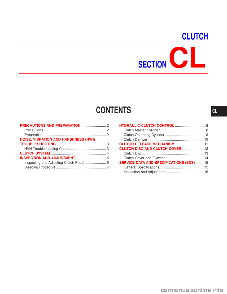
CLUTCH
SECTION
CL
CONTENTS
PRECAUTIONS AND PREPARATION.......................... 2
Precautions ................................................................ 2
Preparation ................................................................ 2
NOISE, VIBRATION AND HARSHNESS (NVH)
TROUBLESHOOTING................................................... 3
NVH Troubleshooting Chart....................................... 3
CLUTCH SYSTEM......................................................... 4
INSPECTION AND ADJUSTMENT............................... 5
Inspecting and Adjusting Clutch Pedal ...................... 5
Bleeding Procedure ................................................... 7HYDRAULIC CLUTCH CONTROL............................... 8
Clutch Master Cylinder .............................................. 8
Clutch Operating Cylinder ......................................... 9
Clutch Damper ......................................................... 10
CLUTCH RELEASE MECHANISM.............................. 11
CLUTCH DISC AND CLUTCH COVER...................... 13
Clutch Disc............................................................... 13
Clutch Cover and Flywheel ..................................... 14
SERVICE DATA AND SPECIFICATIONS (SDS)........ 15
General Specifications ............................................. 15
Inspection and Adjustment ...................................... 16
CL
Page 280 of 2267
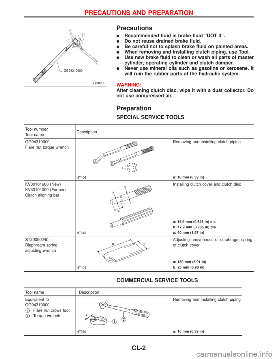
Precautions
lRecommended fluid is brake fluid ªDOT 4º.
lDo not reuse drained brake fluid.
lBe careful not to splash brake fluid on painted areas.
lWhen removing and installing clutch piping, use Tool.
lUse new brake fluid to clean or wash all parts of master
cylinder, operating cylinder and clutch damper.
lNever use mineral oils such as gasoline or kerosene. It
will ruin the rubber parts of the hydraulic system.
WARNING:
After cleaning clutch disc, wipe it with a dust collector. Do
not use compressed air.
Preparation
SPECIAL SERVICE TOOLS
COMMERCIAL SERVICE TOOLS
SBR820B GG94310000
Tool number
Tool nameDescription
GG94310000
Flare nut torque wrench
NT406
Removing and installing clutch piping
a: 10 mm (0.39 in)
KV30101600 (New)
KV30101000 (Former)
Clutch aligning bar
NT645
Installing clutch cover and clutch disc
a: 15.9 mm (0.626 in) dia.
b: 17.9 mm (0.705 in) dia.
c: 40 mm (1.57 in)
ST20050240
Diaphragm spring
adjusting wrench
NT404
Adjusting unevenness of diaphragm spring
of clutch cover
a: 150 mm (5.91 in)
b: 25 mm (0.98 in)
Tool name Description
Equivalent to
GG94310000
p1Flare nut crows foot
p2Torque wrench
NT360
Removing and installing clutch piping
a: 10 mm (0.39 in)
PRECAUTIONS AND PREPARATION
CL-2
Trending: bulb, alarm, fuel pump, air suspension, reset, tow bar, seat adjustment
