NISSAN TEANA 2008 Service Manual
Manufacturer: NISSAN, Model Year: 2008, Model line: TEANA, Model: NISSAN TEANA 2008Pages: 5121, PDF Size: 69.03 MB
Page 2571 of 5121

HA-2
LOW-PRESSURE PIPE .....................................42
Exploded View ........................................................42
Removal and Installation ........................................42
HIGH-PRESSURE PIPE ....................................44
Exploded View ........................................................44
Removal and Installation ........................................44
CONDENSER ....................................................46
Exploded View ........................................................46
Removal and Installation ........................................46
CONDENSER PIPE ASSEMBLY ......................48
Exploded View ........................................................48
Removal and Installation ........................................48
LIQUID TANK ....................................................50
Exploded View ........................................................50
Removal and Installation ........................................50
REFRIGERANT PRESSURE SENSOR ............51
Exploded View ........................................................51
Removal and Installation ........................................51
EVAPORATOR ..................................................52
Exploded View ........................................................52
Removal and Installation .........................................53
EVAPORATOR PIPE ASSEMBLY ....................54
Exploded View ........................................................54
Removal and Installation .........................................55
EXPANSION VALVE .........................................57
Exploded View ........................................................57
Removal and Installation .........................................58
SERVICE DATA AND SPECIFICATIONS
(SDS) ..........................................................
59
SERVICE DATA AND SPECIFICATIONS
(SDS) .................................................................
59
Compressor ............................................................59
Lubricant .................................................................59
Refrigerant ..............................................................59
Engine Idling Speed ................................................59
Belt Tension ............................................................59
Page 2572 of 5121
DIAGNOSIS AND REPAIR WORK FLOW
HA-3
< BASIC INSPECTION >
C
D
E
F
G
H
J
K
L
MA
B
HA
N
O
P
BASIC INSPECTION
DIAGNOSIS AND REPAIR WORK FLOW
Work FlowINFOID:0000000003795801
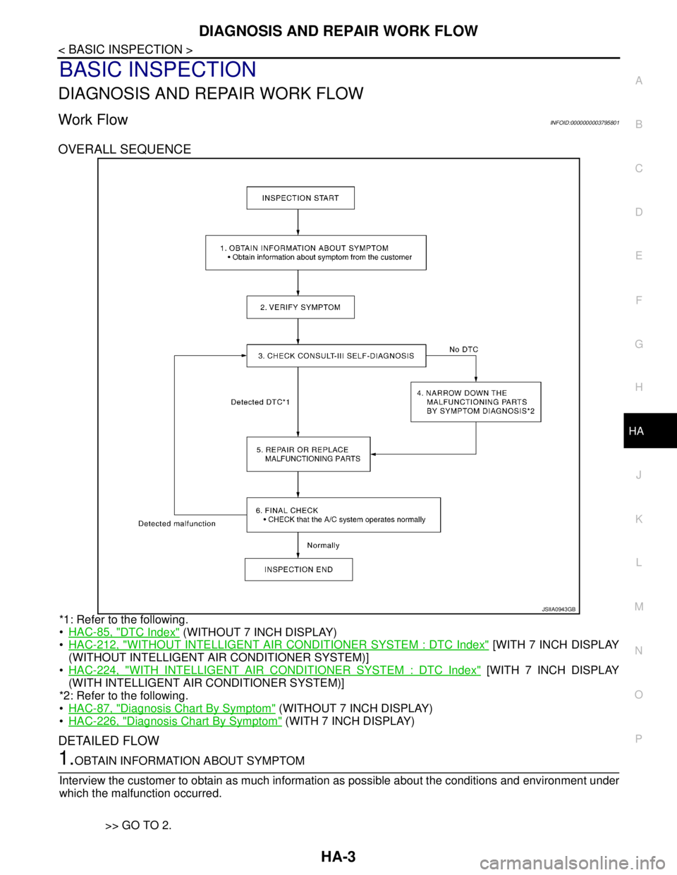
OVERALL SEQUENCE
*1: Refer to the following.
•HAC-85, "
DTC Index" (WITHOUT 7 INCH DISPLAY)
HAC-212, "
WITHOUT INTELLIGENT AIR CONDITIONER SYSTEM : DTC Index" [WITH 7 INCH DISPLAY
(WITHOUT INTELLIGENT AIR CONDITIONER SYSTEM)]
HAC-224, "
WITH INTELLIGENT AIR CONDITIONER SYSTEM : DTC Index" [WITH 7 INCH DISPLAY
(WITH INTELLIGENT AIR CONDITIONER SYSTEM)]
*2: Refer to the following.
HAC-87, "
Diagnosis Chart By Symptom" (WITHOUT 7 INCH DISPLAY)
HAC-226, "
Diagnosis Chart By Symptom" (WITH 7 INCH DISPLAY)
DETAILED FLOW
1.OBTAIN INFORMATION ABOUT SYMPTOM
Interview the customer to obtain as much information as possible about the conditions and environment under
which the malfunction occurred.
>> GO TO 2.
JSIIA0943GB
Page 2573 of 5121
HA-4
< BASIC INSPECTION >
DIAGNOSIS AND REPAIR WORK FLOW
2.VERIFY SYMPTOM
Verify the symptom with operational check based on the information obtained from the customer. Refer to the
following.
HAC-8, "
Description & Inspection" (WITHOUT 7 INCH DISPLAY)
HAC-108, "
WITHOUT INTELLIGENT AIR CONDITIONER SYSTEM : Description & Inspection" [WITH 7
INCH DISPLAY (WITHOUT INTELLIGENT AIR CONDITIONER SYSTEM)]
HAC-112, "
WITH INTELLIGENT AIR CONDITIONER SYSTEM : Description & Inspection" [WITH 7 INCH
DISPLAY (WITH INTELLIGENT AIR CONDITIONER SYSTEM)]
>> GO TO 3.
3.CHECK WITH SELF-DIAGNOSIS FUNCTION OF CONSULT-III
Using CONSULT-III, perform “SELF-DIAGNOSIS RESULTS” of HVAC. Refer to the following.
HAC-85, "
DTC Index" (WITHOUT 7 INCH DISPLAY)
HAC-212, "
WITHOUT INTELLIGENT AIR CONDITIONER SYSTEM : DTC Index" [WITH 7 INCH DISPLAY
(WITHOUT INTELLIGENT AIR CONDITIONER SYSTEM)]
HAC-224, "
WITH INTELLIGENT AIR CONDITIONER SYSTEM : DTC Index" [WITH 7 INCH DISPLAY
(WITH INTELLIGENT AIR CONDITIONER SYSTEM)]
Are self
-diagnosis results normal?
YES >> GO TO 4.
NO >> GO TO 5.
4.NARROW DOWN THE MALFUNCTIONING PARTS BY SYMPTOM DIAGNOSIS
Perform symptom diagnosis and narrow down the malfunctioning parts. Refer to the following.
HAC-87, "
Diagnosis Chart By Symptom" (WITHOUT 7 INCH DISPLAY)
HAC-226, "
Diagnosis Chart By Symptom" (WITH 7 INCH DISPLAY)
>> GO TO 5.
5.REPAIR OR REPLACE
Repair or replace malfunctioning parts.
NOTE:
If DTC is displayed, erase DTC after repairing or replacing malfunctioning parts.
>> GO TO 6.
6.FINAL CHECK
Check that the A/C system operates normally.
Is the inspection result normal?
YES >> INSPECTION END
NO >> GO TO 3.
Page 2574 of 5121
REFRIGERATION SYSTEM
HA-5
< FUNCTION DIAGNOSIS >
C
D
E
F
G
H
J
K
L
MA
B
HA
N
O
P
FUNCTION DIAGNOSIS
REFRIGERATION SYSTEM
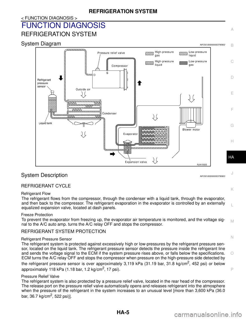
System DiagramINFOID:0000000003795802
System DescriptionINFOID:0000000003795803
REFRIGERANT CYCLE
Refrigerant Flow
The refrigerant flows from the compressor, through the condenser with a liquid tank, through the evaporator,
and then back to the compressor. The refrigerant evaporation in the evaporator is controlled by an externally
equalized expansion valve, located at dash panels.
Freeze Protection
To prevent the evaporator from freezing up, the evaporator air temperature is monitored, and the voltage sig-
nal to the A/C auto amp. turns the A/C relay OFF and stops the compressor.
REFRIGERANT SYSTEM PROTECTION
Refrigerant Pressure Sensor
The refrigerant system is protected against excessively high or low-pressures by the refrigerant pressure sen-
sor, located on the liquid tank. The refrigerant pressure sensor detects the pressure inside the refrigerant line
and sends the voltage signal to the ECM if the system pressure rises above, or falls below the specifications.
ECM turns the A/C relay OFF and stops the compressor when pressure on the high-pressure side detected by
the refrigerant pressure sensor is over approximately 3,119 kPa (31.19 bar, 31.8 kg/cm
2, 452 psi) or below
approximately 118 kPa (1.18 bar, 1.2 kg/cm
2, 17 psi).
Pressure Relief Valve
The refrigerant system is also protected by a pressure relief valve, located in the rear head of the compressor.
The release port on the pressure relief valve automatically opens and releases refrigerant into the atmosphere
when the pressure of the refrigerant in the system increases to an unusual level [more than 3,600 kPa (36.0
bar, 36.7 kg/cm
2, 522 psi)].
RJIA1552E
Page 2575 of 5121
HA-6
< FUNCTION DIAGNOSIS >
REFRIGERATION SYSTEM
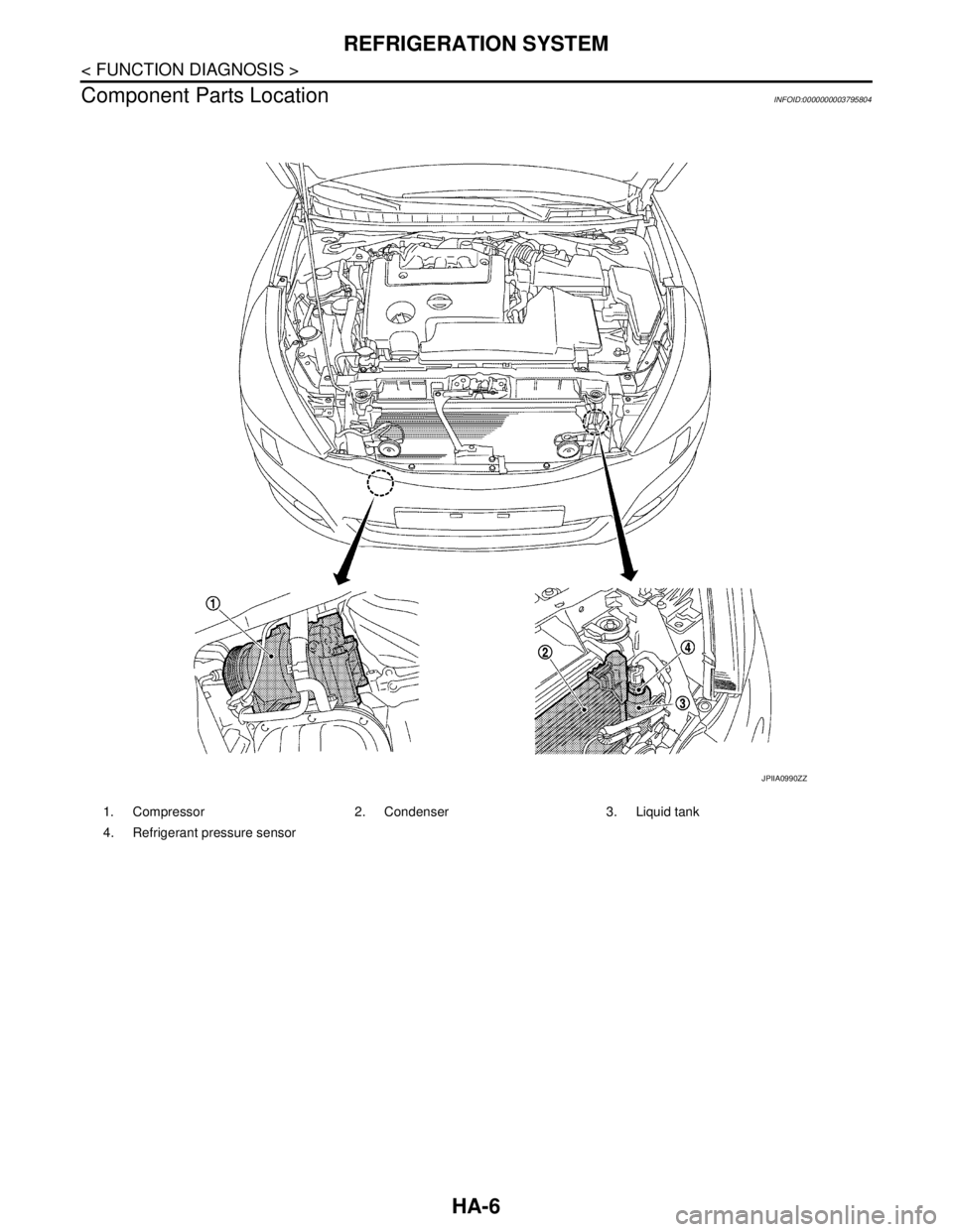
Component Parts Location
INFOID:0000000003795804
1. Compressor 2. Condenser 3. Liquid tank
4. Refrigerant pressure sensor
JPIIA0990ZZ
Page 2576 of 5121
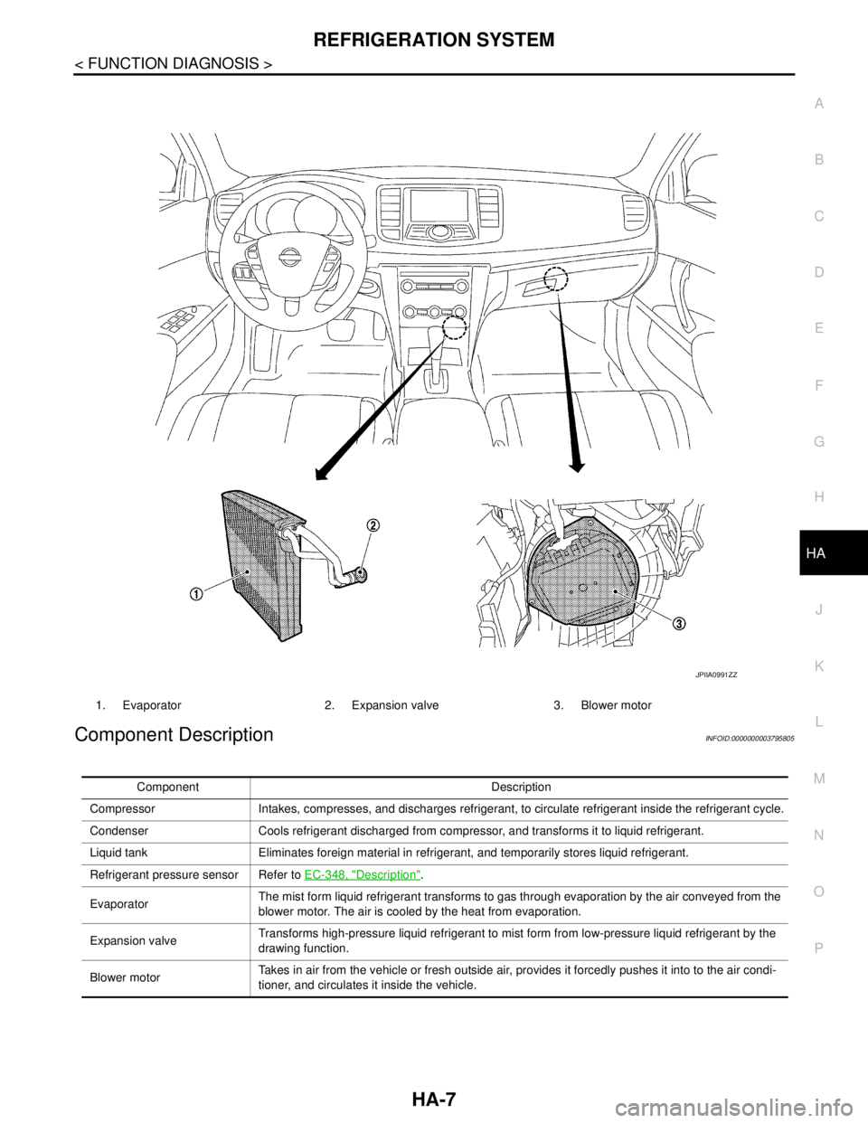
REFRIGERATION SYSTEM
HA-7
< FUNCTION DIAGNOSIS >
C
D
E
F
G
H
J
K
L
MA
B
HA
N
O
P
Component DescriptionINFOID:0000000003795805
1. Evaporator 2. Expansion valve 3. Blower motor
JPIIA0991ZZ
Component Description
Compressor Intakes, compresses, and discharges refrigerant, to circulate refrigerant inside the refrigerant cycle.
Condenser Cools refrigerant discharged from compressor, and transforms it to liquid refrigerant.
Liquid tank Eliminates foreign material in refrigerant, and temporarily stores liquid refrigerant.
Refrigerant pressure sensor Refer to EC-348, "
Description".
EvaporatorThe mist form liquid refrigerant transforms to gas through evaporation by the air conveyed from the
blower motor. The air is cooled by the heat from evaporation.
Expansion valveTransforms high-pressure liquid refrigerant to mist form from low-pressure liquid refrigerant by the
drawing function.
Blower motorTakes in air from the vehicle or fresh outside air, provides it forcedly pushes it into to the air condi-
tioner, and circulates it inside the vehicle.
Page 2577 of 5121
HA-8
< SYMPTOM DIAGNOSIS >
REFRIGERATION SYSTEM SYMPTOMS
SYMPTOM DIAGNOSIS
REFRIGERATION SYSTEM SYMPTOMS
Trouble Diagnosis For Unusual PressureINFOID:0000000003795806
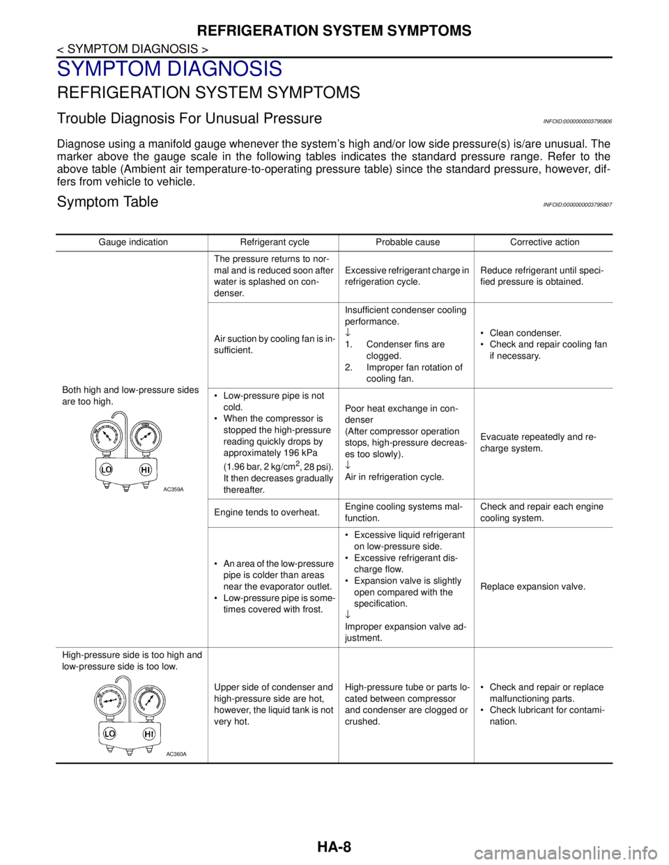
Diagnose using a manifold gauge whenever the system’s high and/or low side pressure(s) is/are unusual. The
marker above the gauge scale in the following tables indicates the standard pressure range. Refer to the
above table (Ambient air temperature-to-operating pressure table) since the standard pressure, however, dif-
fers from vehicle to vehicle.
Symptom TableINFOID:0000000003795807
Gauge indication Refrigerant cycle Probable cause Corrective action
Both high and low-pressure sides
are too high.The pressure returns to nor-
mal and is reduced soon after
water is splashed on con-
denser.Excessive refrigerant charge in
refrigeration cycle.Reduce refrigerant until speci-
fied pressure is obtained.
Air suction by cooling fan is in-
sufficient.Insufficient condenser cooling
performance.
↓
1. Condenser fins are
clogged.
2. Improper fan rotation of
cooling fan. Clean condenser.
Check and repair cooling fan
if necessary.
Low-pressure pipe is not
cold.
When the compressor is
stopped the high-pressure
reading quickly drops by
approximately 196 kPa
(1.96 bar, 2 kg/cm
2, 28 psi).
It then decreases gradually
thereafter.Poor heat exchange in con-
denser
(After compressor operation
stops, high-pressure decreas-
es too slowly).
↓
Air in refrigeration cycle.Evacuate repeatedly and re-
charge system.
Engine tends to overheat.Engine cooling systems mal-
function.Check and repair each engine
cooling system.
An area of the low-pressure
pipe is colder than areas
near the evaporator outlet.
Low-pressure pipe is some-
times covered with frost. Excessive liquid refrigerant
on low-pressure side.
Excessive refrigerant dis-
charge flow.
Expansion valve is slightly
open compared with the
specification.
↓
Improper expansion valve ad-
justment.Replace expansion valve.
High-pressure side is too high and
low-pressure side is too low.
Upper side of condenser and
high-pressure side are hot,
however, the liquid tank is not
very hot.High-pressure tube or parts lo-
cated between compressor
and condenser are clogged or
crushed. Check and repair or replace
malfunctioning parts.
Check lubricant for contami-
nation.
AC359A
AC360A
Page 2578 of 5121
REFRIGERATION SYSTEM SYMPTOMS
HA-9
< SYMPTOM DIAGNOSIS >
C
D
E
F
G
H
J
K
L
MA
B
HA
N
O
P
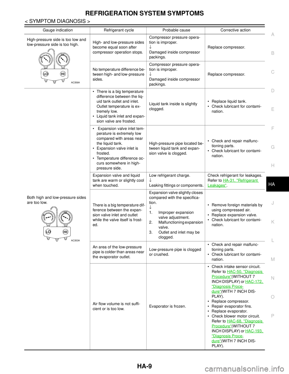
High-pressure side is too low and
low-pressure side is too high.High- and low-pressure sides
become equal soon after
compressor operation stops.Compressor pressure opera-
tion is improper.
↓
Damaged inside compressor
packings.Replace compressor.
No temperature difference be-
tween high- and low-pressure
sides.Compressor pressure opera-
tion is improper.
↓
Damaged inside compressor
packings.Replace compressor.
Both high and low-pressure sides
are too low. There is a big temperature
difference between the liq-
uid tank outlet and inlet.
Outlet temperature is ex-
tremely low.
Liquid tank inlet and expan-
sion valve are frosted.Liquid tank inside is slightly
clogged. Replace liquid tank.
Check lubricant for contami-
nation.
Expansion valve inlet tem-
perature is extremely low
compared with areas near
the liquid tank.
Expansion valve inlet is
frosted.
Temperature difference oc-
curs somewhere in high-
pressure side.High-pressure pipe located be-
tween liquid tank and expan-
sion valve is clogged. Check and repair malfunc-
tioning parts.
Check lubricant for contami-
nation.
Expansion valve and liquid
tank are warm or slightly cool
when touched.Low refrigerant charge.
↓
Leaking fittings or components.Check refrigerant for leakages.
Refer to HA-31, "
Refrigerant
Leakages".
There is a big temperature dif-
ference between the expan-
sion valve inlet and outlet
while the valve itself is frost-
ed.Expansion valve slightly closes
compared with the specifica-
tion.
↓
1. Improper expansion
valve adjustment.
2. Malfunctioning expansion
valve.
3. Outlet and inlet may be
clogged. Remove foreign materials by
using compressed air.
Replace expansion valve.
Check lubricant for contami-
nation.
An area of the low-pressure
pipe is colder than areas near
the evaporator outlet.Low-pressure pipe is clogged
or crushed. Check and repair malfunc-
tioning parts.
Check lubricant for contami-
nation.
Air flow volume is not suffi-
cient or is too low.Evaporator is frozen. Check intake sensor circuit.
Refer to HAC-50, "
Diagnosis
Procedure"(WITHOUT 7
INCH DISPLAY) or HAC-172,
"Diagnosis Proce-
dure"(WITH 7 INCH DIS-
PLAY).
Replace compressor.
Repair evaporator fins.
Replace evaporator.
Check blower motor circuit.
Refer to HAC-68, "
Diagnosis
Procedure"(WITHOUT 7
INCH DISPLAY) or HAC-193,
"Diagnosis Proce-
dure"(WITH 7 INCH DIS-
PLAY). Gauge indication Refrigerant cycle Probable cause Corrective action
AC356A
AC353A
Page 2579 of 5121

HA-10
< SYMPTOM DIAGNOSIS >
REFRIGERATION SYSTEM SYMPTOMS
Low-pressure side sometimes be-
comes negative. Air conditioning system
does not function and does
not cyclically cool the com-
partment air.
The system constantly
functions for a period of
time after compressor is
stopped and restarted.Refrigerant does not discharge
cyclically.
↓
Moisture is frozen at expansion
valve outlet and inlet.
↓
Water is mixed with refrigerant. Drain water from refrigerant
or replace refrigerant.
Replace liquid tank.
Low-pressure side becomes nega-
tive.
Liquid tank or front/rear side
of expansion valve’s pipe is
frosted or wet with dew.High-pressure side is closed
and refrigerant does not flow.
↓
Expansion valve or liquid tank
is frosted.Do not use the system until the
frost has melted. Start it again to
check whether or not the mal-
function is caused by water or
foreign materials.
Cooling is initially okay if wa-
ter is the cause. Then the wa-
ter freezes, which causes a
blockage. Drain water from
refrigerant or replace refriger-
ant.
If due to foreign materials, re-
move expansion valve and
the particles with dry com-
pressed air (not shop air.)
Replace expansion valve if
either of the above methods
cannot correct the malfunc-
tion.
Replace liquid tank.
Check lubricant for contami-
nation. Gauge indication Refrigerant cycle Probable cause Corrective action
AC354A
AC362A
Page 2580 of 5121
COMPRESSOR SYSTEM SYMPTOMS
HA-11
< SYMPTOM DIAGNOSIS >
C
D
E
F
G
H
J
K
L
MA
B
HA
N
O
P
COMPRESSOR SYSTEM SYMPTOMS
Symptom TableINFOID:0000000003795808
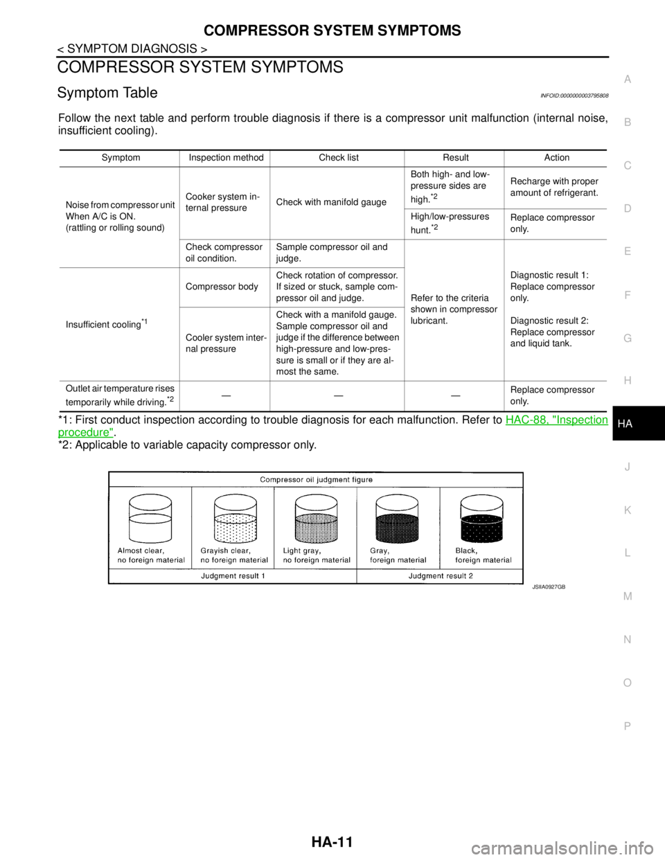
Follow the next table and perform trouble diagnosis if there is a compressor unit malfunction (internal noise,
insufficient cooling).
*1: First conduct inspection according to trouble diagnosis for each malfunction. Refer to HAC-88, "
Inspection
procedure".
*2: Applicable to variable capacity compressor only.
Symptom Inspection method Check list Result Action
Noise from compressor unit
When A/C is ON.
(rattling or rolling sound)Cooker system in-
ternal pressureCheck with manifold gaugeBoth high- and low-
pressure sides are
high.
*2
Recharge with proper
amount of refrigerant.
High/low-pressures
hunt.
*2Replace compressor
only.
Check compressor
oil condition.Sample compressor oil and
judge.
Refer to the criteria
shown in compressor
lubricant.Diagnostic result 1:
Replace compressor
only.
Diagnostic result 2:
Replace compressor
and liquid tank. Insufficient cooling
*1
Compressor bodyCheck rotation of compressor.
If sized or stuck, sample com-
pressor oil and judge.
Cooler system inter-
nal pressureCheck with a manifold gauge.
Sample compressor oil and
judge if the difference between
high-pressure and low-pres-
sure is small or if they are al-
most the same.
Outlet air temperature rises
temporarily while driving.
*2—— —Replace compressor
only.
JSIIA0927GB