NISSAN TEANA 2014 Service Manual
Manufacturer: NISSAN, Model Year: 2014, Model line: TEANA, Model: NISSAN TEANA 2014Pages: 4801, PDF Size: 51.2 MB
Page 351 of 4801

CHG-6
< SYSTEM DESCRIPTION >
COMPONENT PARTS
QR25DE : Component Description
INFOID:0000000009460647
VQ35DE
Component part Description
Generator (IC regulator) The IC regulator controls the power generation voltage by the tar-
get power generation voltage based on the received PWM com-
mand signal.
When there is no PWM command signal, the generator performs
the normal power generation according to the characteristic of the
IC regulator.
ECM The battery current sensor detects the charging/discharging cur-
rent of the battery. The ECM judges the battery condition based on
this signal.
The ECM judges whether to request more output via the power
generation voltage variable control according to the battery condi-
tion.
When performing the power generation voltage variable control,
the ECM calculates the target power generation voltage according
to the battery condition and sends the calculated value as the pow-
er generation command value to the IPDM E/R.
IPDM E/R The IPDM E/R converts the received power generation command
value into a pulse width modulated (PWM) command signal and
sends it to the IC regulator.
Combination meter (c harge warning lamp) The IC regulator warning function activates to illuminate the
charge warning lamp if any of the following symptoms occur while
generator is operating:
·Excessive voltage is produced.
·No voltage is produced.
Battery current sensor The battery current sensor is located on the negative battery cable
terminal. The battery current sensor detects the charging/dis-
charging current of the battery and sends a voltage signal to the
ECM according to the current value detected.
Revision: November 20132014 Altima NAMRevision: November 20132014 Altima NAM
Page 352 of 4801

CHG
COMPONENT PARTSCHG-7
< SYSTEM DESCRIPTION >
C
D E
F
G H
I
J
K L
B
A
O P
N
VQ35DE : Component Parts LocationINFOID:0000000009460648
AWMIA1304ZZ
1. Generator 2. IPDM E/R 3. ECM
4. Battery current sensor 5. Charge warning lamp indicator
Revision: November 20132014 Altima NAMRevision: November 20132014 Altima NAM
Page 353 of 4801

CHG-8
< SYSTEM DESCRIPTION >
COMPONENT PARTS
VQ35DE : Component Description
INFOID:0000000009460649
Component part Description
Generator (IC regulator) The IC regulator controls the power generation voltage by the tar-
get power generation voltage based on the received PWM com-
mand signal.
When there is no PWM command signal, the generator performs
the normal power generation according to the characteristic of the
IC regulator.
ECM The battery current sensor detects the charging/discharging cur-
rent of the battery. The ECM judges the battery condition based on
this signal.
The ECM judges whether to request more output via the power
generation voltage variable control according to the battery condi-
tion.
When performing the power generation voltage variable control,
the ECM calculates the target power generation voltage according
to the battery condition and sends the calculated value as the pow-
er generation command value to the IPDM E/R.
IPDM E/R The IPDM E/R converts the received power generation command
value into a pulse width modulated (PWM) command signal and
sends it to the IC regulator.
Combination meter (c harge warning lamp) The IC regulator warning function activates to illuminate the
charge warning lamp if any of the following symptoms occur while
generator is operating:
·Excessive voltage is produced.
·No voltage is produced.
Battery current sensor The battery current sensor is located on the negative battery cable
terminal. The battery current sensor detects the charging/dis-
charging current of the battery and sends a voltage signal to the
ECM according to the current value detected.
Revision: November 20132014 Altima NAMRevision: November 20132014 Altima NAM
Page 354 of 4801
CHG
CHARGING SYSTEMCHG-9
< SYSTEM DESCRIPTION >
C
D E
F
G H
I
J
K L
B
A
O P
N
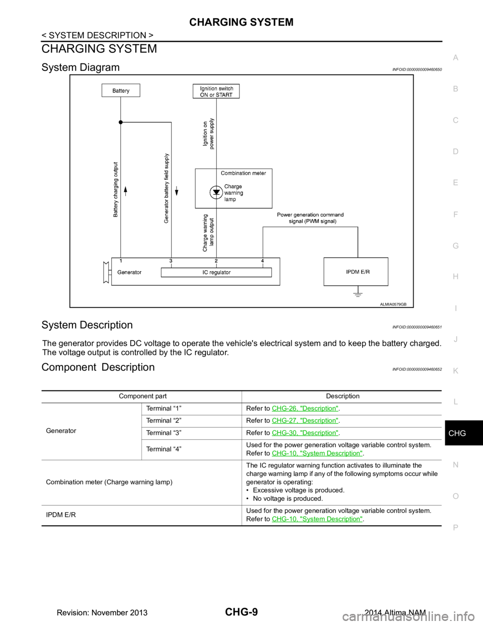
CHARGING SYSTEM
System DiagramINFOID:0000000009460650
System DescriptionINFOID:0000000009460651
The generator provides DC voltage to operate the vehicl
e's electrical system and to keep the battery charged.
The voltage output is controlled by the IC regulator.
Component DescriptionINFOID:0000000009460652
ALMIA0579GB
Component part Description
Generator Terminal “1” Refer to
CHG-26, "Description"
.
Terminal “2” Refer to CHG-27, "Description"
.
Terminal “3” Refer to CHG-30, "Description"
.
Terminal “4” Used for the power generation voltage variable control system.
Refer to CHG-10, "Syste m Description"
.
Combination meter (C harge warning lamp) The IC regulator warning function activates to illuminate the
charge warning lamp if any of the following symptoms occur while
generator is operating:
• Excessive voltage is produced.
• No voltage is produced.
IPDM E/R Used for the power generation voltage variable control system.
Refer to CHG-10, "Syste m Description"
.
Revision: November 20132014 Altima NAMRevision: November 20132014 Altima NAM
Page 355 of 4801

CHG-10
< SYSTEM DESCRIPTION >
POWER GENERATION VOLTAGE VARIABLE CONTROL SYSTEM
POWER GENERATION VOLTAGE VARIABLE CONTROL SYSTEM
System DiagramINFOID:0000000009460653
System DescriptionINFOID:0000000009460654
Power generation variable voltage control system has been adopted. By varying the voltage to the generator,
engine load due to power generation of the generator is reduced and fuel consumption is decreased.
NOTE:
When any malfunction is detected in the power generat ion variable voltage control system, power generation
is performed according to the characteristic of the IC regulator in the generator.
Component DescriptionINFOID:0000000009460655
ALMIA0566GB
Component part Description
Generator (IC regulator) The IC regulator controls the power generation voltage by the tar-
get power generation voltage based on the received PWM com-
mand signal.
When there is no PWM command signal, the generator performs
the normal power generation according to the characteristic of the
IC regulator.
ECM The battery current sensor detects the charging/discharging cur-
rent of the battery. The ECM judges the battery condition based on
this signal.
The ECM judges whether to request more output via the power
generation voltage variable control according to the battery condi-
tion.
When performing the power generation voltage variable control,
the ECM calculates the target power generation voltage according
to the battery condition and sends the calculated value as the pow-
er generation command value to the IPDM E/R.
IPDM E/R The IPDM E/R converts the received power generation command
value into a pulse width modulated (PWM) command signal and
sends it to the IC regulator.
Revision: November 20132014 Altima NAMRevision: November 20132014 Altima NAM
Page 356 of 4801

CHG
POWER GENERATION VOLTAGE VARIABLE CONTROL SYSTEM
CHG-11
< SYSTEM DESCRIPTION >
C
D E
F
G H
I
J
K L
B
A
O P
N
Combination meter (c
harge warning lamp) The IC regulator warning function activates to illuminate the
charge warning lamp if any of the following symptoms occur while
generator is operating:
• Excessive voltage is produced.
• No voltage is produced.
Battery current sensor The battery current sensor is located on the battery cable terminal.
The battery current sensor detects the charging/discharging cur-
rent of the battery and sends a voltage signal to the ECM accord-
ing to the current value detected.
Component part Description
Revision: November 20132014 Altima NAMRevision: November 20132014 Altima NAM
Page 357 of 4801
CHG-12
< WIRING DIAGRAM >
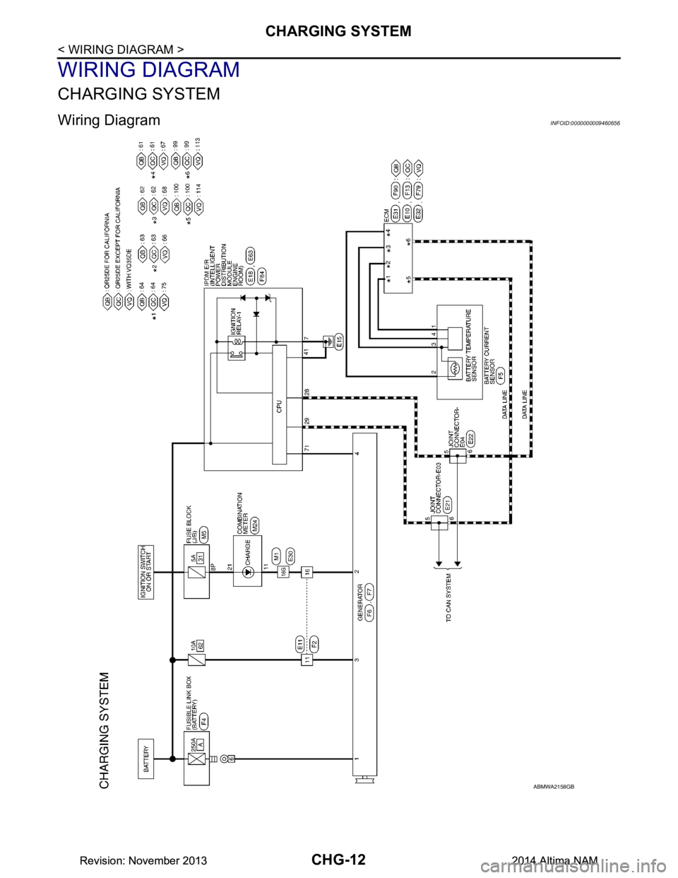
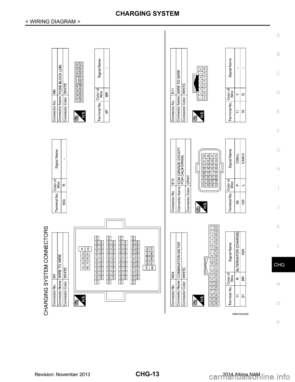
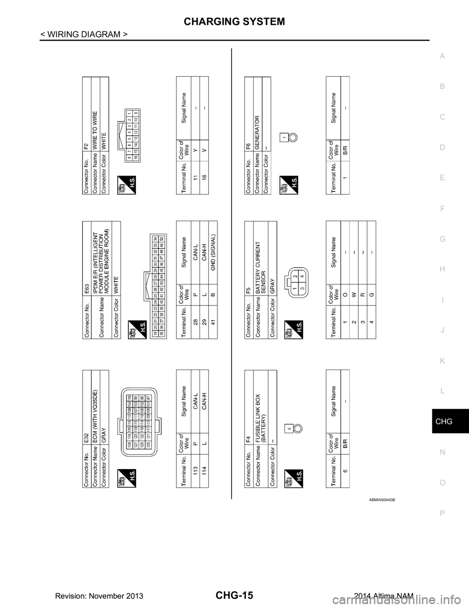
CHARGING SYSTEM
WIRING DIAGRAM
CHARGING SYSTEM
Wiring Diagram INFOID:0000000009460656
ABMWA2158GB
Revision: November 20132014 Altima NAMRevision: November 20132014 Altima NAM
Page 358 of 4801
CHG
CHARGING SYSTEMCHG-13
< WIRING DIAGRAM >
C
D E
F
G H
I
J
K L
B
A
O P
N
ABMIA5093GB
Revision: November 20132014 Altima NAMRevision: November 20132014 Altima NAM
Page 359 of 4801
CHG-14
< WIRING DIAGRAM >
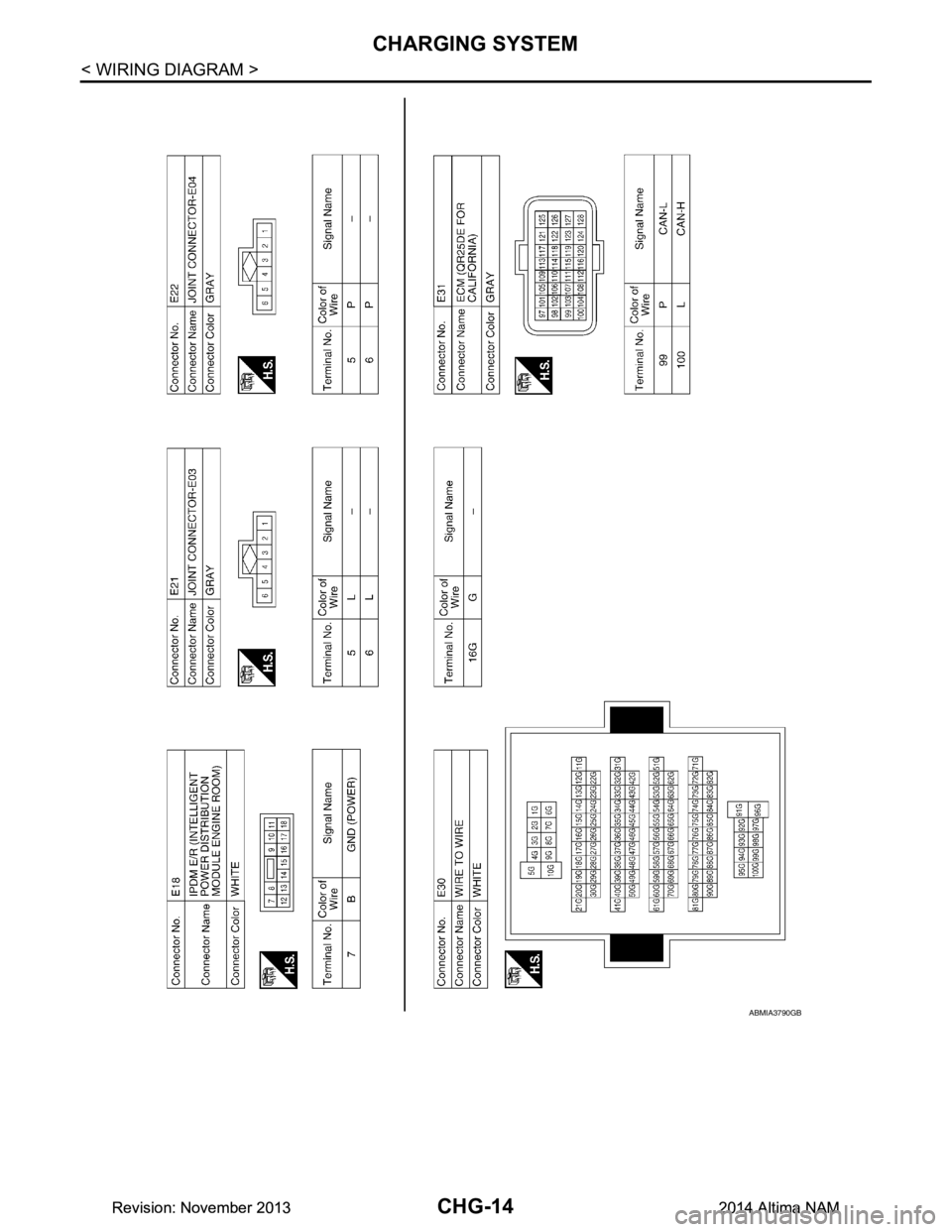
CHARGING SYSTEM
ABMIA3790GB
Revision: November 20132014 Altima NAMRevision: November 20132014 Altima NAM
Page 360 of 4801
CHG
CHARGING SYSTEMCHG-15
< WIRING DIAGRAM >
C
D E
F
G H
I
J
K L
B
A
O P
N
ABMIA5094GB
Revision: November 20132014 Altima NAMRevision: November 20132014 Altima NAM