NISSAN TERRANO 2004 Service Repair Manual
Manufacturer: NISSAN, Model Year: 2004, Model line: TERRANO, Model: NISSAN TERRANO 2004Pages: 1833, PDF Size: 53.42 MB
Page 1411 of 1833
Precautions for Service Equipment
RECOVERY/RECYCLING/RECHARGING EQUIPMENT
Be certain to follow the manufacturers instructions for machine
operation and machine maintenance. Never introduce any refriger-
ant other than that specified into the machine.
ELECTRONIC LEAK DETECTOR
Be certain to follow the manufactures instructions for tester opera-
tion and tester maintenance.
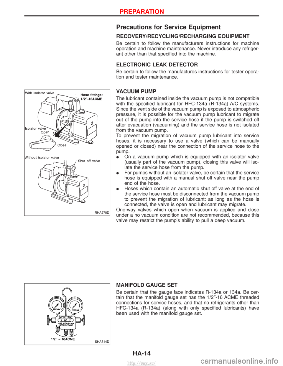
VACUUM PUMP
The lubricant contained inside the vacuum pump is not compatible
with the specified lubricant for HFC-134a (R-134a) A/C systems.
Since the vent side of the vacuum pump is exposed to atmospheric
pressure, it is possible for the vacuum pump lubricant to migrate
out of the pump into the service hose if the pump is switched off
after evacuation (vacuuming) and the service hose is not isolated
from the vacuum pump.
To prevent the migration of vacuum pump lubricant into service
hoses, it is necessary to use a valve (which can be manually
opened or closed) near the connection of the service hose to the
pump.
IOn a vacuum pump which is equipped with an isolator valve
(usually part of the vacuum pump), closing this valve will iso-
late the service hose from the pump.
I For pumps without an isolator valve, be certain that the service
hose is equipped with a manual shut off valve near the pump
end of the hose.
I Hoses which contain an automatic shut off valve at the end of
the service hose must be disconnected from the vacuum pump
to prevent the migration of lubricant: as long as the hose is
connected, the valve is open and lubricant may migrate.
One-way valves which open when vacuum is applied and close
under a no vacuum condition are not recommended, because this
valve may restrict the pump's ability to pull a deep vacuum.
MANIFOLD GAUGE SET
Be certain that the gauge face indicates R-134a or 134a. Be cer-
tain that the manifold gauge set has the 1/2 ²-16 ACME threaded
connections for service hoses, and that no refrigerants other than
HFC-134a (R-134a) (along with only specified lubricants) have
been used with the manifold gauge set.
RHA270D
SHA814D
PREPARATION
HA-14
http://vnx.su/
Page 1412 of 1833
SERVICE HOSES
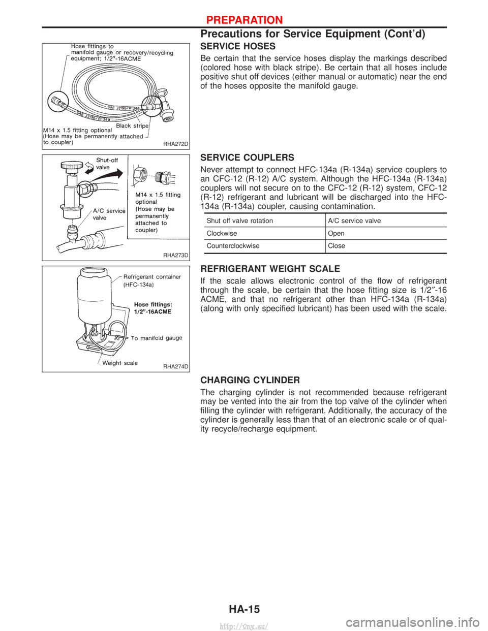
Be certain that the service hoses display the markings described
(colored hose with black stripe). Be certain that all hoses include
positive shut off devices (either manual or automatic) near the end
of the hoses opposite the manifold gauge.
SERVICE COUPLERS
Never attempt to connect HFC-134a (R-134a) service couplers to
an CFC-12 (R-12) A/C system. Although the HFC-134a (R-134a)
couplers will not secure on to the CFC-12 (R-12) system, CFC-12
(R-12) refrigerant and lubricant will be discharged into the HFC-
134a (R-134a) coupler, causing contamination.
Shut off valve rotationA/C service valve
Clockwise Open
Counterclockwise Close
REFRIGERANT WEIGHT SCALE
If the scale allows electronic control of the flow of refrigerant
through the scale, be certain that the hose fitting size is 1/2 ²-16
ACME, and that no refrigerant other than HFC-134a (R-134a)
(along with only specified lubricant) has been used with the scale.
CHARGING CYLINDER
The charging cylinder is not recommended because refrigerant
may be vented into the air from the top valve of the cylinder when
filling the cylinder with refrigerant. Additionally, the accuracy of the
cylinder is generally less than that of an electronic scale or of qual-
ity recycle/recharge equipment.
RHA272D
RHA273D
RHA274D
PREPARATION
Precautions for Service Equipment (Cont'd)
HA-15
http://vnx.su/
Page 1413 of 1833
HFC-134a (R-134a) Service Procedure
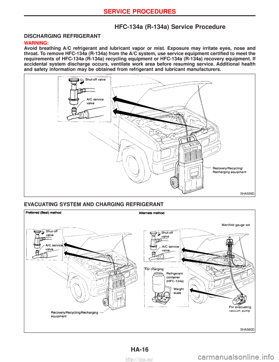
DISCHARGING REFRIGERANT
WARNING:
Avoid breathing A/C refrigerant and lubricant vapor or mist. Exposure may irritate eyes, nose and
throat. To remove HFC-134a (R-134a) from the A/C system, use service equipment certified to meet the
requirements of HFC-134a (R-134a) recycling equipment or HFC-134a (R-134a) recovery equipment. If
accidental system discharge occurs, ventilate work area before resuming service. Additional health
and safety information may be obtained from refrigerant and lubricant manufacturers.
EVACUATING SYSTEM AND CHARGING REFRIGERANT
SHA559D
SHA560D
SERVICE PROCEDURES
HA-16
http://vnx.su/
Page 1414 of 1833
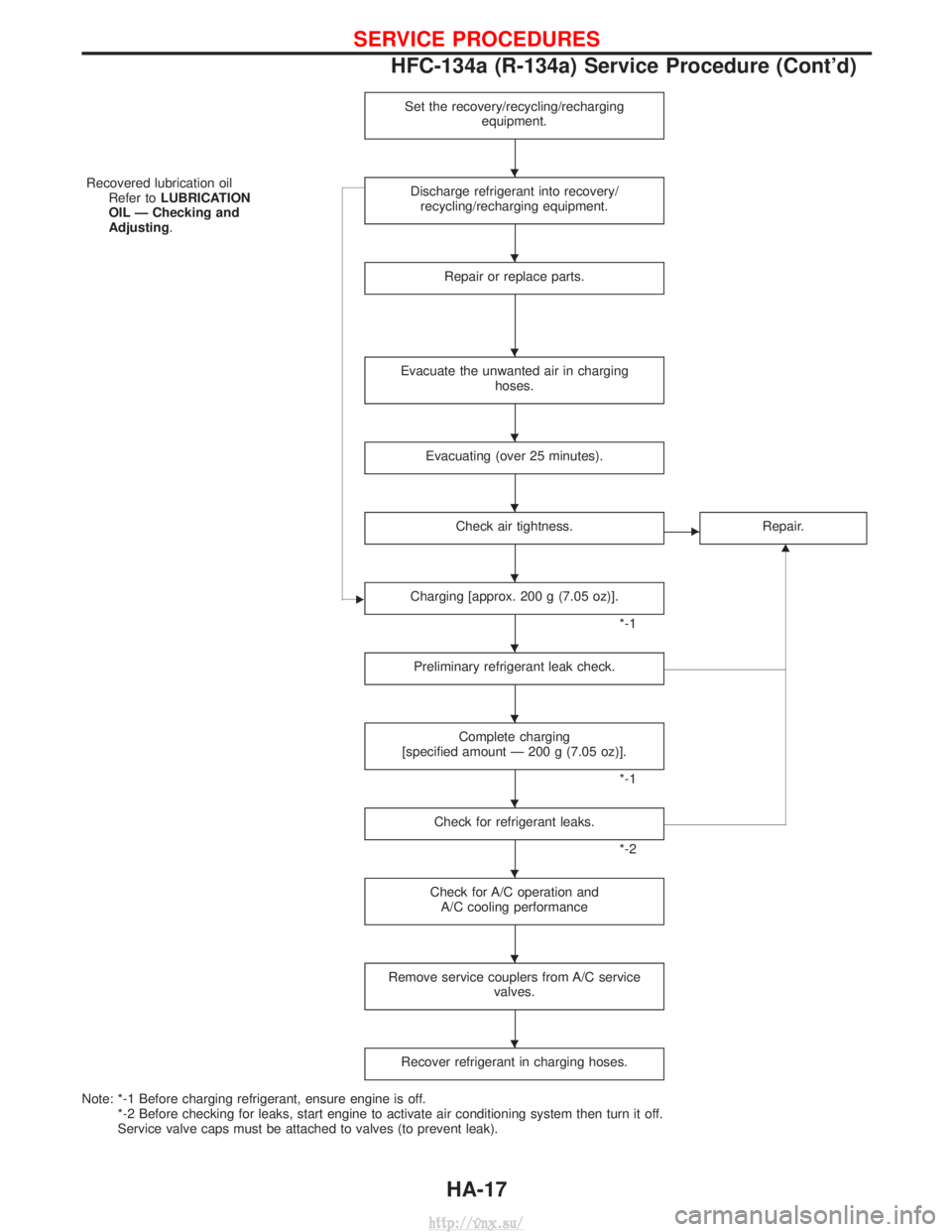
Set the recovery/recycling/rechargingequipment.
Recovered lubrication oilRefer to LUBRICATION
OIL Ð Checking and
Adjusting. Discharge refrigerant into recovery/
recycling/recharging equipment.
Repair or replace parts.
Evacuate the unwanted air in charging hoses.
Evacuating (over 25 minutes).
Check air tightness.ERepair.
G
ECharging [approx. 200 g (7.05 oz)].
*-1
Preliminary refrigerant leak check.
Complete charging
[specified amount Ð 200 g (7.05 oz)].
*-1
Check for refrigerant leaks.
*-2
Check for A/C operation and A/C cooling performance
Remove service couplers from A/C service valves.
Recover refrigerant in charging hoses.
Note: *-1 Before charging refrigerant, ensure engine is off.*-2 Before checking for leaks, start engine to activate air conditioning system then turn it off.
Service valve caps must be attached to valves (to prevent leak).
H
H
H
H
H
H
H
H
H
H
H
H
SERVICE PROCEDURES
HFC-134a (R-134a) Service Procedure (Cont'd)
HA-17
http://vnx.su/
Page 1415 of 1833
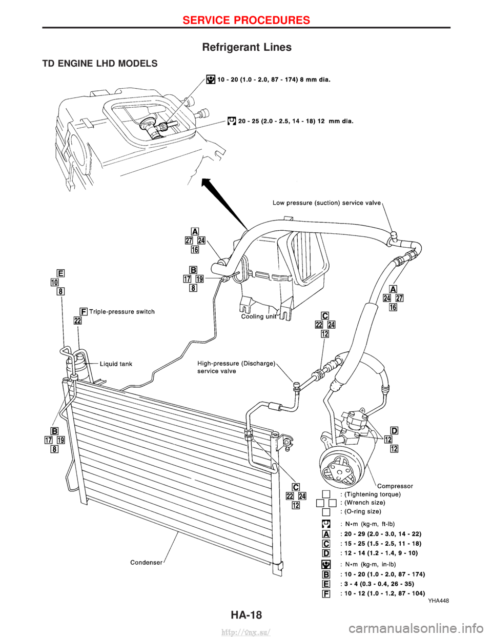
Refrigerant Lines
TD ENGINE LHD MODELS
YHA448
SERVICE PROCEDURES
HA-18
http://vnx.su/
Page 1416 of 1833

TD ENGINE RHD MODELS
YHA449
SERVICE PROCEDURES
Refrigerant Lines (Cont'd)HA-19
http://vnx.su/
Page 1417 of 1833
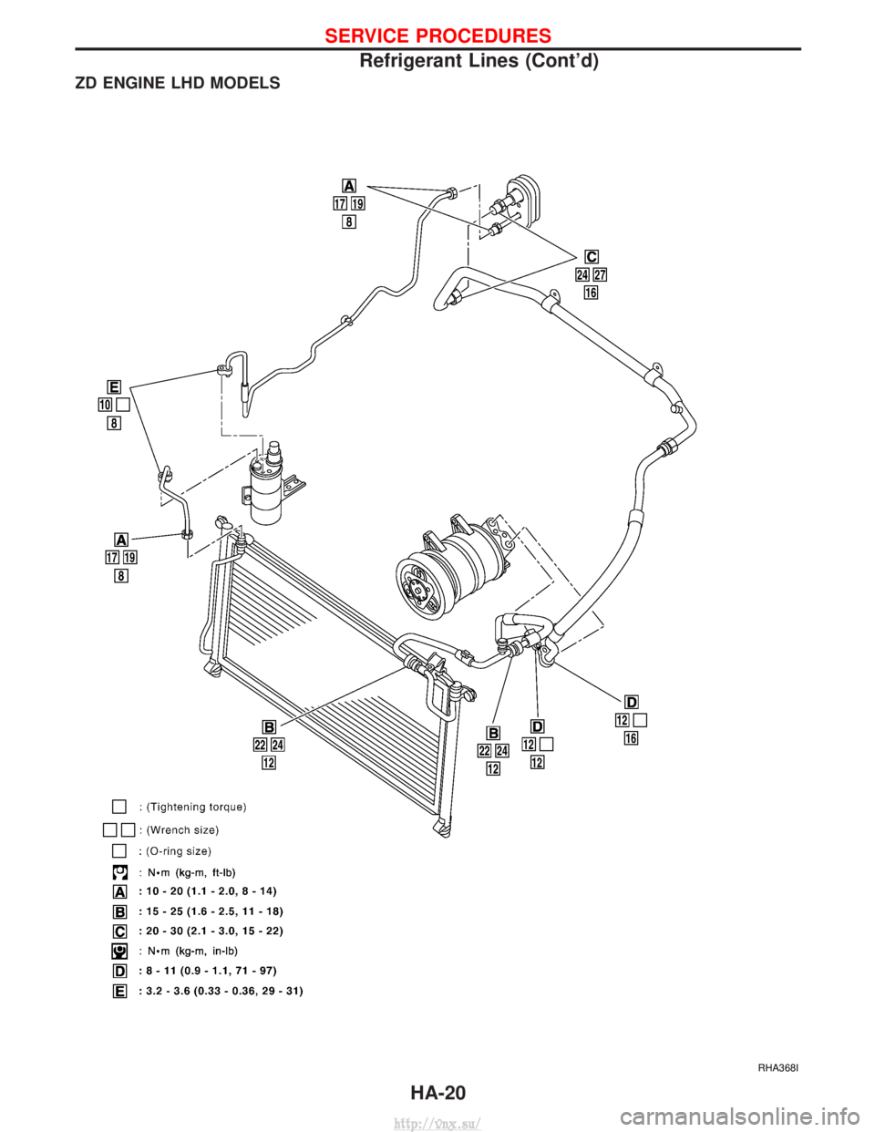
ZD ENGINE LHD MODELS
RHA368I
SERVICE PROCEDURES
Refrigerant Lines (Cont'd)HA-20
http://vnx.su/
Page 1418 of 1833
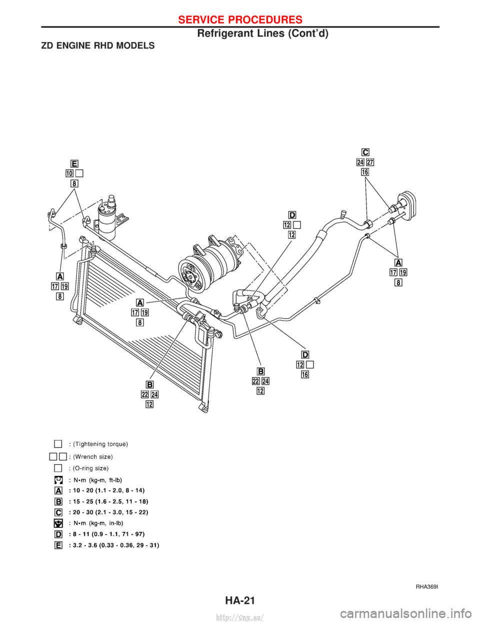
ZD ENGINE RHD MODELS
RHA369I
SERVICE PROCEDURES
Refrigerant Lines (Cont'd)HA-21
http://vnx.su/
Page 1419 of 1833
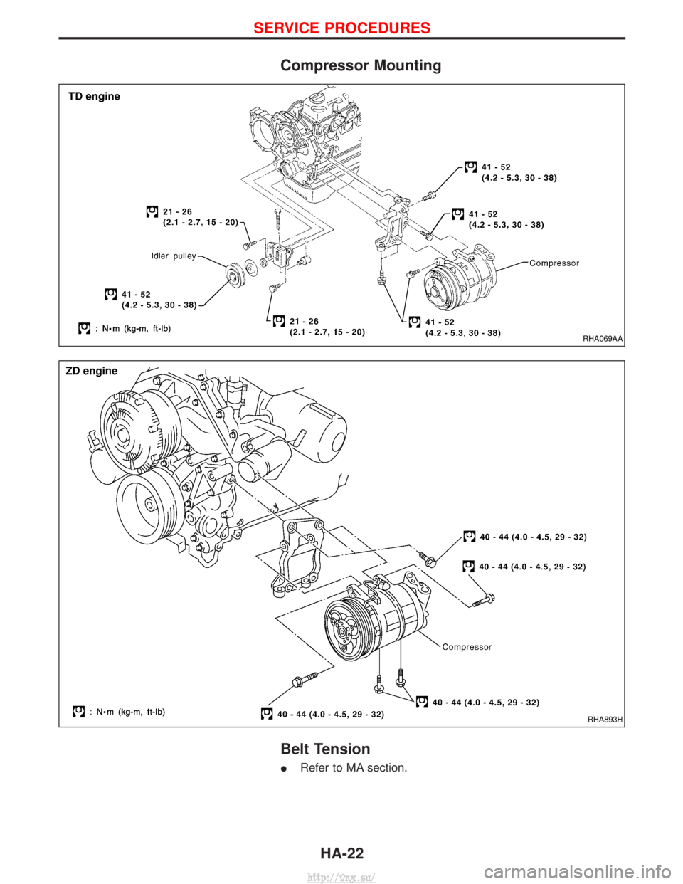
Compressor Mounting
Belt Tension
IRefer to MA section.
RHA069AA
RHA893H
SERVICE PROCEDURES
HA-22
http://vnx.su/
Page 1420 of 1833
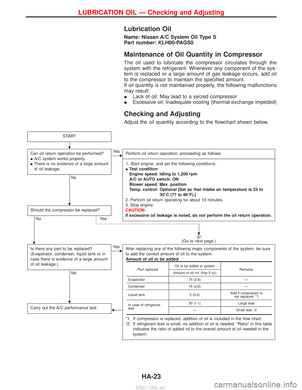
Lubrication Oil
Name: Nissan A/C System Oil Type S
Part number: KLH00-PAGS0
Maintenance of Oil Quantity in Compressor
The oil used to lubricate the compressor circulates through the
system with the refrigerant. Whenever any component of the sys-
tem is replaced or a large amount of gas leakage occurs, add oil
to the compressor to maintain the specified amount.
If oil quantity is not maintained properly, the following malfunctions
may result:
ILack of oil: May lead to a seized compressor
I Excessive oil: Inadequate cooling (thermal exchange impeded)
Checking and Adjusting
Adjust the oil quantity according to the flowchart shown below.
START
Can oil return operation be performed?
IA/C system works properly.
I There is no evidence of a large amount
of oil leakage.
No
EYe s
Perform oil return operation, proceeding as follows:
------------------------------------------------------------------------------------------------------------------------------------------------------------------------------------------------------------------------------------------------------------------------------------------------------------------------------------------------------------------------------------------------------------------------------------------------------------------------------------------------------------------------------------------------------------- 1. Start engine, and set the following conditions:
I Test condition
Engine speed: Idling to 1,200 rpm
A/C or AUTO switch: ON
Blower speed: Max. position
Temp. control: Optional [Set so that intake air temperature is 25 to
30ÉC (77 to 86ÉF).]
2. Perform oil return operating for about 10 minutes.
3. Stop engine.
CAUTION:
If excessive oil leakage is noted, do not perform the oil return operation.
Should the compressor be replaced?
No Yes
qA(Go to next page.)
Is there any part to be replaced?
(Evaporator, condenser, liquid tank or in
case there is evidence of a large amount
of oil leakage.)
No
EYe s After replacing any of the following major components of the system, be sure
to add the correct amount of oil to the system.
Amount of oil to be added
*1: If compressor is replaced, addition of oil is included in the flow chart.
*2: If refrigerant leak is small, no addition of oil is needed. ªRatioº in this table indicates the ratio of added oil to the overall amount of oil needed in the
system.
Carry out the A/C performance test.F
Part replaced Oil to be added to system
Remarks
Amount of oil m (Imp fl oz)
Evaporator 75 (2.6)Ð
Condenser 75 (2.6)Ð
Liquid tank 5 (0.2)Add if compressor is
not replaced. *1
In case of refrigerant
leak 30 (1.1)
Large leak
Ð Small leak *2
H
H
H
H
H
LUBRICATION OIL Ð Checking and Adjusting
HA-23
http://vnx.su/